——
#DonLucElectronics #DonLuc #EEPROM #HMC5883L #Compass #ADXL345 #Accelerometer #Movement #ESP32 #Bluetooth #Elecrow #DFRobot #Arduino #Project #Patreon #Electronics #Microcontrollers #IoT #Fritzing #Programming #Consultant
——
——
——
——
EEPROM
EEPROM (Electrically Erasable Programmable Read-only Memory) is a type of non-volatile memory. EEPROM is a type of non-volatile ROM that enables individual bytes of data to be erased and reprogrammed. That is why EEPROM chips are known as byte erasable chips. EEPROM is usually used to store small amounts of data in computing and other electronic devices. It is used in computers, usually integrated in microcontrollers such as smart cards and remote keyless systems, or as a separate chip device, to store relatively small amounts of data by allowing individual bytes to be erased and reprogrammed.
The microcontroller on the Arduino boards have 512 bytes of EEPROM: memory whose values are kept when the board is turned off. Functions in the EEPROM class are automatically included with the platform for your board, meaning you do not need to install any external libraries. The supported microcontrollers on the various Arduino have different amounts of EEPROM: 1024 bytes on the ATmega328P, 512 bytes on the ATmega168 and ATmega8, 4 KB (4096 bytes) on the ATmega1280 and ATmega2560. The Arduino boards have an emulated EEPROM space of 1024 bytes. The EEPROM library on ESP32 provides a reliable way to store data persistently, so that it remains accessible even when the power supply is disconnected. Unlike RAM, the data we save with the EEPROM library does not get lost when power is cut. This feature makes it an ideal choice for retaining configurations, settings, and other important data in embedded devices like the ESP32.
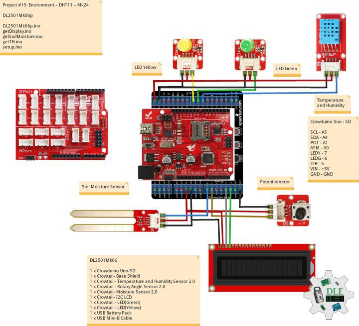
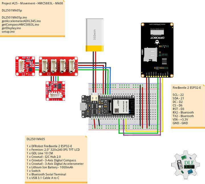
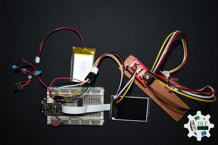
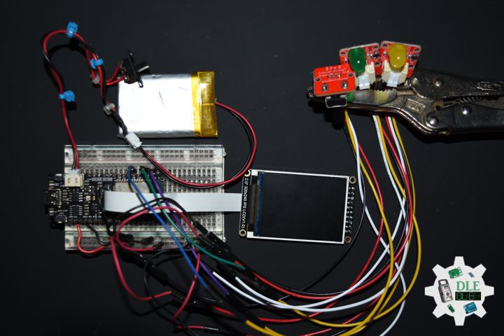
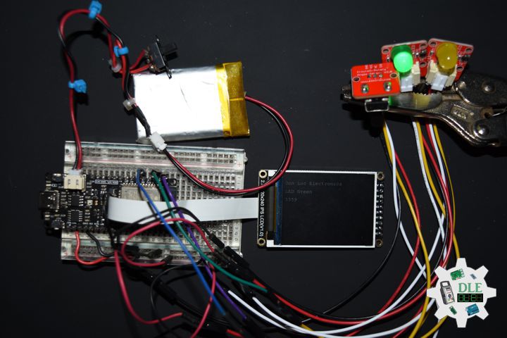
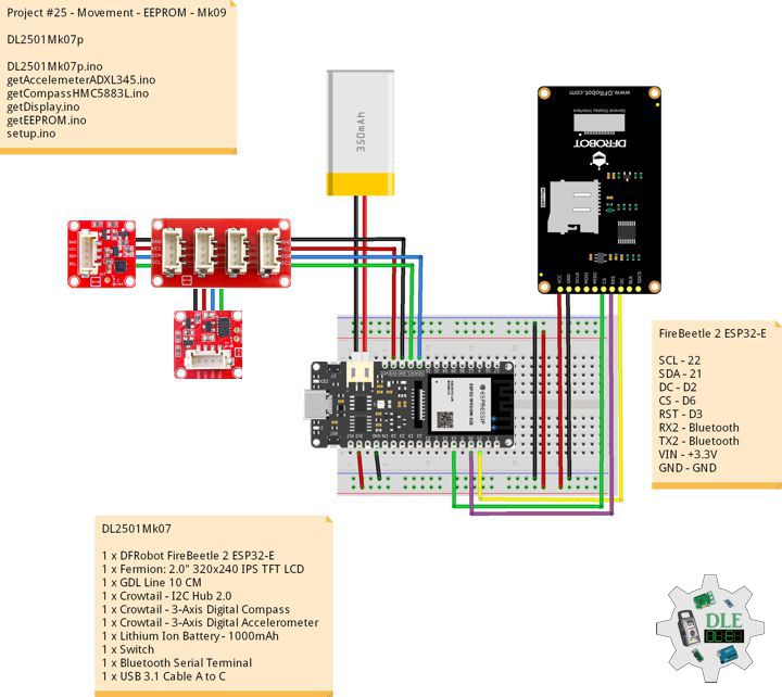
DL2501Mk07
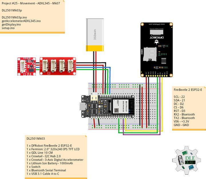
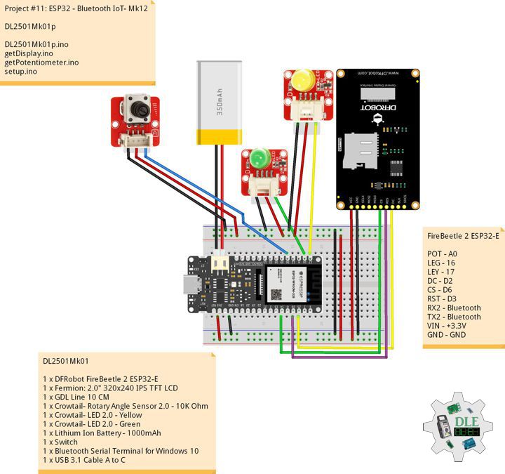
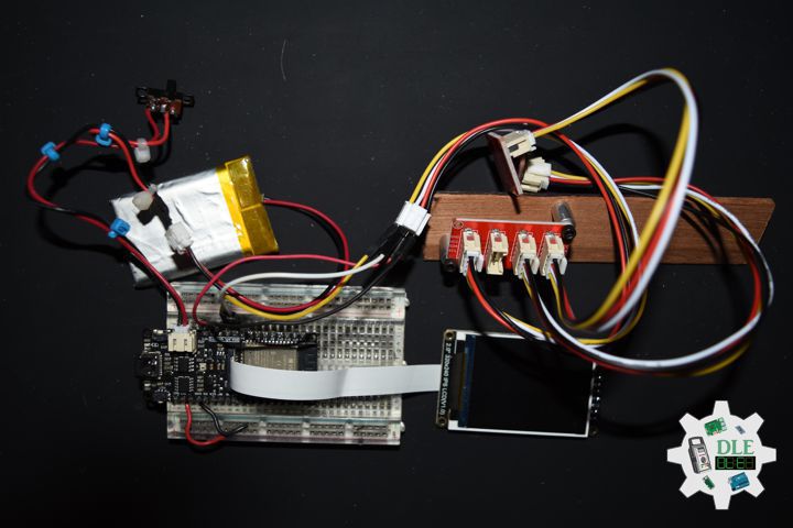
1 x DFRobot FireBeetle 2 ESP32-E
1 x Fermion: 2.0″ 320×240 IPS TFT LCD
1 x GDL Line 10 CM
1 x Crowtail – I2C Hub 2.0
1 x Crowtail – 3-Axis Digital Compass
1 x Crowtail – 3-Axis Digital Accelerometer
1 x Lithium Ion Battery – 1000mAh
1 x Switch
1 x Bluetooth Serial Terminal
1 x USB 3.1 Cable A to C
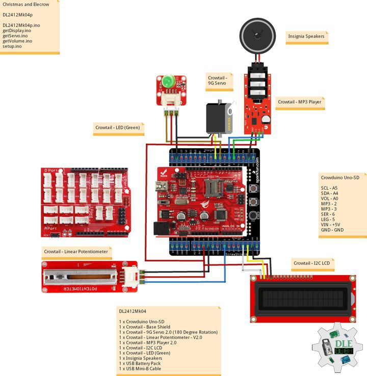
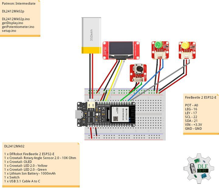
FireBeetle 2 ESP32-E
SCL – 22
SDA – 21
DC – D2
CS – D6
RST – D3
RX2 – Bluetooth
TX2 – Bluetooth
VIN – +3.3V
GND – GND
DLE-EEPROM-UID-ESP32Mk001
DLE-EEPROM-UID-ESP32Mk001.ino
/* ***** Don Luc Electronics © ******
Software Version Information
DLE-EEPROM-UID-ESP32Mk001
ver: ESPMk001
EEPROM with unique ID
*/

// Include Library Code
// EEPROM library to read and write EEPROM with unique ID for unit
#include "EEPROM.h"

// The current address in the EEPROM (i.e. which byte
// we're going to write to next)
#define EEPROM_SIZE 64

// Software Version Information
String sver = "ESPMk001";
// Unit ID information
String uid = "DLE0001";
// Read Unique ID
// String ruid = "";

void loop()
{

   // <== Write and Read EEPROM
   isEEPROMw();

}
getEEPROM.ino
// getEEPROM
// Write and Read EEPROM with Unique ID for Unit
void isEEPROMw() {

  // EEPROM
  int incb = 0;
  int v = 0;
  String msg = "";
  String emp = "";
  String ruid = "";

  // Set Unit ID
  // The message starts with sid then is followed by 5 characters
  // First clear a string buffer
  emp = "";
  // Loop through the 7 ID characters and write their ASCII (byte) value to the EEPROM
  for (int x = 0; x < 7; x++)
    {
       // Get ASCII value of character
       v = int(uid.charAt(x)); // + 5));
       // Add the actual character to the buffer so we can send it back to the PC
       emp = emp + uid.charAt(x + 5);
       // Write the value to the EEPROM
       EEPROM.write(x, v);
       EEPROM.commit();
    }

   delay( 500 );

   // Write EEPROM with Unique ID for Unit
   Serial.println( "Write ID Information");

  // Read ID Information
  // Unit ID
  for (int y = 0; y < 7; y++)
  {

    ruid = ruid + char(EEPROM.read(y));

  }

  // Read ID Information
  Serial.print( "Read ID Information: ");
  Serial.println( ruid );
  Serial.println( "Ok!" );
  ruid = "";

  delay( 5000 );

}
setup.ino
// Setup
void setup()
{

  // EEPROM with unique ID
  EEPROM.begin(EEPROM_SIZE);

  // Open the serial port at 9600 bps:
  Serial.begin(9600);

  // Serial
  Serial.print( "Software Version Information: ");
  Serial.println( sver );
  Serial.print( "Unit ID Information: ");
  Serial.println( uid );

  delay(5000);

}
——
DL2501Mk07p
DL2501Mk07p.ino
/****** Don Luc Electronics © ******
Software Version Information
Project #25 - Movement - EEPROM - Mk09
25-09
DL2501Mk07p.ino
DL2501Mk07
1 x DFRobot FireBeetle 2 ESP32-E
1 x Fermion: 2.0" 320x240 IPS TFT LCD
1 x GDL Line 10 CM
1 x Crowtail - I2C Hub 2.0
1 x Crowtail - 3-Axis Digital Compass
1 x Crowtail - 3-Axis Digital Accelerometer
1 x Lithium Ion Battery - 1000mAh
1 x Switch
1 x Bluetooth Serial Terminal
1 x USB 3.1 Cable A to C
*/

// Include the Library Code
// EEPROM Library to Read and Write EEPROM
// with Unique ID for Unit
#include "EEPROM.h"
// Arduino
#include <Arduino.h>
// Wire
#include <Wire.h>
// DFRobot Display GDL API
#include <DFRobot_GDL.h>
// Bluetooth Serial
#include "BluetoothSerial.h"
#if !defined(CONFIG_BT_ENABLED) || !defined(CONFIG_BLUEDROID_ENABLED)
#error Bluetooth is not enabled! Please run `make menuconfig` to and enable it
#endif
// Accelemeter ADXL345
#include <ADXL345.h>
// Compass HMC5883L
#include <HMC5883L.h>

// Compass HMC5883L
HMC5883L compass;
// Heading
float heading;
// Heading Degrees
float headingDegrees;

// Variable ADXL345 library
ADXL345 adxl;
// Accelerometer ADXL345
// x, y, z
int x;
int y;
int z;
// Standard Gravity
// xyz
double xyz[3];
double ax;
double ay;
double az;

// FullString
String FullString = "";

// Bluetooth Serial
BluetoothSerial SerialBT;

// Defined ESP32
#define TFT_DC  D2
#define TFT_CS  D6
#define TFT_RST D3

/*dc=*/ /*cs=*/ /*rst=*/
// DFRobot Display 240x320
DFRobot_ST7789_240x320_HW_SPI screen(TFT_DC, TFT_CS, TFT_RST);

// EEPROM Unique ID Information
#define EEPROM_SIZE 64
String uid = "";

// Software Version Information
String sver = "25-09";

void loop() {

  // Accelemeter ADXL345
  isADXL345();

  // Compass HMC5883L
  isHMC5883L();

  // isEEPROM
  isEEPROM();

  // Accelemeter ADXL345 Compass HMC5883L Display
  isDisplayADXL345HMC5883L();

  // Delay 0.5 Second
  delay( 500 );

}
getAccelemeterADXL345.ino
// Accelemeter ADXL345
// Setup Accelemeter ADXL345
void isSetupADXL345(){

  // Power On
  adxl.powerOn();

  // Set activity inactivity thresholds (0-255)
  // 62.5mg per increment
  adxl.setActivityThreshold(75);
  // 62.5mg per increment
  adxl.setInactivityThreshold(75);
  // How many seconds of no activity is inactive?
  adxl.setTimeInactivity(10);

  //look of activity movement on this axes - 1 == on; 0 == off
  adxl.setActivityX(1);
  adxl.setActivityY(1);
  adxl.setActivityZ(1);

  //look of inactivity movement on this axes - 1 == on; 0 == off
  adxl.setInactivityX(1);
  adxl.setInactivityY(1);
  adxl.setInactivityZ(1);

  // Look of tap movement on this axes - 1 == on; 0 == off
  adxl.setTapDetectionOnX(0);
  adxl.setTapDetectionOnY(0);
  adxl.setTapDetectionOnZ(1);

  // Set values for what is a tap, and what is a double tap (0-255)
  // 62.5mg per increment
  adxl.setTapThreshold(50);
  // 625us per increment
  adxl.setTapDuration(15);
  // 1.25ms per increment
  adxl.setDoubleTapLatency(80);
  // 1.25ms per increment
  adxl.setDoubleTapWindow(200);

  // set values for what is considered freefall (0-255)
  // (5 - 9) recommended - 62.5mg per increment
  adxl.setFreeFallThreshold(7);
  // (20 - 70) recommended - 5ms per increment
  adxl.setFreeFallDuration(45);

  // Setting all interrupts to take place on int pin 1
  // I had issues with int pin 2, was unable to reset it
  adxl.setInterruptMapping( ADXL345_INT_SINGLE_TAP_BIT,   ADXL345_INT1_PIN );
  adxl.setInterruptMapping( ADXL345_INT_DOUBLE_TAP_BIT,   ADXL345_INT1_PIN );
  adxl.setInterruptMapping( ADXL345_INT_FREE_FALL_BIT,    ADXL345_INT1_PIN );
  adxl.setInterruptMapping( ADXL345_INT_ACTIVITY_BIT,     ADXL345_INT1_PIN );
  adxl.setInterruptMapping( ADXL345_INT_INACTIVITY_BIT,   ADXL345_INT1_PIN );

  // Register interrupt actions - 1 == on; 0 == off
  adxl.setInterrupt( ADXL345_INT_SINGLE_TAP_BIT, 1);
  adxl.setInterrupt( ADXL345_INT_DOUBLE_TAP_BIT, 1);
  adxl.setInterrupt( ADXL345_INT_FREE_FALL_BIT,  1);
  adxl.setInterrupt( ADXL345_INT_ACTIVITY_BIT,   1);
  adxl.setInterrupt( ADXL345_INT_INACTIVITY_BIT, 1);

}
// Accelemeter ADXL345
void isADXL345(){

  // Read the accelerometer values and store them in variables  x,y,z
  adxl.readXYZ(&x, &y, &z);

  // Output
  // FullString
  // ************
  FullString = "************\r\n";
  // FullString Bluetooth Serial + Serial
  for(int i = 0; i < FullString.length(); i++)
  {

    // Bluetooth Serial
    SerialBT.write(FullString.c_str()[i]);
    // Serial
    Serial.write(FullString.c_str()[i]);

  }

  // FullString
  FullString = "Values of X , Y , Z: " + String(x) + " , " +
  String(y) + " , " + String(z) + + "\r\n";

  // FullString Bluetooth Serial + Serial
  for(int i = 0; i < FullString.length(); i++)
  {

    // Bluetooth Serial
    SerialBT.write(FullString.c_str()[i]);
    // Serial
    Serial.write(FullString.c_str()[i]);

  }

  // Standard Gravity
  // Acceleration
  adxl.getAcceleration(xyz);

  // Output
  ax = xyz[0];
  ay = xyz[1];
  az = xyz[2];

  // FullString
  // ************
  FullString = "************\r\n";
  // FullString Bluetooth Serial + Serial
  for(int i = 0; i < FullString.length(); i++)
  {

    // Bluetooth Serial
    SerialBT.write(FullString.c_str()[i]);
    // Serial
    Serial.write(FullString.c_str()[i]);

  }

  // FullString
  // xg
  FullString = "X = " + String(ax) + " g" + "\r\n";
  // FullString Bluetooth Serial + Serial
  for(int i = 0; i < FullString.length(); i++)
  {

    // Bluetooth Serial
    SerialBT.write(FullString.c_str()[i]);
    // Serial
    Serial.write(FullString.c_str()[i]);

  }
  // yg
  FullString = "y = " + String(ay) + " g" + "\r\n";
  // FullString Bluetooth Serial + Serial
  for(int i = 0; i < FullString.length(); i++)
  {

    // Bluetooth Serial
    SerialBT.write(FullString.c_str()[i]);
    // Serial
    Serial.write(FullString.c_str()[i]);

  }
  // zg
  FullString = "z = " + String(az) + " g" + "\r\n";
  // FullString Bluetooth Serial + Serial
  for(int i = 0; i < FullString.length(); i++)
  {

    // Bluetooth Serial
    SerialBT.write(FullString.c_str()[i]);
    // Serial
    Serial.write(FullString.c_str()[i]);

  }

}
getCompassHMC5883L.ino
// HMC5883L Triple Axis Digital Compass
// Setup HMC5883L
void isSetupHMC5883L(){

  // Initialize Initialize HMC5883L
  compass.begin();

  // Set measurement range
  compass.setRange(HMC5883L_RANGE_1_3GA);

  // Set measurement mode
  compass.setMeasurementMode(HMC5883L_CONTINOUS);

  // Set data rate
  compass.setDataRate(HMC5883L_DATARATE_30HZ);

  // Set number of samples averaged
  compass.setSamples(HMC5883L_SAMPLES_8);

  // Set calibration offset
  compass.setOffset(0, 0);

}
// Compass HMC5883L
void isHMC5883L(){

  // Vector norm
  Vector norm = compass.readNormalize();

  // Calculate heading
  heading = atan2(norm.YAxis, norm.XAxis);

  // Set declination angle on your location and fix heading
  // You can find your declination on: http://magnetic-declination.com/
  // (+) Positive or (-) for negative
  // Latitude: 32° 39' 7.9" N
  // Longitude: 115° 28' 6.2" W
  // Magnetic Declination: +10° 35'
  // Declination is POSITIVE (EAST)
  // Inclination: 58° 4'
  // Magnetic field strength: 45759.1 nT
  // Formula: (deg + (min / 60.0)) / (180 / M_PI);
  float declinationAngle = (10.0 + (35.0 / 60.0)) / (180 / M_PI);
  heading += declinationAngle;

  // Correct for heading < 0deg and heading > 360deg
  if (heading < 0)
  {
    heading += 2 * PI;
  }

  if (heading > 2 * PI)
  {
    heading -= 2 * PI;
  }

  // Convert to degrees
  headingDegrees = heading * 180/M_PI;

  // Output
  // FullString
  // ************
  FullString = "************\r\n";
  // FullString Bluetooth Serial + Serial
  for(int i = 0; i < FullString.length(); i++)
  {

    // Bluetooth Serial
    SerialBT.write(FullString.c_str()[i]);
    // Serial
    Serial.write(FullString.c_str()[i]);

  }

  // FullString
  // Heading
  FullString = "Heading = " + String( heading ) + "\r\n";
  // FullString Bluetooth Serial + Serial
  for(int i = 0; i < FullString.length(); i++)
  {

    // Bluetooth Serial
    SerialBT.write(FullString.c_str()[i]);
    // Serial
    Serial.write(FullString.c_str()[i]);

  }

  // FullString
  // Degress
  FullString = "Degress = " + String( headingDegrees ) + "\r\n";
  // FullString Bluetooth Serial + Serial
  for(int i = 0; i < FullString.length(); i++)
  {

    // Bluetooth Serial
    SerialBT.write(FullString.c_str()[i]);
    // Serial
    Serial.write(FullString.c_str()[i]);

  }

}
getDisplay.ino
// DFRobot Display 240x320
// DFRobot Display 240x320 - UID
void isDisplayUID(){
// DFRobot Display 240x320
// Text Display
// Text Wrap
screen.setTextWrap(false);
// Rotation
screen.setRotation(3);
// Fill Screen => black
screen.fillScreen(0x0000);
// Text Color => white
screen.setTextColor(0xffff);
// Font => Free Sans Bold 12pt
screen.setFont(&FreeSansBold12pt7b);
// TextSize => 1.5
screen.setTextSize(1.5);
// Don Luc Electronics
screen.setCursor(0, 30);
screen.println("Don Luc Electronics");
// EEPROM
screen.setCursor(0, 60);
screen.println("EEPROM");
// Version
screen.setCursor(0, 90);
screen.println("Version");
screen.setCursor(0, 120);
screen.println( sver );
// EEPROM
screen.setCursor(0, 150);
screen.println("EEPROM");
screen.setCursor(0, 180);
screen.println( uid );
}
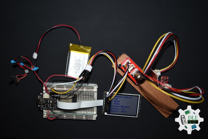
// Accelemeter ADXL345
void isDisplayADXL345HMC5883L(){
// DFRobot Display 240x320
// Text Display
// Text Wrap
screen.setTextWrap(false);
// Rotation
screen.setRotation(3);
// Fill Screen => white
screen.fillScreen(0xffff);
// Text Color => blue
screen.setTextColor(0x001F);
// Font => Free Sans Bold 12pt
screen.setFont(&FreeSansBold12pt7b);
// TextSize => 1.5
screen.setTextSize(1.5);
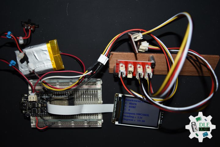
// Accelemeter ADXL345
screen.setCursor(0, 30);
screen.println("Accelemeter ADXL345");
// Accelemeter ADXL345 X
screen.setCursor(0, 60);
screen.println("X: ");
screen.setCursor(40, 60);
screen.println( x );
// Accelemeter ADXL345 Y
screen.setCursor(0, 90);
screen.println( "Y: " );
screen.setCursor(40, 90);
screen.println( y );
// Accelemeter ADXL345 Z
screen.setCursor(0, 120);
screen.println( "Z: " );
screen.setCursor(40, 120);
screen.println( z );
// Compass HMC5883L
screen.setCursor(0, 150);
screen.println( "Compass HMC5883L" );
// Heading
screen.setCursor(0, 180);
screen.println( "Heading = " );
screen.setCursor(130, 180);
screen.println( heading );
// Degress
screen.setCursor(0, 210);
screen.println( "Degress = " );
screen.setCursor(130, 210);
screen.println( headingDegrees );
}
getEEPROM.ino
// EEPROM
// isUID EEPROM Unique ID
void isUID() {

  // Is Unit ID
  uid = "";
  for (int x = 0; x < 7; x++)
  {
    uid = uid + char(EEPROM.read(x));
  }

}
// isEEPROM
void isEEPROM(){

  // FullString
  // ************
  FullString = "************\r\n";
  // FullString Bluetooth Serial + Serial
  for(int i = 0; i < FullString.length(); i++)
  {

    // Bluetooth Serial
    SerialBT.write(FullString.c_str()[i]);
    // Serial
    Serial.write(FullString.c_str()[i]);

  }

  // FullString
  // EEPROM
  FullString = "EEPROM = " + String( uid ) + "\r\n";
  // FullString Bluetooth Serial + Serial
  for(int i = 0; i < FullString.length(); i++)
  {

    // Bluetooth Serial
    SerialBT.write(FullString.c_str()[i]);
    // Serial
    Serial.write(FullString.c_str()[i]);

  }

}
setup.ino
// Setup
void setup()
{

  // Serial Begin
  Serial.begin(115200);
  Serial.println("Starting BLE work!");

  // Bluetooth Serial
  SerialBT.begin("DL2501Mk07");
  Serial.println("Bluetooth Started! Ready to pair...");

  // Delay
  delay( 100 );

  // EEPROM Size
  EEPROM.begin(EEPROM_SIZE);

  // EEPROM Unique ID
  isUID();

  // Delay
  delay(100);

  // DFRobot Display 240x320
  screen.begin();

  // Delay
  delay(100);

  // Setup Accelemeter ADXL345
  isSetupADXL345();

  // Setup HMC5883L
  isSetupHMC5883L();

  // DFRobot Display 240x320 - UID
  // Don Luc Electronics
  // Version
  isDisplayUID();

  // Delay 5 Second
  delay( 5000 );

}
——
People can contact us: https://www.donluc.com/?page_id=1927
Electronics, IoT, Teacher, Instructor, R&D and Consultant
- Programming Language
- Single-Board Microcontrollers (PIC, Arduino, Raspberry Pi, Arm, Silicon Labs, Espressif, Etc…)
- IoT
- Wireless (Radio Frequency, Bluetooth, WiFi, Etc…)
- Robotics
- Automation
- Camera and Video Capture Receiver Stationary, Wheel/Tank and Underwater Vehicle
- Unmanned Vehicles Terrestrial and Marine
- Machine Learning
- Artificial Intelligence (AI)
- RTOS
- Sensors, eHealth Sensors, Biosensor, and Biometric
- Research & Development (R & D)
- Consulting
Follow Us
Luc Paquin – Curriculum Vitae – 2025
https://www.donluc.com/luc/
Web: https://www.donluc.com/
Facebook: https://www.facebook.com/neosteam.labs.9/
YouTube: https://www.youtube.com/@thesass2063
Twitter: https://twitter.com/labs_steam
Pinterest: https://www.pinterest.com/NeoSteamLabs/
Instagram: https://www.instagram.com/neosteamlabs/
Patreon: https://patreon.com/DonLucElectronics59
DFRobot: https://learn.dfrobot.com/user-10186.html
Hackster.io: https://www.hackster.io/neosteam-labs
Elecrow: https://www.elecrow.com/share/sharepj/center/no/760816d385ebb1edc0732fd873bfbf13
TikTok: https://www.tiktok.com/@luc.paquin8
Twitch: https://www.twitch.tv/lucpaquin
LinkedIn: https://www.linkedin.com/in/jlucpaquin/
Don Luc