——
#DonLucElectronics #DonLuc #SD #GPS #RTC #EEPROM #Compass #Accelerometer #Movement #ESP32 #Bluetooth #Elecrow #DFRobot #Arduino #Project #Patreon #Electronics #Microcontrollers #IoT #Fritzing #Programming #Consultant
——
——
——
——
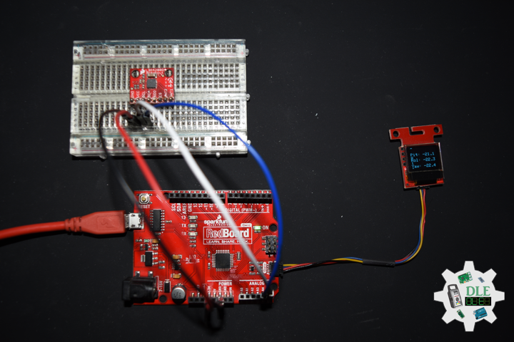
MicroSD Card Module
There are different microSD card modules compatible with the ESP32. We’re using the microSD card module it communicates using SPI communication protocol. You can use any other microSD card module with an SPI interface. This microSD card module is also compatible with other microcontrollers like the Arduino boards. To learn how to use the microSD card module with the Arduino. You can connect it to the ESP32 using the default SPI pins.
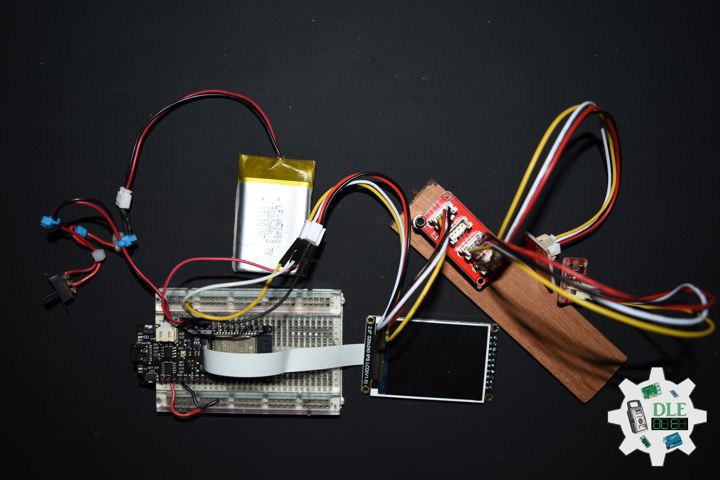
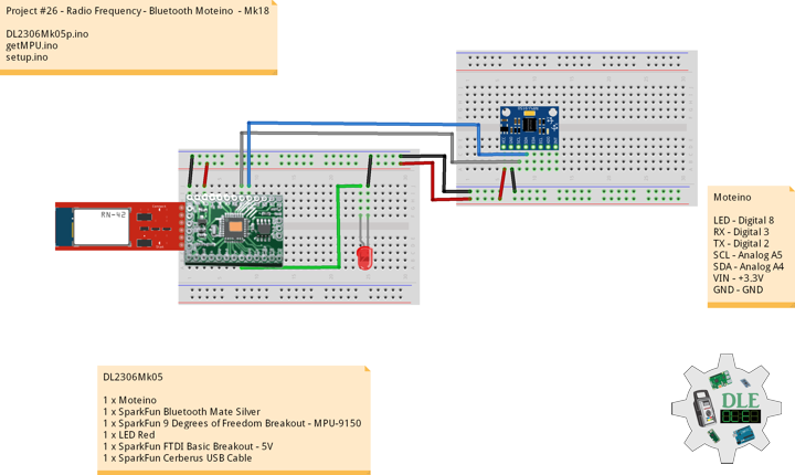
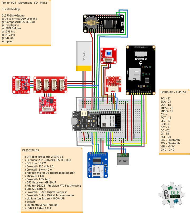
DL2502Mk05
1 x DFRobot FireBeetle 2 ESP32-E
1 x Fermion: 2.0″ 320×240 IPS TFT LCD
1 x GDL Line 10 CM
1 x Crowtail – I2C Hub 2.0
1 x Crowtail – Switch 2.0
1 x Adafruit MicroSD card breakout board+
1 x MicroSD 4 GB
1 x Crowtail – LED(Red)
1 x GPS Receiver – GP-20U7
1 x Adafruit DS3231 Precision RTC FeatherWing
1 x CR1220 Battery
1 x Crowtail – 3-Axis Digital Compass
1 x Crowtail – 3-Axis Digital Accelerometer
1 x Lithium Ion Battery – 1000mAh
1 x Switch
1 x Bluetooth Serial Terminal
1 x USB 3.1 Cable A to C
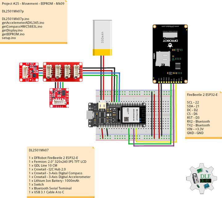
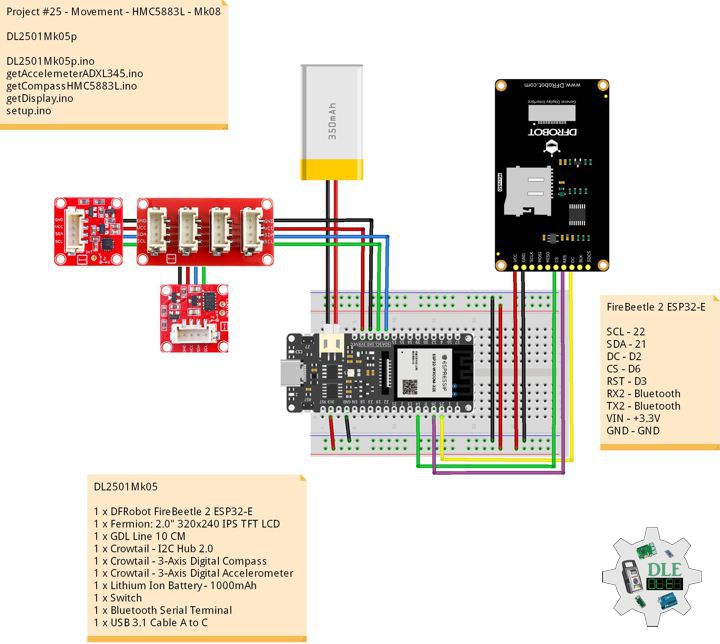
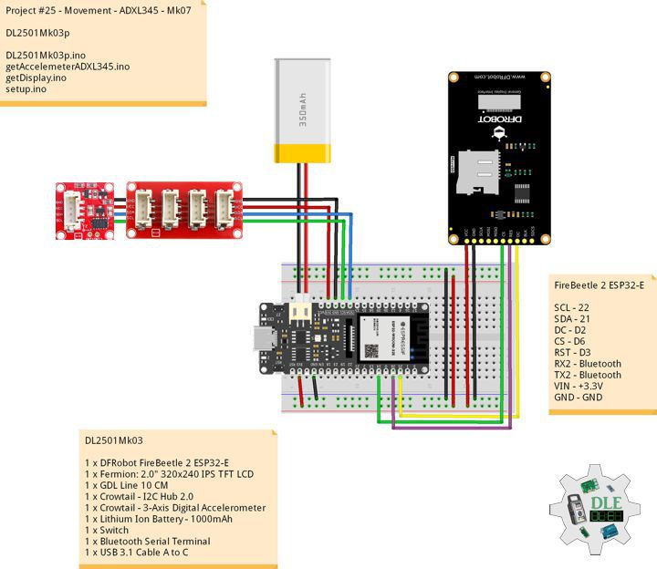
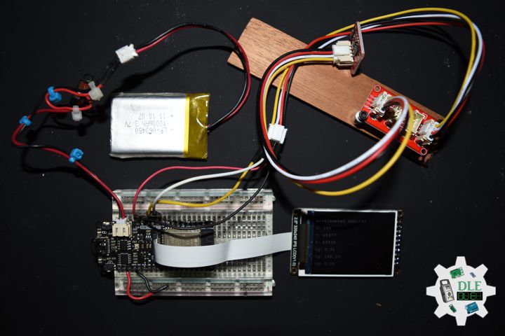
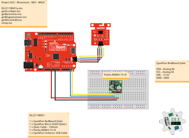
FireBeetle 2 ESP32-E
SCL – 22
SDA – 21
SCK – 18
MOSI – 23
MISO – 19
CS – 4
POT – 16
LED – 17
GPR – 0
GPT – 2
DC – D2
CS – D6
RST – D3
RX2 – Bluetooth
TX2 – Bluetooth
VIN – +3.3V
GND – GND
DL2502Mk05p
DL2502Mk05p.ino
/****** Don Luc Electronics © ******
  Software Version Information
  Project #25 - Movement - SD - Mk12
  25-12
  DL2502Mk05p.ino
  DL2502Mk05
  1 x DFRobot FireBeetle 2 ESP32-E
  1 x Fermion: 2.0" 320x240 IPS TFT LCD
  1 x GDL Line 10 CM
  1 x Crowtail - I2C Hub 2.0
  1 x Crowtail - Switch 2.0
  1 x Adafruit MicroSD card breakout board+
  1 x MicroSD 4 GB
  1 x Crowtail - LED(Red)
  1 x GPS Receiver - GP-20U7
  1 x Adafruit DS3231 Precision RTC FeatherWing
  1 x CR1220 Battery
  1 x Crowtail - 3-Axis Digital Compass
  1 x Crowtail - 3-Axis Digital Accelerometer
  1 x Lithium Ion Battery - 1000mAh
  1 x Switch
  1 x Bluetooth Serial Terminal
  1 x USB 3.1 Cable A to C
*/

// Include the Library Code
// EEPROM Library to Read and Write EEPROM
// with Unique ID for Unit
#include "EEPROM.h"
// Arduino
#include <Arduino.h>
// Wire
#include <Wire.h>
// DFRobot Display GDL API
#include <DFRobot_GDL.h>
// Bluetooth Serial
#include "BluetoothSerial.h"
#if !defined(CONFIG_BT_ENABLED) || !defined(CONFIG_BLUEDROID_ENABLED)
#error Bluetooth is not enabled! Please run `make menuconfig` to and enable it
#endif
// Accelemeter ADXL345
#include <ADXL345.h>
// Compass HMC5883L
#include <HMC5883L.h>
// RTC (Real-Time Clock)
#include "RTClib.h"
// GPS Receiver
#include <TinyGPS++.h>
// ESP32 Hardware Serial
#include <HardwareSerial.h>
// SD Card
#include "FS.h"
#include "SD.h"
#include "SPI.h"

// Define LED Red
int iLED = 17;

// Switch
int iSwitch = 16;
// Variable for reading the Switch status
int iSwitchState = 0;

// MicroSD Card
const int chipSelect = 4;
String zzzzzz = "";

// ESP32 HardwareSerial
HardwareSerial tGPS(1);

// GPS Receiver
#define gpsRXPIN 0
// This one is unused and doesnt have a conection
#define gpsTXPIN 2
// The TinyGPS++ object
TinyGPSPlus gps;
// Latitude
float TargetLat;
// Longitude
float TargetLon;
// GPS Date, Time, Speed, Altitude
// GPS Date
String TargetDat;
// GPS Time
String TargetTim;
// GPS Speeds M/S
String TargetSMS;
// GPS Speeds Km/h
String TargetSKH;
// GPS Altitude Meters
String TargetALTM;
// GPS Altitude Feet
String TargetALTF;
// GPS Status
String GPSSt = "";

// RTC (Real-Time Clock)
RTC_DS3231 rtc;
String dateRTC = "";
String timeRTC = "";
String tempRTC = "";

// Compass HMC5883L
HMC5883L compass;
// Heading
float heading;
// Heading Degrees
float headingDegrees;

// Variable ADXL345 library
ADXL345 adxl;
// Accelerometer ADXL345
// x, y, z
int x;
int y;
int z;
// Standard Gravity
// xyz
double xyz[3];
double ax;
double ay;
double az;

// FullString
String FullString = "";

// Bluetooth Serial
BluetoothSerial SerialBT;

// Defined ESP32
#define TFT_DC  D2
#define TFT_CS  D6
#define TFT_RST D3

/*dc=*/ /*cs=*/ /*rst=*/
// DFRobot Display 240x320
DFRobot_ST7789_240x320_HW_SPI screen(TFT_DC, TFT_CS, TFT_RST);

// EEPROM Unique ID Information
#define EEPROM_SIZE 64
String uid = "";

// Software Version Information
String sver = "25-12";

void loop() {

  // Accelemeter ADXL345
  isADXL345();

  // Compass HMC5883L
  isHMC5883L();

  // RTC (Real-Time Clock)
  isRTC();

  // isGPS
  isGPS();

  // Accelemeter ADXL345 Compass HMC5883L Display
  isDisplayADXL345HMC5883L();

  // Read the state of the Switch value
  iSwitchState = digitalRead(iSwitch);

  // The Switch is HIGH:
  if (iSwitchState == HIGH) {

    // LED Red HIGH
    digitalWrite(iLED, HIGH);

    // MicroSD Card
    isSD();

  } else {

    // LED Red LOW
    digitalWrite(iLED, LOW);

  }

  // Delay 0.5 Second
  delay( 500 );

}
getAccelemeterADXL345.ino
// Accelemeter ADXL345
// Setup Accelemeter ADXL345
void isSetupADXL345(){

  // Power On
  adxl.powerOn();

  // Set activity inactivity thresholds (0-255)
  // 62.5mg per increment
  adxl.setActivityThreshold(75);
  // 62.5mg per increment
  adxl.setInactivityThreshold(75);
  // How many seconds of no activity is inactive?
  adxl.setTimeInactivity(10);

  //look of activity movement on this axes - 1 == on; 0 == off
  adxl.setActivityX(1);
  adxl.setActivityY(1);
  adxl.setActivityZ(1);

  //look of inactivity movement on this axes - 1 == on; 0 == off
  adxl.setInactivityX(1);
  adxl.setInactivityY(1);
  adxl.setInactivityZ(1);

  // Look of tap movement on this axes - 1 == on; 0 == off
  adxl.setTapDetectionOnX(0);
  adxl.setTapDetectionOnY(0);
  adxl.setTapDetectionOnZ(1);

  // Set values for what is a tap, and what is a double tap (0-255)
  // 62.5mg per increment
  adxl.setTapThreshold(50);
  // 625us per increment
  adxl.setTapDuration(15);
  // 1.25ms per increment
  adxl.setDoubleTapLatency(80);
  // 1.25ms per increment
  adxl.setDoubleTapWindow(200);

  // set values for what is considered freefall (0-255)
  // (5 - 9) recommended - 62.5mg per increment
  adxl.setFreeFallThreshold(7);
  // (20 - 70) recommended - 5ms per increment
  adxl.setFreeFallDuration(45);

  // Setting all interrupts to take place on int pin 1
  // I had issues with int pin 2, was unable to reset it
  adxl.setInterruptMapping( ADXL345_INT_SINGLE_TAP_BIT,   ADXL345_INT1_PIN );
  adxl.setInterruptMapping( ADXL345_INT_DOUBLE_TAP_BIT,   ADXL345_INT1_PIN );
  adxl.setInterruptMapping( ADXL345_INT_FREE_FALL_BIT,    ADXL345_INT1_PIN );
  adxl.setInterruptMapping( ADXL345_INT_ACTIVITY_BIT,     ADXL345_INT1_PIN );
  adxl.setInterruptMapping( ADXL345_INT_INACTIVITY_BIT,   ADXL345_INT1_PIN );

  // Register interrupt actions - 1 == on; 0 == off
  adxl.setInterrupt( ADXL345_INT_SINGLE_TAP_BIT, 1);
  adxl.setInterrupt( ADXL345_INT_DOUBLE_TAP_BIT, 1);
  adxl.setInterrupt( ADXL345_INT_FREE_FALL_BIT,  1);
  adxl.setInterrupt( ADXL345_INT_ACTIVITY_BIT,   1);
  adxl.setInterrupt( ADXL345_INT_INACTIVITY_BIT, 1);

}
// Accelemeter ADXL345
void isADXL345(){

  // Read the accelerometer values and store them in variables  x,y,z
  adxl.readXYZ(&x, &y, &z);

  // Standard Gravity
  // Acceleration
  adxl.getAcceleration(xyz);

  // Output
  ax = xyz[0];
  ay = xyz[1];
  az = xyz[2];

}
getCompassHMC5883L.ino
// HMC5883L Triple Axis Digital Compass
// Setup HMC5883L
void isSetupHMC5883L(){

  // Initialize Initialize HMC5883L
  compass.begin();

  // Set measurement range
  compass.setRange(HMC5883L_RANGE_1_3GA);

  // Set measurement mode
  compass.setMeasurementMode(HMC5883L_CONTINOUS);

  // Set data rate
  compass.setDataRate(HMC5883L_DATARATE_30HZ);

  // Set number of samples averaged
  compass.setSamples(HMC5883L_SAMPLES_8);

  // Set calibration offset
  compass.setOffset(0, 0);

}
// Compass HMC5883L
void isHMC5883L(){

  // Vector norm
  Vector norm = compass.readNormalize();

  // Calculate heading
  heading = atan2(norm.YAxis, norm.XAxis);

  // Set declination angle on your location and fix heading
  // You can find your declination on: http://magnetic-declination.com/
  // (+) Positive or (-) for negative
  // Latitude: 32° 39' 7.9" N
  // Longitude: 115° 28' 6.2" W
  // Magnetic Declination: +10° 35'
  // Declination is POSITIVE (EAST)
  // Inclination: 58° 4'
  // Magnetic field strength: 45759.1 nT
  // Formula: (deg + (min / 60.0)) / (180 / M_PI);
  float declinationAngle = (10.0 + (35.0 / 60.0)) / (180 / M_PI);
  heading += declinationAngle;

  // Correct for heading < 0deg and heading > 360deg
  if (heading < 0)
  {
    heading += 2 * PI;
  }

  if (heading > 2 * PI)
  {
    heading -= 2 * PI;
  }

  // Convert to degrees
  headingDegrees = heading * 180/M_PI;

}
getDisplay.ino
// DFRobot Display 240x320
// DFRobot Display 240x320 - UID
void isDisplayUID(){
// DFRobot Display 240x320
// Text Display
// Text Wrap
screen.setTextWrap(false);
// Rotation
screen.setRotation(3);
// Fill Screen => black
screen.fillScreen(0x0000);
// Text Color => white
screen.setTextColor(0xffff);
// Font => Free Sans Bold 12pt
screen.setFont(&FreeSansBold12pt7b);
// TextSize => 1.5
screen.setTextSize(1.5);
// Don Luc Electronics
screen.setCursor(0, 30);
screen.println("Don Luc Electronics");
// SD
screen.setCursor(0, 60);
screen.println("SD");
// Version
screen.setCursor(0, 90);
screen.println("Version");
screen.setCursor(0, 120);
screen.println( sver );
// EEPROM
screen.setCursor(0, 150);
screen.println("EEPROM");
screen.setCursor(0, 180);
screen.println( uid );
}
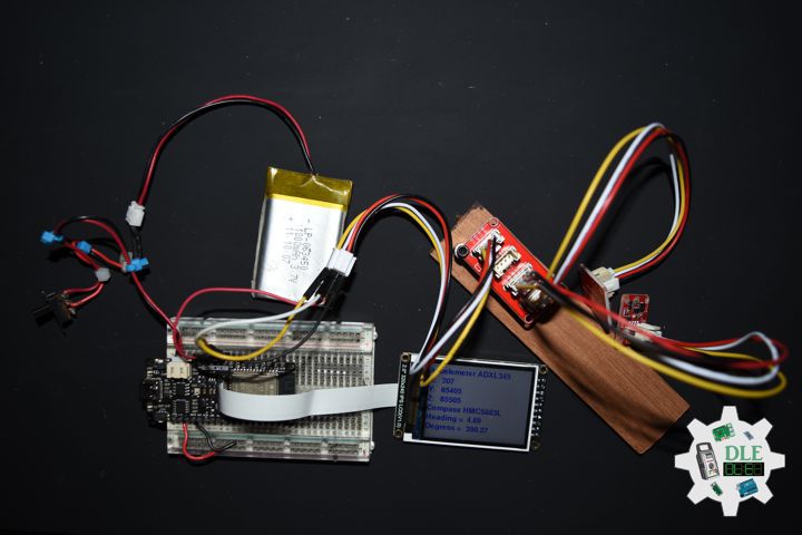
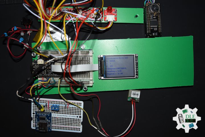
// Accelemeter and Compass, ADXL345 and HMC5883L
void isDisplayADXL345HMC5883L(){
// DFRobot Display 240x320
// Text Display
// Text Wrap
screen.setTextWrap(false);
// Rotation
screen.setRotation(3);
// Fill Screen => white
screen.fillScreen(0xffff);
// Text Color => blue
screen.setTextColor(0x001F);
// Font => Free Sans Bold 12pt
screen.setFont(&FreeSansBold12pt7b);
// TextSize => 1.5
screen.setTextSize(1.5);
// Accelemeter ADXL345
screen.setCursor(0, 30);
screen.println("Accelemeter ADXL345");
// Accelemeter ADXL345 X
screen.setCursor(0, 60);
screen.println("X: ");
screen.setCursor(40, 60);
screen.println( x );
// Accelemeter ADXL345 Y
screen.setCursor(0, 90);
screen.println( "Y: " );
screen.setCursor(40, 90);
screen.println( y );
// Accelemeter ADXL345 Z
screen.setCursor(0, 120);
screen.println( "Z: " );
screen.setCursor(40, 120);
screen.println( z );
// Compass HMC5883L
screen.setCursor(0, 150);
screen.println( "Compass HMC5883L" );
// Heading
screen.setCursor(0, 180);
screen.println( "Heading = " );
screen.setCursor(130, 180);
screen.println( heading );
// Degress
screen.setCursor(0, 210);
screen.println( "Degress = " );
screen.setCursor(130, 210);
screen.println( headingDegrees );
}
getEEPROM.ino
// EEPROM
// isUID EEPROM Unique ID
void isUID() {

  // Is Unit ID
  uid = "";
  for (int x = 0; x < 7; x++)
  {
    uid = uid + char(EEPROM.read(x));
  }

}
getGPS.ino
// GPS Receiver
// Setup GPS
void isSetupGPS() {

  // Setup GPS
  tGPS.begin(  9600 , SERIAL_8N1 , gpsRXPIN , gpsTXPIN );

}
// isGPS
void isGPS(){

  // Receives NEMA data from GPS receiver
  // This sketch displays information every time a new sentence is correctly encoded
  while ( tGPS.available() > 0)

    if (gps.encode( tGPS.read() ))
    {

       // GPS Vector Pointer Target
       displayInfo();
       // GPS Date, Time, Speed, Altitude
       displayDTS();

    }

  if (millis() > 5000 && gps.charsProcessed() < 10)
  {

     while(true);

  }

}
// GPS Vector Pointer Target
void displayInfo(){

  // Location
  if (gps.location.isValid())
  {

     // Latitude
     TargetLat = gps.location.lat();
     // Longitude
     TargetLon = gps.location.lng();
     // GPS Status 2
     GPSSt = "Yes";

  }
  else
  {

     // GPS Status 0
     GPSSt = "No";

  }

}
// GPS Date, Time, Speed, Altitude
void displayDTS(){

  // Date
  TargetDat = "";
  if (gps.date.isValid())
  {

     // Date
     // Year
     TargetDat += String(gps.date.year(), DEC);
     TargetDat += "/";
     // Month
     TargetDat += String(gps.date.month(), DEC);
     TargetDat += "/";
     // Day
     TargetDat += String(gps.date.day(), DEC);

  }

  // Time
  TargetTim = "";
  if (gps.time.isValid())
  {

     // Time
     // Hour
     TargetTim += String(gps.time.hour(), DEC);
     TargetTim += ":";
     // Minute
     TargetTim += String(gps.time.minute(), DEC);
     TargetTim += ":";
     // Secound
     TargetTim += String(gps.time.second(), DEC);

  }

  // Speed
  TargetSMS = "";
  TargetSKH = "";
  if (gps.speed.isValid())
  {

     // Speed
     // M/S
     int x = gps.speed.mps();
     TargetSMS = String( x, DEC);
     // Km/h
     int y = gps.speed.kmph();
     TargetSKH = String( y, DEC);

  }

  // Altitude
  TargetALTM = "";
  TargetALTF = "";
  if (gps.altitude.isValid())
  {

     // Altitude
     // Meters
     int z = gps.altitude.meters();
     TargetALTM = String( z, DEC);
     // Feet
     int zz = gps.altitude.feet();
     TargetALTF = String( zz, DEC);

  }

}
getRTC.ino
// RTC (Real-Time Clock)
// Setup RTC
void isSetupRTC(){

  // RTC (Real-Time Clock)
  rtc.begin();

  // RTC Lost Power
  if (rtc.lostPower()) {

    // When time needs to be set on a new device, or after a power loss, the
    // following line sets the RTC to the date & time this sketch was compiled
    rtc.adjust(DateTime(F(__DATE__), F(__TIME__)));
    // This line sets the RTC with an explicit date & time, for example to set
    // January 21, 2014 at 3am you would call:
    // rtc.adjust(DateTime(2014, 1, 21, 3, 0, 0))

  }

}
// RTC (Real-Time Clock)
void isRTC(){

  // RTC (Real-Time Clock)
  DateTime now = rtc.now();

  // Date
  dateRTC = now.year(), DEC;
  dateRTC = dateRTC + "/";
  dateRTC = dateRTC + now.month(), DEC;
  dateRTC = dateRTC + "/";
  dateRTC = dateRTC + now.day(), DEC;

  // Time
  timeRTC = now.hour(), DEC;
  timeRTC = timeRTC + ":";
  timeRTC = timeRTC + now.minute(), DEC;
  timeRTC = timeRTC + ":";
  timeRTC = timeRTC + now.second(), DEC;

  // Temperature
  tempRTC = rtc.getTemperature();

}
getSD.ino
// MicroSD Card
// MicroSD Setup
void isSetupSD() {

    // MicroSD Card
    pinMode( chipSelect , OUTPUT );
    if(!SD.begin( chipSelect )){
        ;
        return;
    }

    uint8_t cardType = SD.cardType();

    // CARD NONE
    if(cardType == CARD_NONE){
        ;
        return;
    }

    // SD Card Type
    if(cardType == CARD_MMC){
        ;
    } else if(cardType == CARD_SD){
        ;
    } else if(cardType == CARD_SDHC){
        ;
    } else {
        ;
    }

    // Size
    uint64_t cardSize = SD.cardSize() / (1024 * 1024);

}
// MicroSD Card
void isSD() {

  zzzzzz = "";

  //DLE|EEPROM Unique ID|Version|Date|Time|Temperature|
  //Accelerometer X|Accelerometer Y|Accelerometer Z|
  //Accelerometer X|Accelerometer Y|Accelerometer Z|
  //Compass Heading|Compass Degress|
  //GPS|Latitude|Longitude|GPS Date|GPS Time|
  //GPS Speed M/S|GPS Speed Km/h|
  //GPS Altitude Feet|GPS Altitude Meters|*\r
  zzzzzz = "DLE|" + uid + "|" + sver + "|" + String( dateRTC ) + "|"
  + String( timeRTC ) + "|" + String( tempRTC ) + "|"
  + String(x) + "|" + String(y) + "|" + String(z) + "|"
  + String(ax) + "|" + String(ay) + "|" + String(az) + "|"
  + String( heading ) + "|" + String( headingDegrees ) + "|"
  + String(GPSSt) + "|" + String(TargetLat) + "|" + String(TargetLon) + "|"
  + String(TargetDat) + "|" + String(TargetTim) + "|"
  + String(TargetSMS) + "|" + String(TargetSKH) + "|"
  + String(TargetALTF) + "|" + String(TargetALTM)+ "|*\r";

  // msg + 1
  char msg[zzzzzz.length() + 1];

  zzzzzz.toCharArray(msg, zzzzzz.length() + 1);

  // Append File
  appendFile(SD, "/dledata.txt", msg );

  // FullString
  // ************
  FullString = "************\r\n";
  // FullString Bluetooth Serial + Serial
  for(int i = 0; i < FullString.length(); i++)
  {

    // Bluetooth Serial
    SerialBT.write(FullString.c_str()[i]);
    // Serial
    Serial.write(FullString.c_str()[i]);

  }

  // FullString
  // zzzzzz
  FullString = zzzzzz;
  // FullString Bluetooth Serial + Serial
  for(int i = 0; i < FullString.length(); i++)
  {

    // Bluetooth Serial
    SerialBT.write(FullString.c_str()[i]);
    // Serial
    Serial.write(FullString.c_str()[i]);

  }


}
// List Dir
void listDir(fs::FS &fs, const char * dirname, uint8_t levels){

    // List Dir
    dirname;

    File root = fs.open(dirname);

    if(!root){
        return;
    }

    if(!root.isDirectory()){
        return;
    }

    File file = root.openNextFile();

    while(file){
        if(file.isDirectory()){
            file.name();
            if(levels){
                listDir(fs, file.name(), levels -1);
            }
        } else {
            file.name();
            file.size();
        }
        file = root.openNextFile();
    }

}
// Write File
void writeFile(fs::FS &fs, const char * path, const char * message){

    // Write File
    path;

    File file = fs.open(path, FILE_WRITE);

    if(!file){
        return;
    }

    if(file.print(message)){
        ;
    } else {
        ;
    }

    file.close();

}
// Append File
void appendFile(fs::FS &fs, const char * path, const char * message){

    // Append File
    path;

    File file = fs.open(path, FILE_APPEND);

    if(!file){
        return;
    }

    if(file.print(message)){
        ;
    } else {
        ;
    }

    file.close();

}
setup.ino
// Setup
void setup()
{

  // Serial Begin
  Serial.begin(115200);
  Serial.println("Starting BLE work!");

  // Bluetooth Serial
  SerialBT.begin("DL2502Mk05");
  Serial.println("Bluetooth Started! Ready to pair...");

  // Delay
  delay( 100 );

  // EEPROM Size
  EEPROM.begin(EEPROM_SIZE);

  // EEPROM Unique ID
  isUID();

  // Delay
  delay(100);

  // Wire
  Wire.begin();

  // Delay
  delay(100);

  // Setup RTC
  isSetupRTC();

  // Delay
  delay(100);

  //MicroSD Card
  isSetupSD();

  // Delay
  delay(100);

  // DFRobot Display 240x320
  screen.begin();

  // Delay
  delay(100);

  // Setup Accelemeter ADXL345
  isSetupADXL345();

  // Setup HMC5883L
  isSetupHMC5883L();

  // Delay
  delay( 100 );

  // GPS Receiver
  // Setup GPS
  isSetupGPS();

  // Delay
  delay( 100 );

  // iLED Red
  pinMode(iLED, OUTPUT);

  // LED Red LOW
  digitalWrite(iLED, LOW);

  // Delay
  delay( 100 );

  // Switch
  pinMode(iSwitch,INPUT);

  // Delay
  delay( 100 );

  // DFRobot Display 240x320 - UID
  // Don Luc Electronics
  // Version
  isDisplayUID();

  // Delay 5 Second
  delay( 5000 );

}
——
People can contact us: https://www.donluc.com/?page_id=1927
Electronics, IoT, Teacher, Instructor, R&D and Consultant
- Programming Language
- Single-Board Microcontrollers (PIC, Arduino, Raspberry Pi, Arm, Silicon Labs, Espressif, Etc…)
- IoT
- Wireless (Radio Frequency, Bluetooth, WiFi, Etc…)
- Robotics
- Automation
- Camera and Video Capture Receiver Stationary, Wheel/Tank and Underwater Vehicle
- Unmanned Vehicles Terrestrial and Marine
- Machine Learning
- Artificial Intelligence (AI)
- RTOS
- Sensors, eHealth Sensors, Biosensor, and Biometric
- Research & Development (R & D)
- Consulting
Follow Us
Luc Paquin – Curriculum Vitae – 2025
https://www.donluc.com/luc/
Web: https://www.donluc.com/
Facebook: https://www.facebook.com/neosteam.labs.9/
YouTube: https://www.youtube.com/@thesass2063
Twitter: https://twitter.com/labs_steam
Pinterest: https://www.pinterest.com/NeoSteamLabs/
Instagram: https://www.instagram.com/neosteamlabs/
Patreon: https://patreon.com/DonLucElectronics59
DFRobot: https://learn.dfrobot.com/user-10186.html
Hackster.io: https://www.hackster.io/neosteam-labs
Elecrow: https://www.elecrow.com/share/sharepj/center/no/760816d385ebb1edc0732fd873bfbf13
TikTok: https://www.tiktok.com/@luc.paquin8
Twitch: https://www.twitch.tv/lucpaquin
LinkedIn: https://www.linkedin.com/in/jlucpaquin/
Don Luc