
——
#DonLucElectronics #DonLuc #SparkFunRedBoard #Movement #MPU9150 #9DOF #Quaternion #Magnetometer #Accelerometer #Gyroscope #Arduino #Project #Fritzing #Programming #Electronics #Microcontrollers #Consultant
——
——
——
——
Quaternion
In mathematics, the quaternion number system extends the complex numbers. Quaternions were first described by the Irish mathematician William Rowan Hamilton in 1843 and applied to mechanics in three-dimensional space. Hamilton defined a quaternion as the quotient of two directed lines in a three-dimensional space, as the quotient of two vectors. Multiplication of quaternions is noncommutative.
Quaternions are used in pure mathematics, but also have practical uses in applied mathematics, particularly for calculations involving three-dimensional rotations, such as in three-dimensional computer graphics, computer vision, and crystallographic texture analysis. They can be used alongside other methods of rotation, such as Euler angles and rotation matrices, or as an alternative to them, depending on the application.
SparkFun 9 Degrees of Freedom Breakout – MPU-9150
The SparkFun 9DOF MPU-9150 is the world’s first 9-axis MotionTracking MEMS device designed for the low power, low cost, and high performance requirements of consumer electronics equipment including smartphones, tablets and wearable sensors. And guess what? You get to play with it.
This breakout board makes it easy to prototype with the InvenSense MPU-9150 by breaking out all the pins you need to standard 0.1″ spaced headers. The board also provides I2C pullup resistors and a solder jumper to switch the I2C address of the device.
The MPU-9150 is a System in Package (SiP) that combines two chips: the MPU-6050, which contains a 3-axis gyroscope, 3-axis accelerometer, and an onboard Digital Motion Processor™ (DMP™) capable of processing complex MotionFusion algorithms; and the AK8975, a 3-axis digital compass. The part’s integrated 6-axis MotionFusion algorithms access all internal sensors to gather a full set of sensor data.
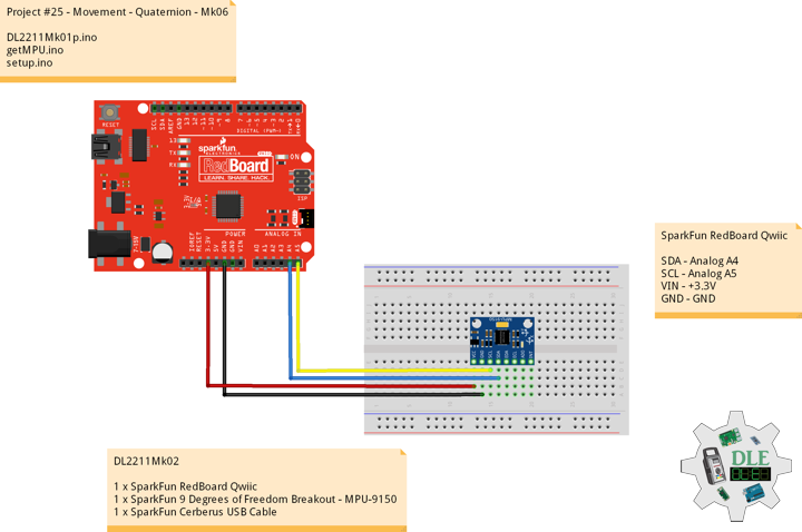
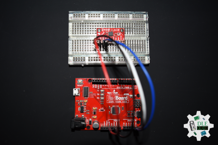
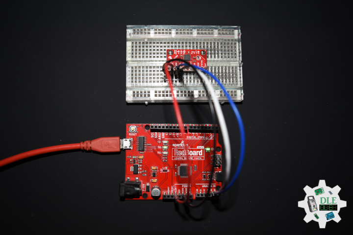
DL2211Mk02
1 x SparkFun RedBoard Qwiic
1 x SparkFun 9 Degrees of Freedom Breakout – MPU-9150
1 x SparkFun Cerberus USB Cable
SparkFun RedBoard Qwiic
SDA – Analog A4
SCL – Analog A5
VIN – +3.3V
GND – GND
——
DL2211Mk02p.ino
/* ***** Don Luc Electronics © *****
Software Version Information
Project #25 - Movement - Quaternion - Mk06
25-06
DL2211Mk02p.ino
1 x SparkFun RedBoard Qwiic
1 1 x SparkFun 9 Degrees of Freedom Breakout - MPU-9150
1 x SparkFun Cerberus USB Cable
*/

// Include the Library Code
// Two Wire Interface (TWI/I2C)
#include <Wire.h>
// I2CDev I2C utilities
#include "I2Cdev.h"
// MPU9150Lib 9-axis fusion
#include "MPU9150Lib.h"
// CalLib magnetometer and accelerometer calibration
#include "CalLib.h"
// Motion Driver InvenSense Embedded SDK v5.1
#include <dmpKey.h>
#include <dmpmap.h>
#include <inv_mpu.h>
#include <inv_mpu_dmp_motion_driver.h>
// EEPROM Magnetometer and Accelerometer data is stored
#include <EEPROM.h>

// the MPU object
MPU9150Lib MPU;
//  MPU_UPDATE_RATE defines the rate (in Hz)
// at which the MPU updates the sensor data and DMP output
#define MPU_UPDATE_RATE  (20)
//  MAG_UPDATE_RATE defines the rate (in Hz) at which the
// MPU updates the magnetometer data
//  MAG_UPDATE_RATE should be less than or equal to the MPU_UPDATE_RATE
#define MAG_UPDATE_RATE  (10)
//  MPU_MAG_MIX defines the influence that the magnetometer has on the yaw output.
//  The magnetometer itself is quite noisy so some mixing with the gyro yaw can help
//  significantly. Some example values are defined below:
// Just use gyro yaw
#define  MPU_MAG_MIX_GYRO_ONLY          0
// Just use magnetometer and no gyro yaw
#define  MPU_MAG_MIX_MAG_ONLY           1
// A good mix value
#define  MPU_MAG_MIX_GYRO_AND_MAG       10
// mainly gyros with a bit of mag correction
#define  MPU_MAG_MIX_GYRO_AND_SOME_MAG  50
//  MPU_LPF_RATE is the low pas filter rate and can be between 5 and 188Hz
#define MPU_LPF_RATE   5

// This is our earth frame gravity vector - quaternions and vectors
MPUQuaternion gravity;

//  SERIAL_PORT_SPEED defines the speed to use for the debug serial port
#define  SERIAL_PORT_SPEED  115200

// Software Version Information
String sver = "25-06";

void loop() {

  // MPU
  isMPU();

}
getMPU.ino
// MPU
// Setup MPU
void isSetupMPU() {

  // MPU
  MPU.init(MPU_UPDATE_RATE, MPU_MAG_MIX_GYRO_AND_MAG, MAG_UPDATE_RATE, MPU_LPF_RATE);     // start the MPU

  // Set up the initial gravity vector for quaternion rotation
  // Max value down the z axis
  gravity[QUAT_W] = 0;
  gravity[QUAT_X] = 0;
  gravity[QUAT_Y] = 0;
  gravity[QUAT_Z] = SENSOR_RANGE;

}
// MPU
void isMPU() {

  // Quaternion
  // This is our body frame gravity vector
  MPUQuaternion rotatedGravity;
  // This is the conjugate of the fused quaternion
  MPUQuaternion fusedConjugate;
  // Used in the rotation
  MPUQuaternion qTemp;
  // The accelerations
  MPUVector3 result;

  // Get the latest data
  if (MPU.read()) {

    // Need this for the rotation
    MPUQuaternionConjugate(MPU.m_fusedQuaternion, fusedConjugate);

    // Rotate the gravity vector into the body frame
    MPUQuaternionMultiply(gravity, MPU.m_fusedQuaternion, qTemp);
    MPUQuaternionMultiply(fusedConjugate, qTemp, rotatedGravity);

    // Now subtract rotated gravity from the body accels to get real accelerations.
    // Note that signs are reversed to get +ve acceleration results
    // in the conventional axes.
    result[VEC3_X] = -(MPU.m_calAccel[VEC3_X] - rotatedGravity[QUAT_X]);
    result[VEC3_Y] = -(MPU.m_calAccel[VEC3_Y] - rotatedGravity[QUAT_Y]);
    result[VEC3_Z] = -(MPU.m_calAccel[VEC3_Z] - rotatedGravity[QUAT_Z]);

    // print the residual accelerations
    MPU.printVector(result);
    Serial.println();

  }

}
setup.ino
// Setup
void setup() {

  // Serial
  Serial.begin(SERIAL_PORT_SPEED);
  Serial.println("Accel9150 starting");

  // Give display time to power on
  delay(100);

  // Set up I2C bus
  Wire.begin();

  // Setup MPU
  isSetupMPU();

}
——
People can contact us: https://www.donluc.com/?page_id=1927
Technology Experience
- Single-Board Microcontrollers (PIC, Arduino, Raspberry Pi,Espressif, etc…)
- IoT
- Wireless (Radio Frequency, Bluetooth, WiFi, Etc…)
- Robotics
- Camera and Video Capture Receiver Stationary, Wheel/Tank and Underwater Vehicle
- Unmanned Vehicles Terrestrial and Marine
- Machine Learning
- RTOS
- Research & Development (R & D)
Instructor and E-Mentor
- IoT
- PIC Microcontrollers
- Arduino
- Raspberry Pi
- Espressif
- Robotics
Follow Us
Luc Paquin – Curriculum Vitae – 2023
https://www.donluc.com/luc/
Web: https://www.donluc.com/
Facebook: https://www.facebook.com/neosteam.labs.9/
YouTube: https://www.youtube.com/channel/UC5eRjrGn1CqkkGfZy0jxEdA
Twitter: https://twitter.com/labs_steam
Pinterest: https://www.pinterest.com/NeoSteamLabs/
Instagram: https://www.instagram.com/neosteamlabs/
Don Luc