——
#DonLucElectronics #DonLuc #RadioFrequency #Moteino #Send #Receive #GPSReceiver #OpenLog #Display #FreeIMU #Magnetometer #Accelerometer #Gyroscope #Arduino #Project #Fritzing #Programming #Electronics #Microcontrollers #Consultant
——
——
——
——
GPS Receiver – GP-20U7 (56 Channel)
The GP-20U7 is a compact GPS receiver with a built-in high performances all-in-one GPS chipset. The GP-20U7 accurately provides position, velocity, and time readings as well possessing high sensitivity and tracking capabilities. Thanks to the low power consumption this receiver requires, the GP-20U7 is ideal for portable applications such as tablet PCs, smart phones, and other devices requiring positioning capability.
This 56-channel GPS module, that supports a standard NMEA-0183 and uBlox 7 protocol, has low power consumption of 40mA@3.3V (Max), an antenna on board, and -162dBm tracking sensitivity. With 56 channels in search mode and 22 channels “All-In-View” tracking, the GP-20U7 is quite the work horse for its size.
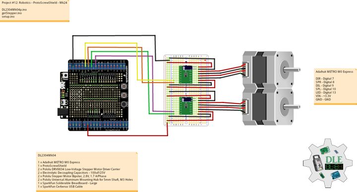
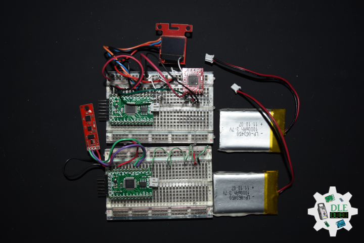
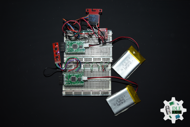
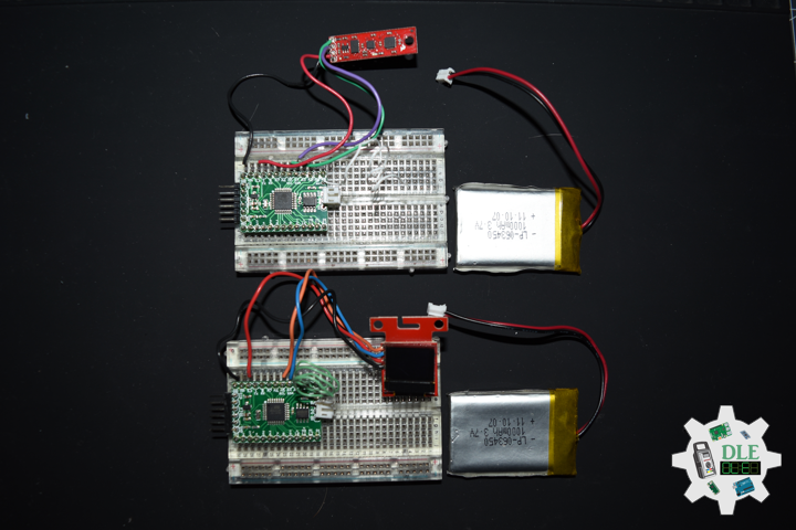
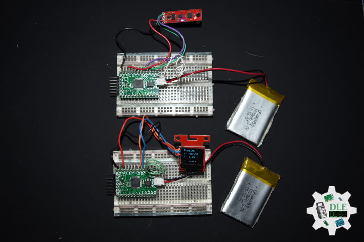
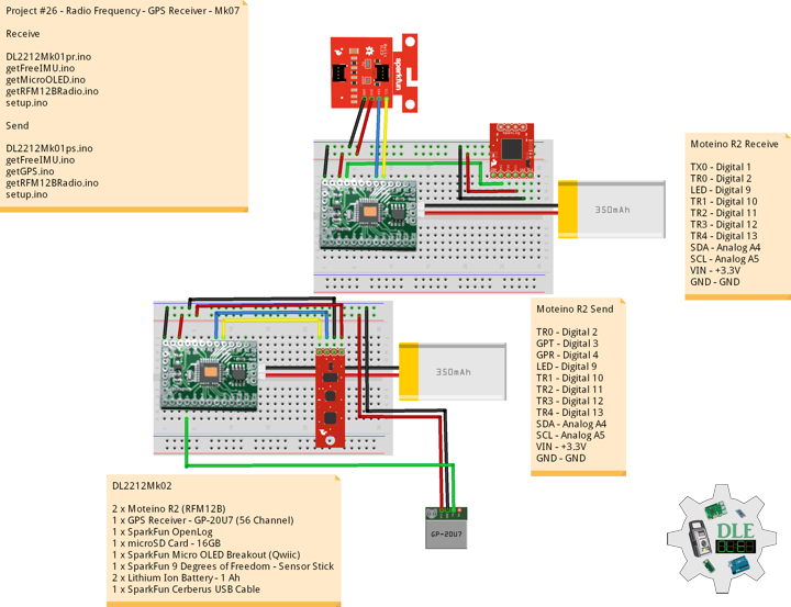
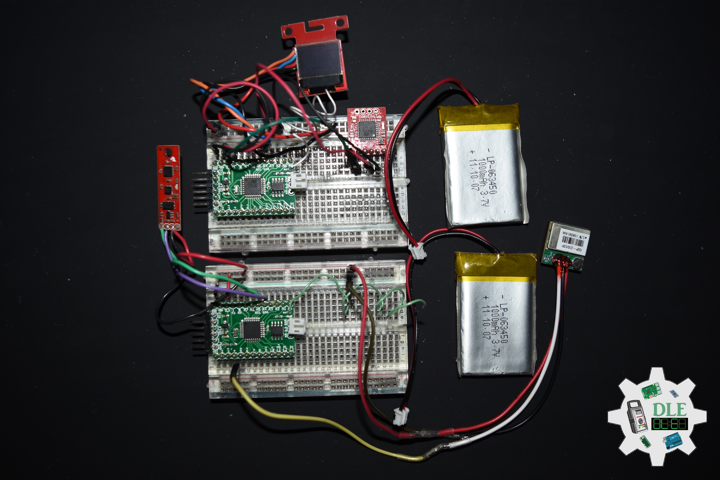
DL2212Mk02
2 x Moteino R2 (RFM12B)
1 x GPS Receiver – GP-20U7 (56 Channel)
1 x SparkFun OpenLog
1 x microSD Card – 16GB
1 x SparkFun Micro OLED Breakout (Qwiic)
1 x SparkFun 9 Degrees of Freedom – Sensor Stick
2 x Lithium Ion Battery – 1 Ah
1 x SparkFun Cerberus USB Cable
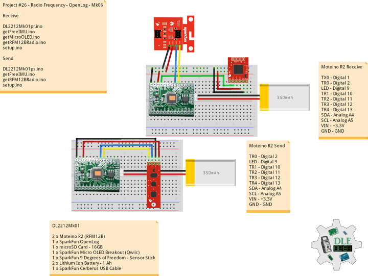
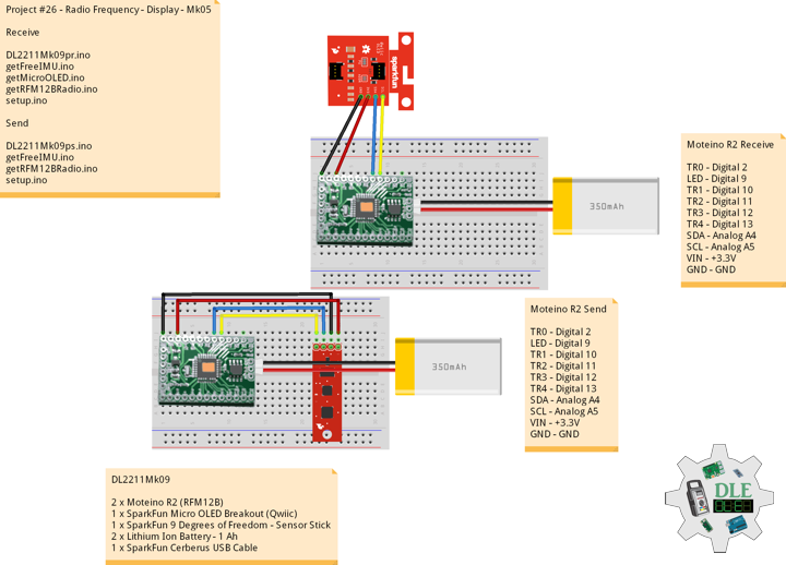
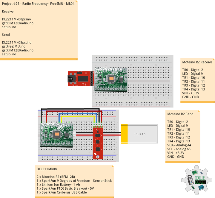
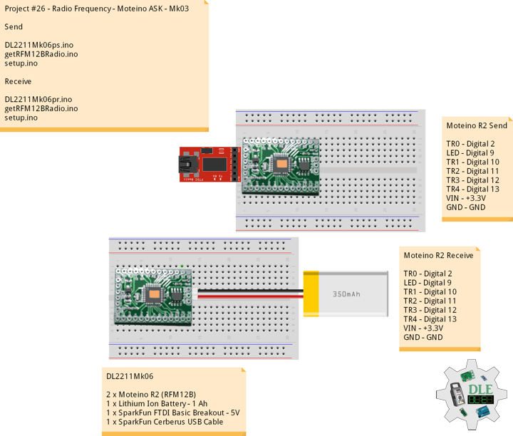
Moteino R2 (Receive)
TX0 – Digital 1
TR0 – Digital 2
LED – Digital 9
TR1 – Digital 10
TR2 – Digital 11
TR3 – Digital 12
TR4 – Digital 13
SDA – Analog A4
SCL – Analog A5
VIN – +3.3V
GND – GND
——
DL2212Mk02pr.ino
/* ***** Don Luc Electronics © *****
Software Version Information
Project #26 - Radio Frequency - GPS Receiver - Mk07
26-07
Receive
DL2212Mk02pr.ino
2 x Moteino R2 (RFM12B)
1 x GPS Receiver - GP-20U7 (56 Channel)
1 x SparkFun OpenLog
1 x microSD Card - 16GB
1 x SparkFun Micro OLED Breakout (Qwiic)
1 x SparkFun 9 Degrees of Freedom - Sensor Stick
2 x Lithium Ion Battery - 1Ah
1 x SparkFun Cerberus USB Cable
*/

// Include the Library Code
// RFM12B Radio
#include <RFM12B.h>
// Two Wire Interface (TWI/I2C)
#include <Wire.h>
// SparkFun Micro OLED
#include <SFE_MicroOLED.h>

// You will need to initialize the radio by telling it what ID
// it has and what network it's on
// The NodeID takes values from 1-127, 0 is reserved for sending
// broadcast messages (send to all nodes)
// The Network ID takes values from 0-255
// By default the SPI-SS line used is D10 on Atmega328.
// You can change it by calling .SetCS(pin) where pin can be {8,9,10}
// Network ID used for this unit
#define NODEID        1
// The network ID we are on
#define NETWORKID    99
// Serial
#define SERIAL_BAUD  115200

// Encryption is OPTIONAL
// to enable encryption you will need to:
// - provide a 16-byte encryption KEY (same on all nodes that talk encrypted)
// - to call .Encrypt(KEY) to start encrypting
// - to stop encrypting call .Encrypt(NULL)
uint8_t KEY[] = "ABCDABCDABCDABCD";

// Need an instance of the RFM12B Radio Module
RFM12B radio;

// Process Message
// Message
String msg = "";
int firstClosingBracket = 0;
// Yaw Pitch Roll
String sYaw = "";
String sPitch = "";
String sRoll = "";
float Yaw = 0;
float Pitch = 0;
float Roll = 0;

// LED
int iLED = 9;

// SparkFun Micro OLED
#define PIN_RESET 9
#define DC_JUMPER 1
// I2C declaration
MicroOLED oled(PIN_RESET, DC_JUMPER);

// Software Version Information
String sver = "26-07";

void loop() {

  // is RFM12B Radio
  isRFM12BRadio();

  // Micro OLED
  isMicroOLED();

}
getFreeIMU.ino
// FreeIMU
// isFreeIMU
void isFreeIMU(){

  // FreeIMU
  // msg = "<IMU|Yaw|Pitch|Roll|GPS Status|Latitude|Longitude|Date|Time|*"
  // msg = "<IMU|" + sYaw + "|" + sPitch + "|" + sRoll + "|" + GPSSt
  // + "|" + TargetLat + "|" TargetLon + "|" + TargetDat +"|" + TargetTim + "|*"
  firstClosingBracket = 0;
  // "<IMU|"
  firstClosingBracket = msg.indexOf('|');
  msg.remove(0, 5);
  // Yaw
  firstClosingBracket = msg.indexOf('|');
  sYaw = msg;
  sYaw.remove(firstClosingBracket);
  Yaw = sYaw.toFloat();
  // Pitch
  firstClosingBracket = firstClosingBracket + 1;
  msg.remove(0, firstClosingBracket );
  firstClosingBracket = msg.indexOf('|');
  sPitch = msg;
  sPitch.remove(firstClosingBracket);
  Pitch = sPitch.toFloat();
  // Roll
  firstClosingBracket = firstClosingBracket + 1;
  msg.remove(0, firstClosingBracket );
  firstClosingBracket = msg.indexOf('|');
  sRoll = msg;
  sRoll.remove(firstClosingBracket);
  Roll = sRoll.toFloat();

}
getMicroOLED.ino
// SparkFun Micro OLED
// Setup Micro OLED
void isSetupMicroOLED() {
// Initialize the OLED
oled.begin();
// Clear the display's internal memory
oled.clear(ALL);
// Display what's in the buffer (splashscreen)
oled.display();
// Delay 1000 ms
delay(1000);
// Clear the buffer.
oled.clear(PAGE);
}
// Micro OLED
void isMicroOLED() {
// Text Display FreeIMU
// Clear the display
oled.clear(PAGE);
// Set cursor to top-left
oled.setCursor(0, 0);
// Set font to type 0
oled.setFontType(0);
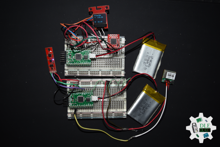
// FreeIMU
oled.print("FreeIMU");
oled.setCursor(0, 12);
// Yaw
oled.print("Y: ");
oled.print(Yaw);
oled.setCursor(0, 25);
// Pitch
oled.print("P: ");
oled.print(Pitch);
oled.setCursor(0, 39);
// Roll
oled.print("R: ");
oled.print(Roll);
oled.display();
}
getRFM12BRadio.ino
// RFM12B Radio
void isSetupRFM12BRadio()
{

  // RFM12B Radio
  radio.Initialize(NODEID, RF12_433MHZ, NETWORKID);
  // Encryption
  radio.Encrypt(KEY);
  // Transmitting

}
// is RFM12 BRadio
void isRFM12BRadio()
{

  // Receive
  if (radio.ReceiveComplete())
  {

    // CRC Pass
    if (radio.CRCPass())
    {

      // Message
      msg = "";

      // Can also use radio.GetDataLen() if you don't like pointers
      for (byte i = 0; i < *radio.DataLen; i++)
      {

       //Serial.print((char)radio.Data[i]);
        msg = msg + (char)radio.Data[i];

      }

      // Serial
      Serial.println( msg );

      // Turn the LED on HIGH
      digitalWrite( iLED , HIGH);

      // FreeIMU
      // Yaw Pitch Roll
      isFreeIMU();

      // ACK Requested
      if (radio.ACKRequested())
      {

        // Send ACK
        radio.SendACK();

      }

      // Turn the LED on LOW
      digitalWrite( iLED , LOW);

    }
    else
    {

      // BAD-CRC

    }

  }

}
setup.ino
// Setup
void setup()
{

  // Serial
  Serial.begin(SERIAL_BAUD);

  // Give display time to power on
  delay(100);

  // Set up I2C bus
  Wire.begin();

  // Setup Micro OLED
  isSetupMicroOLED();

  // LED
  pinMode( iLED , OUTPUT);

  // RFM12B Radio
  isSetupRFM12BRadio();

}
——
Moteino R2 (Send)
TR0 – Digital 2
GPT – Digital 3
GPR – Digital 4
LED – Digital 9
TR1 – Digital 10
TR2 – Digital 11
TR3 – Digital 12
TR4 – Digital 13
SDA – Analog A4
SCL – Analog A5
VIN – +3.3V
GND – GND
——
DL2212Mk02ps.ino
/* ***** Don Luc Electronics © *****
Software Version Information
Project #26 - Radio Frequency - GPS Receiver - Mk07
26-07
Send
DL2212Mk02ps.ino
2 x Moteino R2 (RFM12B)
1 x GPS Receiver - GP-20U7 (56 Channel)
1 x SparkFun OpenLog
1 x microSD Card - 16GB
1 x SparkFun Micro OLED Breakout (Qwiic)
1 x SparkFun 9 Degrees of Freedom - Sensor Stick
2 x Lithium Ion Battery - 1Ah
1 x SparkFun Cerberus USB Cable
*/

// Include the Library Code
// RFM12B Radio
#include <RFM12B.h>
// Sleep
#include <avr/sleep.h>
// Two Wire Interface (TWI/I2C)
#include <Wire.h>
// Includes and variables for IMU integration
// Accelerometer
#include <ADXL345.h>
// Magnetometer
#include <HMC58X3.h>
// MEMS Gyroscope
#include <ITG3200.h>
// Debug
#include "DebugUtils.h"
// FreeIMU
#include <CommunicationUtils.h>
#include <FreeIMU.h>
// GPS Receiver
#include <TinyGPS++.h>
// Software Serial
#include <SoftwareSerial.h>

// You will need to initialize the radio by telling it what ID
// it has and what network it's on
// The NodeID takes values from 1-127, 0 is reserved for sending
// broadcast messages (send to all nodes)
// The Network ID takes values from 0-255
// By default the SPI-SS line used is D10 on Atmega328.
// You can change it by calling .SetCS(pin) where pin can be {8,9,10}
// Network ID used for this unit
#define NODEID        2
// The network ID we are on
#define NETWORKID    99
// The node ID we're sending to
#define GATEWAYID     1
// # of ms to wait for an ack
#define ACK_TIME     50
// Serial
#define SERIAL_BAUD  115200

// Encryption is OPTIONAL
// to enable encryption you will need to:
// - provide a 16-byte encryption KEY (same on all nodes that talk encrypted)
// - to call .Encrypt(KEY) to start encrypting
// - to stop encrypting call .Encrypt(NULL)
uint8_t KEY[] = "ABCDABCDABCDABCD";

// Wait this many ms between sending packets
int interPacketDelay = 1000;
// Input
char input = 0;

// Need an instance of the RFM12B Radio Module
RFM12B radio;
// Send Size
byte sendSize = 0;
// Payload
char payload[100];
// Request ACK
bool requestACK = false;

// LED
int iLED = 9;

// Set the FreeIMU object
FreeIMU my3IMU = FreeIMU();

// Yaw Pitch Roll
String zzzzzz = "";
String sYaw = "";
String sPitch = "";
String sRoll = "";
float ypr[3];
float Yaw = 0;
float Pitch = 0;
float Roll = 0;

// GPS Receiver
#define gpsRXPIN 4
// This one is unused and doesnt have a conection
#define gpsTXPIN 3
// The TinyGPS++ object
TinyGPSPlus gps;
// Latitude
float TargetLat;
String sLat = "";
// Longitude
float TargetLon;
String sLon = "";
// GPS Date, Time
// GPS Date
String TargetDat;
// GPS Time
String TargetTim;
// GPS Status
String GPSSt = "";

// The serial connection to the GPS device
SoftwareSerial tGPS(gpsRXPIN, gpsTXPIN);

// Software Version Information
String sver = "26-07";

void loop()
{

  // isGPS
  isGPS();

  // isFreeIMU
  isFreeIMU();

  // is RFM12B Radio
  isRFM12BRadio();

  // Inter Packet Delay
  delay(interPacketDelay);

}
getFreeIMU.ino
// FreeIMU
// isFreeIMU
void isFreeIMU(){

  // FreeIMU
  // Yaw Pitch Roll
  my3IMU.getYawPitchRoll(ypr);
  // Yaw
  Yaw = ypr[0];
  // Pitch
  Pitch = ypr[1];
  // Roll
  Roll = ypr[2];

}
getGPS.ino
// GPS Receiver
// Setup GPS
void setupGPS() {

  // Setup GPS
  tGPS.begin( 9600 );

}
// isGPS
void isGPS(){

  // Receives NEMA data from GPS receiver
  // This sketch displays information every time a new sentence is correctly encoded
  while ( tGPS.available() > 0)

    if (gps.encode( tGPS.read() ))
    {

       // GPS Vector Pointer Target
       displayInfo();
       // GPS Date, Time
       displayDTS();

    }

  if (millis() > 5000 && gps.charsProcessed() < 10)
  {

     while(true);

  }

}
// GPS Vector Pointer Target
void displayInfo(){

  // Location
  if (gps.location.isValid())
  {

     // Latitude
     TargetLat = gps.location.lat();
     // Longitude
     TargetLon = gps.location.lng();
     // GPS Status 2
     GPSSt = "Yes";

  }
  else
  {

     // GPS Status 0
     GPSSt = "No";

  }

}
// GPS Date, Time
void displayDTS(){

  // Date
  TargetDat = "";
  if (gps.date.isValid())
  {

     // Date
     // Year
     TargetDat += String(gps.date.year(), DEC);
     TargetDat += "/";
     // Month
     TargetDat += String(gps.date.month(), DEC);
     TargetDat += "/";
     // Day
     TargetDat += String(gps.date.day(), DEC);

  }

  // Time
  TargetTim = "";
  if (gps.time.isValid())
  {

     // Time
     // Hour
     TargetTim += String(gps.time.hour(), DEC);
     TargetTim += ":";
     // Minute
     TargetTim += String(gps.time.minute(), DEC);
     TargetTim += ":";
     // Secound
     TargetTim += String(gps.time.second(), DEC);

  }

}
getRFM12BRadio.ino
// RFM12B Radio
void isSetupRFM12BRadio(){

  // RFM12B Radio
  radio.Initialize(NODEID, RF12_433MHZ, NETWORKID);
  // Encryption
  radio.Encrypt(KEY);
  // Sleep right away to save power
  radio.Sleep();
  // Transmitting
  Serial.println("Transmitting...\n\n");

}
// is RFM12 BRadio
void isRFM12BRadio(){

  // sYaw, sPitch, sRoll ""
  sYaw = "";
  sPitch = "";
  sRoll = "";
  // Latitude and Longitude
  sLat = "";
  sLon = "";

  // sYaw, sPitch, sRoll concat
  sYaw.concat(Yaw);
  sPitch.concat(Pitch);
  sRoll.concat(Roll);

  // Latitude and Longitude
  sLat.concat( TargetLat );
  sLon.concat( TargetLon );

  // zzzzzz ""
  zzzzzz = "";

  // zzzzzz = "<IMU|Yaw|Pitch|Roll|GPS Status|Latitude|Longitude|Date|Time|*"
  // zzzzzz = "<IMU|" + sYaw + "|" + sPitch + "|" + sRoll + "|" + GPSSt
  // + "|" + TargetLat + "|" TargetLon + "|" + TargetDat +"|" + TargetTim + "|*"
  zzzzzz = "<IMU|" + sYaw + "|" + sPitch + "|" + sRoll + "|" + GPSSt + "|"
  + sLat + "|" + sLon + "|" + TargetDat + "|" + TargetTim + "|*";

  // sendSize Length
  sendSize = zzzzzz.length();

  // sendSize
  payload[sendSize];

  // sendSize, charAt
  for(byte i = 0; i < sendSize+1; i++){

    payload[i] = zzzzzz.charAt(i);

  }

  // payload
  Serial.print(payload);

  // Request ACK
  requestACK = sendSize;

  // Wakeup
  radio.Wakeup();

  // Turn the LED on HIGH
  digitalWrite( iLED , HIGH);

  // Send
  radio.Send(GATEWAYID, payload, sendSize, requestACK);

  // Request ACK
  if (requestACK)
  {

    Serial.print(" - waiting for ACK...");
    if (waitForAck()){

      Serial.print("Ok!");

    }
    else Serial.print("nothing...");

  }

  // Turn the LED on LOW
  digitalWrite( iLED , LOW);

  // Sleep
  radio.Sleep();

  // Serial
  Serial.println();

}
// Wait a few milliseconds for proper ACK, return true if received
static bool waitForAck(){

  // Now
  long now = millis();

  // ACK
  while (millis() - now <= ACK_TIME){


    if (radio.ACKReceived(GATEWAYID)){

      return true;

    }

  }

  return false;

}
setup.ino
// Setup
void setup(){

  // Serial
  Serial.begin(SERIAL_BAUD);

  // GPS Receiver
  // Setup GPS
  setupGPS();

  // LED
  pinMode( iLED , OUTPUT);

  // Set up I2C bus
  Wire.begin();

  // RFM12B Radio
  isSetupRFM12BRadio();

  // Pause
  delay(5);
  // Initialize IMU
  my3IMU.init();
  // Pause
  delay(5);

}
——
People can contact us: https://www.donluc.com/?page_id=1927
Technology Experience
- Programming Language
- Single-Board Microcontrollers (PIC, Arduino, Raspberry Pi,Espressif, etc…)
- IoT
- Wireless (Radio Frequency, Bluetooth, WiFi, Etc…)
- Robotics
- Camera and Video Capture Receiver Stationary, Wheel/Tank and Underwater Vehicle
- Unmanned Vehicles Terrestrial and Marine
- Machine Learning
- RTOS
- Research & Development (R & D)
Instructor, E-Mentor, STEAM, and Arts-Based Training
- Programming Language
- IoT
- PIC Microcontrollers
- Arduino
- Raspberry Pi
- Espressif
- Robotics
Follow Us
Luc Paquin – Curriculum Vitae – 2023
https://www.donluc.com/luc/
Web: https://www.donluc.com/
Facebook: https://www.facebook.com/neosteam.labs.9/
YouTube: https://www.youtube.com/@thesass2063
Twitter: https://twitter.com/labs_steam
Pinterest: https://www.pinterest.com/NeoSteamLabs/
Instagram: https://www.instagram.com/neosteamlabs/
Don Luc