The Alpha Geek – Geeking Out

ArduiNIX

Project #21 – Nixie – DS3231 Precision RTC – Mk03

——

#DonLucElectronics #DonLuc #NixieTube #Nixie #ArduiNIX #ArduinoUNO #Arduino #Project #Fritzing #Programming #Electronics #Microcontrollers #Consultant

——

DS3231 Precision RTC

——

DS3231 Precision RTC

——

DS3231 Precision RTC

——

DS3231 Precision RTC FeatherWing

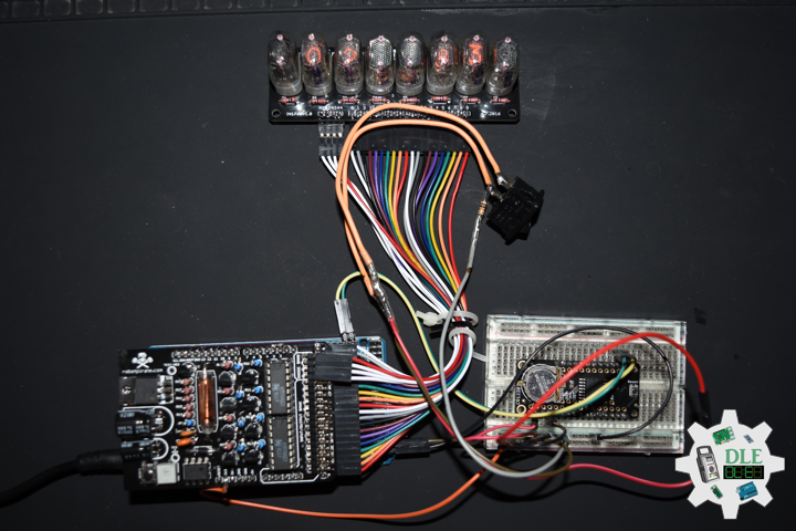
The datasheet for the DS3231 explains that this part is an extremely accurate I²C – Integrated RTC TCXO – crystal. This Real Time Clock (RTC) is the most precise you can get in a small, low power package. Most RTC’s use an external 32kHz timing crystal that is used to keep time with low current draw. That’s all well and good, but those crystals have slight drift, particularly when the temperature changes, the temperature changes the oscillation frequency very slightly but it does add up. This RTC is in a beefy package because the crystal is inside the chip. And right next to the integrated crystal is a temperature sensor. That sensor compensates for the frequency changes by adding or removing clock ticks so that the time keeping stays on schedule.

This is the finest RTC you can get, and now we have it in a compact, breadboard friendly breakout. With a coin cell plugged into the back, you can get years of precision time keeping, even when main power is lost. Great for datalogging and clocks, or anything where you need to really know the time.

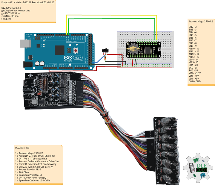
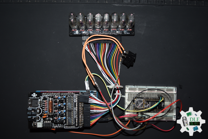
DL2209Mk03

1 x Arduino Mega 2560 R2
1 x ArduiNIX V3 Tube Driver Shield Kit
1 x IN-17×8 V1 Tube Board Kit
1 x Anode / Cathode Connector Cable Set
1 x DS3231 Precision RTC FeatherWing
1 x CR1220 12mm Coin Cell Battery
1 x Rocker Switch – SPST
1 x 10K Ohm
1 x SparkFun ProtoShield
1 x 9V 1000mA Power Supply
1 x SparkFun Cerberus USB Cable

Arduino Mega 2560 R2

SN2 – 2
SN3 – 3
SN4 – 4
SN5 – 5
SN6 – 6
SN7 – 7
SN8 – 8
SN9 – 9
AN10 – 10
AN11 – 11
AN12 – 12
AN13 – 13
VI14 – 14
VI15 – 15
SDA – 20
SCL – 21
RO0 – 53
VIN – +3.3V
VIN – +5V
VIN – +9V
GND – GND

DL2209Mk03p.ino

/* ***** Don Luc Electronics © *****
Software Version Information
Project #21 - Nixie - DS3231 Precision RTC - Mk03
21-03
DL2209Mk03p.ino
1 x Arduino Mega 2560 R2
1 x ArduiNIX V3 Tube Driver Shield Kit
1 x IN-17x8 V1 Tube Board Kit
1 x Anode / Cathode Connector Cable Set
1 x DS3231 Precision RTC FeatherWing
1 x CR1220 12mm Coin Cell Battery
1 x Rocker Switch - SPST
1 x 10K Ohm
1 x 9V 1000mA Power Supply
1 x SparkFun Cerberus USB Cable
*/

// Include the Library Code
// Wire you to communicate with I2C/TWI devices
// Date and Time DS3231 RTC
#include "RTClib.h"

// SN74141 (1)
int ledPin_0_a = 2;                
int ledPin_0_b = 3;
int ledPin_0_c = 4;
int ledPin_0_d = 5;

// SN74141 (2)
int ledPin_1_a = 6;                
int ledPin_1_b = 7;
int ledPin_1_c = 8;
int ledPin_1_d = 9;

// Anode pins
int ledPin_a_1 = 10;
int ledPin_a_2 = 11;
int ledPin_a_3 = 12;
int ledPin_a_4 = 13;

// NOTE: Grounding on virtual pins 14 and 15 
// (analog pins 0 and 1) will set the Hour and Mins.
int iVirtual14 = 14;
int iVirtual15 = 15;

// Fade
float fadeMax = 0.1f;
float fadeStep = 0.1f;
// Number Array
int NumberArray[8]={0,0,0,0,0,0,0,0};
int currNumberArray[8]={0,0,0,0,0,0,0,0};
float NumberArrayFadeInValue[8]={0.0f,0.0f,0.0f,0.0f,0.0f,0.0f,0.0f,0.0f};
float NumberArrayFadeOutValue[8]={5.0f,5.0f,5.0f,5.0f,5.0f,5.0f,5.0f,5.0f};

// Date and time functions using a DS3231 RTC
RTC_DS3231 RTC;

// Rocker Switch - SPST
int iRO0 = 53;
// State
int iRO0State = 0;

// Software Version Information
String sver = "21-03";

void loop() {

  // timeRTC
  timeRTC();

}

getDisplayFadeNumber.ino

// Display Fade Number
void DisplayFadeNumberString()
{
 
  // Anode channel 1 - numerals 0,4
  SetSN74141Chips(currNumberArray[0],currNumberArray[4]);   
  digitalWrite(ledPin_a_1, HIGH);   
  delay(NumberArrayFadeOutValue[0]);
  SetSN74141Chips(NumberArray[0],NumberArray[4]);   
  delay(NumberArrayFadeInValue[0]);
  digitalWrite(ledPin_a_1, LOW);
  
  // Anode channel 2 - numerals 1,5
  SetSN74141Chips(currNumberArray[1],currNumberArray[5]);   
  digitalWrite(ledPin_a_2, HIGH);   
  delay(NumberArrayFadeOutValue[1]);
  SetSN74141Chips(NumberArray[1],NumberArray[5]);   
  delay(NumberArrayFadeInValue[1]);
  digitalWrite(ledPin_a_2, LOW);
  
  // Anode channel 3 - numerals 2,6
  SetSN74141Chips(currNumberArray[2],currNumberArray[6]);   
  digitalWrite(ledPin_a_3, HIGH);   
  delay(NumberArrayFadeOutValue[2]);
  SetSN74141Chips(NumberArray[2],NumberArray[6]);   
  delay(NumberArrayFadeInValue[2]);
  digitalWrite(ledPin_a_3, LOW);
  
  // Anode channel 4 - numerals 3,7
  SetSN74141Chips(currNumberArray[3],currNumberArray[7]);   
  digitalWrite(ledPin_a_4, HIGH);   
  delay(NumberArrayFadeOutValue[3]);
  SetSN74141Chips(NumberArray[3],NumberArray[7]);   
  delay(NumberArrayFadeInValue[3]);
  digitalWrite(ledPin_a_4, LOW);
  
  // Loop thru and update all the arrays, and fades.
  for( int i = 0 ; i < 8 ; i ++ ) //equal to & of digits
  {
    if( NumberArray[i] != currNumberArray[i] )
    {
      NumberArrayFadeInValue[i] += fadeStep;
      NumberArrayFadeOutValue[i] -= fadeStep;
  
      if( NumberArrayFadeInValue[i] >= fadeMax )
      {
        NumberArrayFadeInValue[i] = 2.0f;
        NumberArrayFadeOutValue[i] = 4.0f; //affects the refresh cycle
        currNumberArray[i] = NumberArray[i];
      }
    }
  }
  
}

getRTCDS3231.ino

// DS3231 Precision RTC
// Setup RTC
void setupRTC() {

  // DS3231 Precision RTC   
  RTC.begin();
  if (! RTC.begin() ) {
    while (1) delay(10);
  }

  if (RTC.lostPower()) {
    
    // Following line sets the RTC to the date & time this sketch was compiled
    RTC.adjust(DateTime(F(__DATE__), F(__TIME__)));
    // This line sets the RTC with an explicit date & time, for example to set
    // August 2, 2021 at 13:53:0 you would call:
    // RTC.adjust(DateTime(2022, 4, 26, 11, 39, 0));
    
  }
  
}
// timeRTC
void timeRTC() {

  // Date and Time
  DateTime now = RTC.now();

  // Read the state of the Switch value
  iRO0State = digitalRead(iRO0);
  
  // If it is the Switch State is HIGH
  if (iRO0State == HIGH) {


    // Get the high and low order values for hours, minute, seconds
    int lowerHours = now.hour() % 10;
    int upperHours = now.hour() - lowerHours;
    int lowerMins = now.minute() % 10;
    int upperMins = now.minute() - lowerMins;
    int lowerSeconds = now.second() % 10;
    int upperSeconds = now.second() - lowerSeconds;
    
    // 10 >= hours, minute, seconds
    if( upperSeconds >= 10 )   upperSeconds = upperSeconds / 10;
    if( upperMins >= 10 )      upperMins = upperMins / 10;
    if( upperHours >= 10 )     upperHours = upperHours / 10;
    if( upperHours == 0 && lowerHours == 0 )
    {
      
      upperHours = 1;
      lowerHours = 2;
      
    }

    // Fill in the Number array used to display on the Nixie tubes
    NumberArray[7] = upperHours;
    NumberArray[6] = lowerHours;
    NumberArray[5] = 0;
    NumberArray[4] = upperMins;
    NumberArray[3] = lowerMins;
    NumberArray[2] = 0;
    NumberArray[1] = upperSeconds; 
    NumberArray[0] = lowerSeconds;

  } else {

    // Get the high and low order values for year, month, day
    int iYear = now.year() - 2000;
    int lowerYear = iYear % 10;
    int upperYear = iYear - lowerYear;
    int lowerMonth = now.month() % 10;
    int upperMonth = now.month() - lowerMonth;
    int lowerDay = now.day() % 10;
    int upperDay = now.day() - lowerDay;

    // 10 >= year, month, day
    if( upperDay >= 10 )   upperDay = upperDay / 10;
    if( upperMonth >= 10 )      upperMonth = upperMonth / 10;
    if( upperYear >= 10 )     upperYear = upperYear / 10;

    // Fill in the Number array used to display on the Nixie tubes
    NumberArray[7] = 2;
    NumberArray[6] = 0;
    NumberArray[5] = upperYear;
    NumberArray[4] = lowerYear;
    NumberArray[3] = upperMonth;
    NumberArray[2] = lowerMonth;
    NumberArray[1] = upperDay; 
    NumberArray[0] = lowerDay;
  
  }
  
  // Display
  DisplayFadeNumberString();
  
}

getSN74141.ino

// SN74141
// SN74141 : Truth Table
//D C B A #
//L,L,L,L 0
//L,L,L,H 1
//L,L,H,L 2
//L,L,H,H 3
//L,H,L,L 4
//L,H,L,H 5
//L,H,H,L 6
//L,H,H,H 7
//H,L,L,L 8
//H,L,L,H 9
// isSetupSN74141
void isSetupSN74141(){

  pinMode(ledPin_0_a, OUTPUT);      
  pinMode(ledPin_0_b, OUTPUT);      
  pinMode(ledPin_0_c, OUTPUT);      
  pinMode(ledPin_0_d, OUTPUT);    
  
  pinMode(ledPin_1_a, OUTPUT);      
  pinMode(ledPin_1_b, OUTPUT);      
  pinMode(ledPin_1_c, OUTPUT);      
  pinMode(ledPin_1_d, OUTPUT);      
  
  pinMode(ledPin_a_1, OUTPUT);      
  pinMode(ledPin_a_2, OUTPUT);      
  pinMode(ledPin_a_3, OUTPUT);   
  pinMode(ledPin_a_4, OUTPUT);    
 
  // NOTE: Grounding on virtual pins 14 and 15 
  // (analog pins 0 and 1) will set the Hour and Mins.
  // Set the vertual pin 14 (pin 0 on the analog inputs )
  pinMode( iVirtual14, INPUT );
  // Set pin 14 as a pull up resistor.
  digitalWrite(iVirtual14, HIGH);
  // Set the vertual pin 15 (pin 1 on the analog inputs )
  pinMode( iVirtual15, INPUT );
  // Set pin 15 as a pull up resistor.
  digitalWrite(iVirtual15, HIGH);
  
}
// SetSN74141Chips
void SetSN74141Chips( int num2, int num1 )
{
  
  // Set defaults
  // Will display a zero.
  int a = 0;
  int b = 0;
  int c = 0;
  int d = 0;
  
  // Load the a,b,c,d.. to send to the SN74141 IC (1)
  switch( num1 )
  {
    case 0:
      a=0;
      b=0;
      c=0;
      d=0;
      break;
    case 1:
      a=1;
      b=0;
      c=0;
      d=0;
      break;
    case 2:
      a=0;
      b=1;
      c=0;
      d=0;
      break;
    case 3:
      a=1;
      b=1;
      c=0;
      d=0;
      break;
    case 4:
      a=0;
      b=0;
      c=1;
      d=0;
      break;
    case 5:
      a=1;
      b=0;
      c=1;
      d=0;
      break;
    case 6: 
      a=0;
      b=1;
      c=1;
      d=0;
      break;
    case 7:
      a=1;
      b=1;
      c=1;
      d=0;
      break;
    case 8:
      a=0;
      b=0;
      c=0;
      d=1;
      break;
    case 9:
      a=1;
      b=0;
      c=0;
      d=1;
      break;
    default:
      a=1;
      b=1;
      c=1;
      d=1;
      break;
  }  
  
  // Write to output pins.
  digitalWrite(ledPin_0_d, d);
  digitalWrite(ledPin_0_c, c);
  digitalWrite(ledPin_0_b, b);
  digitalWrite(ledPin_0_a, a);

  // Load the a,b,c,d.. to send to the SN74141 IC (2)
  switch( num2 )
  {
    case 0:
      a=0;
      b=0;
      c=0;
      d=0;
      break;
    case 1:
      a=1;
      b=0;
      c=0;
      d=0;
      break;
    case 2:
      a=0;
      b=1;
      c=0;
      d=0;
      break;
    case 3:
      a=1;
      b=1;
      c=0;
      d=0;
      break;
    case 4:
      a=0;
      b=0;
      c=1;
      d=0;
      break;
    case 5:
      a=1;
      b=0;
      c=1;
      d=0;
      break;
    case 6:
      a=0;
      b=1;
      c=1;
      d=0;
      break;
    case 7:
      a=1;
      b=1;
      c=1;
      d=0;
      break;
    case 8:
      a=0;
      b=0;
      c=0;
      d=1;
      break;
    case 9:
      a=1;
      b=0;
      c=0;
      d=1;
      break;
    default:
      a=1;
      b=1;
      c=1;
      d=1;
      break;
  }
  
  // Write to output pins
  digitalWrite(ledPin_1_d, d);
  digitalWrite(ledPin_1_c, c);
  digitalWrite(ledPin_1_b, b);
  digitalWrite(ledPin_1_a, a);
  
}

setup.ino

// Setup
void setup() {

  // isSetupSN74141
  isSetupSN74141();

  // Switch
  pinMode(iRO0, INPUT);

  // Setup RTC
  setupRTC();

}

——

People can contact us: https://www.donluc.com/?page_id=1927

Technology Experience

  • Single-Board Microcontrollers (PIC, Arduino, Raspberry Pi,Espressif, etc…)
  • IoT
  • Robotics
  • Camera and Video Capture Receiver Stationary, Wheel/Tank and Underwater Vehicle
  • Unmanned Vehicles Terrestrial and Marine
  • Research & Development (R & D)

Instructor and E-Mentor

  • IoT
  • PIC Microcontrollers
  • Arduino
  • Raspberry Pi
  • Espressif
  • Robotics

Follow Us

J. Luc Paquin – Curriculum Vitae – 2022 English & Español
https://www.jlpconsultants.com/luc/

Web: https://www.donluc.com/
Web: https://www.jlpconsultants.com/
Facebook: https://www.facebook.com/neosteam.labs.9/
YouTube: https://www.youtube.com/channel/UC5eRjrGn1CqkkGfZy0jxEdA
Twitter: https://twitter.com/labs_steam
Pinterest: https://www.pinterest.com/NeoSteamLabs/
Instagram: https://www.instagram.com/neosteamlabs/

Don Luc
Project #21 – Nixie – ArduiNIX – Mk02

——

#DonLucElectronics #DonLuc #NixieTube #Nixie #ArduiNIX #ArduinoUNO #Arduino #Project #Fritzing #Programming #Electronics #Microcontrollers #Consultant

——

ArduiNIX

——

ArduiNIX

——

ArduiNIX

——

ArduiNIX

——

ArduiNIX

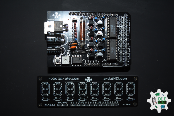
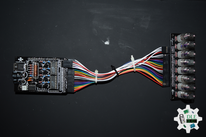
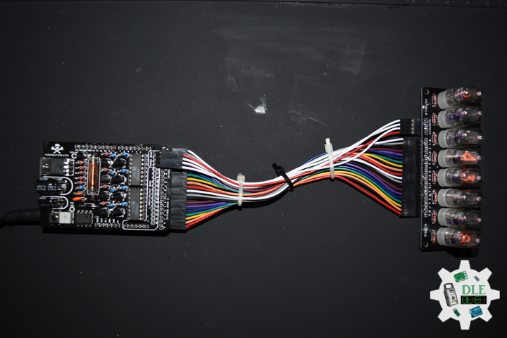
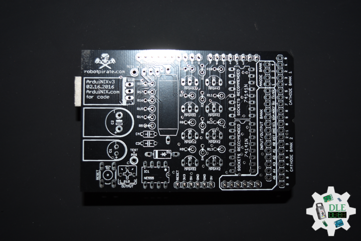
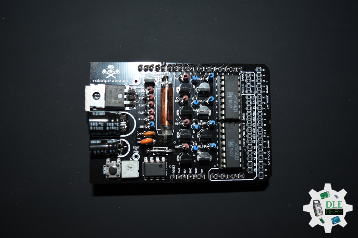
The ArduiNIX is an Arduino compatible shield which plugs right onto the top of the Arduino UNO board. ArduiNIX takes care of stepping power from 9 VDC wall adapter power supply up to a maximum of approximately 250 VDC to drive any and all Nixie tubes. ArduiNIX also provides Multiplexed display for up to 80 elements by using 4 anode channels and 20 cathode channels. Multiplexing increases the life expectancy of your Nixie tube investment.

Not only does the ArduiNIX provide a Nixie tube platform for standard clock functions, but it is also user programmable, meaning if you can program it using the arduino environment, you can make it happen on your Nixie display. Take special care when working with the ArduiNIX. The ArduiNIX Shield operates at high voltages. Be careful when handling it while it’s powered up. Normally the Arduino is safe to handle, but when used in conjunction with the ArduiNIX, voltages in excess of 200 volts may be achieved. Use caution. An IN-17 x 8 display board, and 8 x Russian IN-17 Nixie tubes.

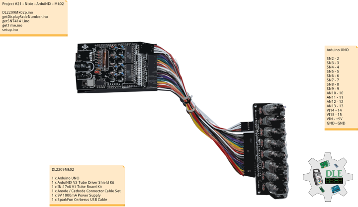
DL2209Mk02

1 x Arduino UNO
1 x ArduiNIX V3 Tube Driver Shield Kit
1 x IN-17×8 V1 Tube Board Kit
1 x Anode / Cathode Connector Cable Set
1 x 9V 1000mA Power Supply
1 x SparkFun Cerberus USB Cable

Arduino UNO

SN2 – 2
SN3 – 3
SN4 – 4
SN5 – 5
SN6 – 6
SN7 – 7
SN8 – 8
SN9 – 9
AN10 – 10
AN11 – 11
AN12 – 12
AN13 – 13
VI14 – 14
VI15 – 15
VIN – +9V
GND – GND

DL2209Mk02p.ino

/* ***** Don Luc Electronics © *****
Software Version Information
Project #21 - Nixie - ArduiNIX - Mk02
21-02
DL2209Mk02p.ino
1 x Arduino UNO
1 x ArduiNIX V3 Tube Driver Shield Kit
1 x IN-17x8 V1 Tube Board Kit
1 x Anode / Cathode Connector Cable Set
1 x 9V 1000mA Power Supply
1 x SparkFun Cerberus USB Cable
*/

// Include the Library Code

// SN74141 (1)
int ledPin_0_a = 2;                
int ledPin_0_b = 3;
int ledPin_0_c = 4;
int ledPin_0_d = 5;

// SN74141 (2)
int ledPin_1_a = 6;                
int ledPin_1_b = 7;
int ledPin_1_c = 8;
int ledPin_1_d = 9;

// Anode pins
int ledPin_a_1 = 10;
int ledPin_a_2 = 11;
int ledPin_a_3 = 12;
int ledPin_a_4 = 13;

// NOTE: Grounding on virtual pins 14 and 15 
// (analog pins 0 and 1) will set the Hour and Mins.
int iVirtual14 = 14;
int iVirtual15 = 15;

// Fade
float fadeMax = 0.1f;
float fadeStep = 0.1f;
// Number Array
int NumberArray[8]={0,0,0,0,0,0,0,0};
int currNumberArray[8]={0,0,0,0,0,0,0,0};
float NumberArrayFadeInValue[8]={0.0f,0.0f,0.0f,0.0f,0.0f,0.0f,0.0f,0.0f};
float NumberArrayFadeOutValue[8]={5.0f,5.0f,5.0f,5.0f,5.0f,5.0f,5.0f,5.0f};

// Defines
// Sub seconds
long SSECS = 100;
// Milliseconds in a Sec
long SECS = 60;
// 60 Seconds in a Min.
long MINS = 60;
// 60 Mins in an hour
long HOURS = 60 * MINS;
// 24 Hours in a day. > Note: change the 24 to a 12 for non military time.
long DAYS = 12 * HOURS; 

// Time from when we started
long runTime = 0;

// Default time sets. clock will start at 12:34:00.
// This is so we can count the correct order of tubes.
long clockHourSet;
long clockMinSet;
long clockSecSet;
//long clockSSecSet;

int HourButtonPressed = false;
int MinButtonPressed = false;

// Software Version Information
String sver = "21-02";

void loop() {

  // Time
  isTime();
  
}

getDisplayFadeNumber.ino

// Display Fade Number
void DisplayFadeNumberString()
{
 
  // Anode channel 1 - numerals 0,4
  SetSN74141Chips(currNumberArray[0],currNumberArray[4]);   
  digitalWrite(ledPin_a_1, HIGH);   
  delay(NumberArrayFadeOutValue[0]);
  SetSN74141Chips(NumberArray[0],NumberArray[4]);   
  delay(NumberArrayFadeInValue[0]);
  digitalWrite(ledPin_a_1, LOW);
  
    // Anode channel 2 - numerals 1,5
  SetSN74141Chips(currNumberArray[1],currNumberArray[5]);   
  digitalWrite(ledPin_a_2, HIGH);   
  delay(NumberArrayFadeOutValue[1]);
  SetSN74141Chips(NumberArray[1],NumberArray[5]);   
  delay(NumberArrayFadeInValue[1]);
  digitalWrite(ledPin_a_2, LOW);
  
   // Anode channel 3 - numerals 2,6
  SetSN74141Chips(currNumberArray[2],currNumberArray[6]);   
  digitalWrite(ledPin_a_3, HIGH);   
  delay(NumberArrayFadeOutValue[2]);
  SetSN74141Chips(NumberArray[2],NumberArray[6]);   
  delay(NumberArrayFadeInValue[2]);
  digitalWrite(ledPin_a_3, LOW);
  
     // Anode channel 4 - numerals 3,7
  SetSN74141Chips(currNumberArray[3],currNumberArray[7]);   
  digitalWrite(ledPin_a_4, HIGH);   
  delay(NumberArrayFadeOutValue[3]);
  SetSN74141Chips(NumberArray[3],NumberArray[7]);   
  delay(NumberArrayFadeInValue[3]);
  digitalWrite(ledPin_a_4, LOW);
  
  // Loop thru and update all the arrays, and fades.
  for( int i = 0 ; i < 8 ; i ++ ) //equal to & of digits
  {
    if( NumberArray[i] != currNumberArray[i] )
    {
      NumberArrayFadeInValue[i] += fadeStep;
      NumberArrayFadeOutValue[i] -= fadeStep;
  
      if( NumberArrayFadeInValue[i] >= fadeMax )
      {
        NumberArrayFadeInValue[i] = 2.0f;
        NumberArrayFadeOutValue[i] = 4.0f; //affects the refresh cycle
        currNumberArray[i] = NumberArray[i];
      }
    }
  }
  
}

getSN74141.ino

// SN74141
// SN74141 : Truth Table
//D C B A #
//L,L,L,L 0
//L,L,L,H 1
//L,L,H,L 2
//L,L,H,H 3
//L,H,L,L 4
//L,H,L,H 5
//L,H,H,L 6
//L,H,H,H 7
//H,L,L,L 8
//H,L,L,H 9
// isSetupSN74141
void isSetupSN74141(){

  pinMode(ledPin_0_a, OUTPUT);      
  pinMode(ledPin_0_b, OUTPUT);      
  pinMode(ledPin_0_c, OUTPUT);      
  pinMode(ledPin_0_d, OUTPUT);    
  
  pinMode(ledPin_1_a, OUTPUT);      
  pinMode(ledPin_1_b, OUTPUT);      
  pinMode(ledPin_1_c, OUTPUT);      
  pinMode(ledPin_1_d, OUTPUT);      
  
  pinMode(ledPin_a_1, OUTPUT);      
  pinMode(ledPin_a_2, OUTPUT);      
  pinMode(ledPin_a_3, OUTPUT);   
  pinMode(ledPin_a_4, OUTPUT);    
 
  // NOTE: Grounding on virtual pins 14 and 15 
  // (analog pins 0 and 1) will set the Hour and Mins.
  // Set the vertual pin 14 (pin 0 on the analog inputs )
  pinMode( iVirtual14, INPUT );
  // Set pin 14 as a pull up resistor.
  digitalWrite(iVirtual14, HIGH);
  // Set the vertual pin 15 (pin 1 on the analog inputs )
  pinMode( iVirtual15, INPUT );
  // Set pin 15 as a pull up resistor.
  digitalWrite(iVirtual15, HIGH);
  
}
// SetSN74141Chips
void SetSN74141Chips( int num2, int num1 )
{
  
  // Set defaults
  // Will display a zero.
  int a = 0;
  int b = 0;
  int c = 0;
  int d = 0;
  
  // Load the a,b,c,d.. to send to the SN74141 IC (1)
  switch( num1 )
  {
    case 0:
      a=0;
      b=0;
      c=0;
      d=0;
      break;
    case 1:
      a=1;
      b=0;
      c=0;
      d=0;
      break;
    case 2:
      a=0;
      b=1;
      c=0;
      d=0;
      break;
    case 3:
      a=1;
      b=1;
      c=0;
      d=0;
      break;
    case 4:
      a=0;
      b=0;
      c=1;
      d=0;
      break;
    case 5:
      a=1;
      b=0;
      c=1;
      d=0;
      break;
    case 6: 
      a=0;
      b=1;
      c=1;
      d=0;
      break;
    case 7:
      a=1;
      b=1;
      c=1;
      d=0;
      break;
    case 8:
      a=0;
      b=0;
      c=0;
      d=1;
      break;
    case 9:
      a=1;
      b=0;
      c=0;
      d=1;
      break;
    default:
      a=1;
      b=1;
      c=1;
      d=1;
      break;
  }  
  
  // Write to output pins.
  digitalWrite(ledPin_0_d, d);
  digitalWrite(ledPin_0_c, c);
  digitalWrite(ledPin_0_b, b);
  digitalWrite(ledPin_0_a, a);

  // Load the a,b,c,d.. to send to the SN74141 IC (2)
  switch( num2 )
  {
    case 0:
      a=0;
      b=0;
      c=0;
      d=0;
      break;
    case 1:
      a=1;
      b=0;
      c=0;
      d=0;
      break;
    case 2:
      a=0;
      b=1;
      c=0;
      d=0;
      break;
    case 3:
      a=1;
      b=1;
      c=0;
      d=0;
      break;
    case 4:
      a=0;
      b=0;
      c=1;
      d=0;
      break;
    case 5:
      a=1;
      b=0;
      c=1;
      d=0;
      break;
    case 6:
      a=0;
      b=1;
      c=1;
      d=0;
      break;
    case 7:
      a=1;
      b=1;
      c=1;
      d=0;
      break;
    case 8:
      a=0;
      b=0;
      c=0;
      d=1;
      break;
    case 9:
      a=1;
      b=0;
      c=0;
      d=1;
      break;
    default:
      a=1;
      b=1;
      c=1;
      d=1;
      break;
  }
  
  // Write to output pins
  digitalWrite(ledPin_1_d, d);
  digitalWrite(ledPin_1_c, c);
  digitalWrite(ledPin_1_b, b);
  digitalWrite(ledPin_1_a, a);
  
}

getTime.ino

// Time
void isTime(){

  // Get milliseconds.
  runTime = millis();
  //int ssTime = millis();
  
  int hourInput = digitalRead(iVirtual14);  
  int minInput  = digitalRead(iVirtual15);

  if( hourInput == 0 )
    HourButtonPressed = true;
  if( minInput == 0 )
    MinButtonPressed = true;
  if( HourButtonPressed == true && hourInput == 1 )
  {
    clockHourSet++;
    HourButtonPressed = false;
  }
  if( MinButtonPressed == true && minInput == 1 )
  {
    clockMinSet++;
    MinButtonPressed = false;
  }

  // Get time in seconds.
  // Change this value to speed up or
  // slow down the clock, set to smaller number such as 10, 1, or 100 for debugging
  long time = (runTime) / 1000;
  int sstime = (runTime) / 10;
  // Set time based on offset..
  // long hbump = 60*60*clockHourSet;
  //long sbump = 60*60*60*clockHourSet; //change hourset to secondset
  long hbump = 60*60*clockHourSet;
  long mbump = 60*clockMinSet;
  time += mbump + hbump;

  // Convert time to days,hours,mins,seconds
  long days  = time / DAYS;    time -= days  * DAYS; 
  long hours = time / HOURS;   time -= hours * HOURS; 
  long minutes  = time / MINS;    time -= minutes  * MINS; 
  long seconds  = time;      
//  long sseconds  = 76;// time -= seconds  * SECS;
  long sseconds  = runTime / SECS; time -= sseconds  * SECS; 

  // Get the high and low order values for hours,min,seconds. 
  int lowerHours = hours % 10;
  int upperHours = hours - lowerHours;
  int lowerMins = minutes % 10;
  int upperMins = minutes - lowerMins;
  int lowerSeconds = seconds % 10;
  int upperSeconds = seconds - lowerSeconds;
  int lowerSSeconds = sseconds % 10;
  //- lowerSSeconds;
  int upperSSeconds = lowerSSeconds % 10; upperSSeconds = upperSSeconds /10;
  
  if( upperSSeconds >= 10 )  upperSSeconds = upperSSeconds / 10;
  if( upperSeconds >= 10 )   upperSeconds = upperSeconds / 10;
  if( upperMins >= 10 )      upperMins = upperMins / 10;
  if( upperHours >= 10 )     upperHours = upperHours / 10;
 
  if( upperHours == 0 && lowerHours == 0 )
  {
    upperHours = 1;
    lowerHours = 2;
  }
  
  // Fill in the Number array used to display on the tubes.
  
  NumberArray[7] = upperHours;
  NumberArray[6] = lowerHours;
  NumberArray[5] = upperMins;
  NumberArray[4] = lowerMins;
  NumberArray[3] = upperSeconds;  
  NumberArray[2] = lowerSeconds;
  NumberArray[1] = lowerSSeconds; //upperSSeconds;  
  NumberArray[0] = lowerSSeconds; //lowerSSeconds;
  
  Serial.print(lowerSSeconds);
  Serial.println();
  // Display.
  //DisplayFadeNumberString();
  // Display.
  DisplayFadeNumberString();
  
}

setup.ino

// Setup
void setup() {

  // isSetupSN74141
  isSetupSN74141();

  // Open serial communications
 Serial.begin(9600);

}

——

People can contact us: https://www.donluc.com/?page_id=1927

Technology Experience

  • Single-Board Microcontrollers (PIC, Arduino, Raspberry Pi,Espressif, etc…)
  • IoT
  • Robotics
  • Camera and Video Capture Receiver Stationary, Wheel/Tank and Underwater Vehicle
  • Unmanned Vehicles Terrestrial and Marine
  • Research & Development (R & D)

Instructor and E-Mentor

  • IoT
  • PIC Microcontrollers
  • Arduino
  • Raspberry Pi
  • Espressif
  • Robotics

Follow Us

J. Luc Paquin – Curriculum Vitae – 2022 English & Español
https://www.jlpconsultants.com/luc/

Web: https://www.donluc.com/
Web: https://www.jlpconsultants.com/
Facebook: https://www.facebook.com/neosteam.labs.9/
YouTube: https://www.youtube.com/channel/UC5eRjrGn1CqkkGfZy0jxEdA
Twitter: https://twitter.com/labs_steam
Pinterest: https://www.pinterest.com/NeoSteamLabs/
Instagram: https://www.instagram.com/neosteamlabs/

Don Luc
Project #21 – Nixie – Nixie Tube – Mk01

——

#DonLucElectronics #DonLuc #NixieTube #Nixie #ArduiNIX #ArduinoUNO #Arduino #Project #Fritzing #Programming #Electronics #Microcontrollers #Consultant

——

Nixie Tube

——

Nixie Tube

——

Nixie Tube

——

Nixie Tube

A Nixie tube, or cold cathode display, is an electronic device used for displaying numerals or other information using glow discharge. The glass tube contains a wire-mesh anode and multiple cathodes, shaped like numerals or other symbols. Applying power to one cathode surrounds it with an orange glow discharge. The tube is filled with a gas at low pressure.

The early Nixie displays were made by a small vacuum tube manufacturer called Haydu Brothers Laboratories, and introduced in 1955 by Burroughs Corporation, who purchased Haydu. The name Nixie was derived by Burroughs from “NIX I”, an abbreviation of “Numeric Indicator eXperimental No. 1”, although this may have been a backronym designed to justify the evocation of the mythical creature with this name.

Citing dissatisfaction with the aesthetics of modern digital displays and a nostalgic fondness for the styling of obsolete technology, significant numbers of electronics enthusiasts have shown interest in reviving Nixies.

DL2209Mk01

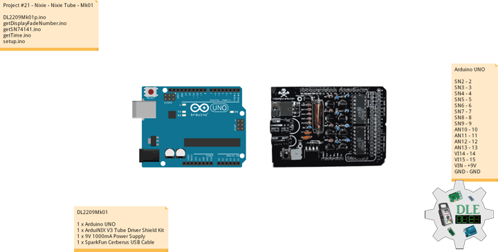
1 x Arduino UNO
1 x ArduiNIX V3 Tube Driver Shield Kit
1 x 9V 1000mA Power Supply
1 x SparkFun Cerberus USB Cable

Arduino UNO

SN2 – 2
SN3 – 3
SN4 – 4
SN5 – 5
SN6 – 6
SN7 – 7
SN8 – 8
SN9 – 9
AN10 – 10
AN11 – 11
AN12 – 12
AN13 – 13
VI14 – 14
VI15 – 15
VIN – +9V
GND – GND

DL2209Mk01p.ino

/* ***** Don Luc Electronics © *****
Software Version Information
Project #21 - Nixie - Nixie Tube - Mk01
21-01
DL2209Mk01p.ino
1 x Arduino UNO
1 x ArduiNIX V3 Tube Driver Shield Kit
1 x 9V 1000mA Power Supply
1 x SparkFun Cerberus USB Cable
*/

// Include the Library Code

// SN74141 (1)
int ledPin_0_a = 2;                
int ledPin_0_b = 3;
int ledPin_0_c = 4;
int ledPin_0_d = 5;

// SN74141 (2)
int ledPin_1_a = 6;                
int ledPin_1_b = 7;
int ledPin_1_c = 8;
int ledPin_1_d = 9;

// Anode pins
int ledPin_a_1 = 10;
int ledPin_a_2 = 11;
int ledPin_a_3 = 12;
int ledPin_a_4 = 13;

// NOTE: Grounding on virtual pins 14 and 15 
// (analog pins 0 and 1) will set the Hour and Mins.
int iVirtual14 = 14;
int iVirtual15 = 15;

// Fade
float fadeMax = 0.1f;
float fadeStep = 0.1f;
// Number Array
int NumberArray[8]={0,0,0,0,0,0,0,0};
int currNumberArray[8]={0,0,0,0,0,0,0,0};
float NumberArrayFadeInValue[8]={0.0f,0.0f,0.0f,0.0f,0.0f,0.0f,0.0f,0.0f};
float NumberArrayFadeOutValue[8]={5.0f,5.0f,5.0f,5.0f,5.0f,5.0f,5.0f,5.0f};

// Defines
// Sub seconds
long SSECS = 100;
// Milliseconds in a Sec
long SECS = 60;
// 60 Seconds in a Min.
long MINS = 60;
// 60 Mins in an hour
long HOURS = 60 * MINS;
// 24 Hours in a day. > Note: change the 24 to a 12 for non military time.
long DAYS = 12 * HOURS; 

// Time from when we started
long runTime = 0;

// Default time sets. clock will start at 12:34:00.
// This is so we can count the correct order of tubes.
long clockHourSet = 12;
long clockMinSet  = 34;
long clockSecSet  = 56;
long clockSSecSet  = 12;

int HourButtonPressed = false;
int MinButtonPressed = false;

// Software Version Information
String sver = "21-01";

void loop() {

  // Time
  isTime();
  
}

getDisplayFadeNumber.ino

// Display Fade Number
void DisplayFadeNumberString()
{
 
  // Anode channel 1 - numerals 0,4
  SetSN74141Chips(currNumberArray[0],currNumberArray[4]);   
  digitalWrite(ledPin_a_1, HIGH);   
  delay(NumberArrayFadeOutValue[0]);
  SetSN74141Chips(NumberArray[0],NumberArray[4]);   
  delay(NumberArrayFadeInValue[0]);
  digitalWrite(ledPin_a_1, LOW);
  
    // Anode channel 2 - numerals 1,5
  SetSN74141Chips(currNumberArray[1],currNumberArray[5]);   
  digitalWrite(ledPin_a_2, HIGH);   
  delay(NumberArrayFadeOutValue[1]);
  SetSN74141Chips(NumberArray[1],NumberArray[5]);   
  delay(NumberArrayFadeInValue[1]);
  digitalWrite(ledPin_a_2, LOW);
  
   // Anode channel 3 - numerals 2,6
  SetSN74141Chips(currNumberArray[2],currNumberArray[6]);   
  digitalWrite(ledPin_a_3, HIGH);   
  delay(NumberArrayFadeOutValue[2]);
  SetSN74141Chips(NumberArray[2],NumberArray[6]);   
  delay(NumberArrayFadeInValue[2]);
  digitalWrite(ledPin_a_3, LOW);
  
     // Anode channel 4 - numerals 3,7
  SetSN74141Chips(currNumberArray[3],currNumberArray[7]);   
  digitalWrite(ledPin_a_4, HIGH);   
  delay(NumberArrayFadeOutValue[3]);
  SetSN74141Chips(NumberArray[3],NumberArray[7]);   
  delay(NumberArrayFadeInValue[3]);
  digitalWrite(ledPin_a_4, LOW);
  
  // Loop thru and update all the arrays, and fades.
  for( int i = 0 ; i < 8 ; i ++ ) //equal to & of digits
  {
    if( NumberArray[i] != currNumberArray[i] )
    {
      NumberArrayFadeInValue[i] += fadeStep;
      NumberArrayFadeOutValue[i] -= fadeStep;
  
      if( NumberArrayFadeInValue[i] >= fadeMax )
      {
        NumberArrayFadeInValue[i] = 2.0f;
        NumberArrayFadeOutValue[i] = 4.0f; //affects the refresh cycle
        currNumberArray[i] = NumberArray[i];
      }
    }
  }
  
}

getSN74141.ino

// SN74141
// SN74141 : Truth Table
//D C B A #
//L,L,L,L 0
//L,L,L,H 1
//L,L,H,L 2
//L,L,H,H 3
//L,H,L,L 4
//L,H,L,H 5
//L,H,H,L 6
//L,H,H,H 7
//H,L,L,L 8
//H,L,L,H 9
// isSetupSN74141
void isSetupSN74141(){

  pinMode(ledPin_0_a, OUTPUT);      
  pinMode(ledPin_0_b, OUTPUT);      
  pinMode(ledPin_0_c, OUTPUT);      
  pinMode(ledPin_0_d, OUTPUT);    
  
  pinMode(ledPin_1_a, OUTPUT);      
  pinMode(ledPin_1_b, OUTPUT);      
  pinMode(ledPin_1_c, OUTPUT);      
  pinMode(ledPin_1_d, OUTPUT);      
  
  pinMode(ledPin_a_1, OUTPUT);      
  pinMode(ledPin_a_2, OUTPUT);      
  pinMode(ledPin_a_3, OUTPUT);   
  pinMode(ledPin_a_4, OUTPUT);    
 
  // NOTE: Grounding on virtual pins 14 and 15 
  // (analog pins 0 and 1) will set the Hour and Mins.
  // Set the vertual pin 14 (pin 0 on the analog inputs )
  pinMode( iVirtual14, INPUT );
  // Set pin 14 as a pull up resistor.
  digitalWrite(iVirtual14, HIGH);
  // Set the vertual pin 15 (pin 1 on the analog inputs )
  pinMode( iVirtual15, INPUT );
  // Set pin 15 as a pull up resistor.
  digitalWrite(iVirtual15, HIGH);
  
}
// SetSN74141Chips
void SetSN74141Chips( int num2, int num1 )
{
  
  // Set defaults
  // Will display a zero.
  int a = 0;
  int b = 0;
  int c = 0;
  int d = 0;
  
  // Load the a,b,c,d.. to send to the SN74141 IC (1)
  switch( num1 )
  {
    case 0:
      a=0;
      b=0;
      c=0;
      d=0;
      break;
    case 1:
      a=1;
      b=0;
      c=0;
      d=0;
      break;
    case 2:
      a=0;
      b=1;
      c=0;
      d=0;
      break;
    case 3:
      a=1;
      b=1;
      c=0;
      d=0;
      break;
    case 4:
      a=0;
      b=0;
      c=1;
      d=0;
      break;
    case 5:
      a=1;
      b=0;
      c=1;
      d=0;
      break;
    case 6: 
      a=0;
      b=1;
      c=1;
      d=0;
      break;
    case 7:
      a=1;
      b=1;
      c=1;
      d=0;
      break;
    case 8:
      a=0;
      b=0;
      c=0;
      d=1;
      break;
    case 9:
      a=1;
      b=0;
      c=0;
      d=1;
      break;
    default:
      a=1;
      b=1;
      c=1;
      d=1;
      break;
  }  
  
  // Write to output pins.
  digitalWrite(ledPin_0_d, d);
  digitalWrite(ledPin_0_c, c);
  digitalWrite(ledPin_0_b, b);
  digitalWrite(ledPin_0_a, a);

  // Load the a,b,c,d.. to send to the SN74141 IC (2)
  switch( num2 )
  {
    case 0:
      a=0;
      b=0;
      c=0;
      d=0;
      break;
    case 1:
      a=1;
      b=0;
      c=0;
      d=0;
      break;
    case 2:
      a=0;
      b=1;
      c=0;
      d=0;
      break;
    case 3:
      a=1;
      b=1;
      c=0;
      d=0;
      break;
    case 4:
      a=0;
      b=0;
      c=1;
      d=0;
      break;
    case 5:
      a=1;
      b=0;
      c=1;
      d=0;
      break;
    case 6:
      a=0;
      b=1;
      c=1;
      d=0;
      break;
    case 7:
      a=1;
      b=1;
      c=1;
      d=0;
      break;
    case 8:
      a=0;
      b=0;
      c=0;
      d=1;
      break;
    case 9:
      a=1;
      b=0;
      c=0;
      d=1;
      break;
    default:
      a=1;
      b=1;
      c=1;
      d=1;
      break;
  }
  
  // Write to output pins
  digitalWrite(ledPin_1_d, d);
  digitalWrite(ledPin_1_c, c);
  digitalWrite(ledPin_1_b, b);
  digitalWrite(ledPin_1_a, a);
  
}

getTime.ino

// Time
void isTime(){

  // Get milliseconds.
  runTime = millis();
  //int ssTime = millis();
  
  int hourInput = digitalRead(iVirtual14);  
  int minInput  = digitalRead(iVirtual15);

  if( hourInput == 0 )
    HourButtonPressed = true;
  if( minInput == 0 )
    MinButtonPressed = true;
  if( HourButtonPressed == true && hourInput == 1 )
  {
    clockHourSet++;
    HourButtonPressed = false;
  }
  if( MinButtonPressed == true && minInput == 1 )
  {
    clockMinSet++;
    MinButtonPressed = false;
  }

  // Get time in seconds.
  // Change this value to speed up or
  // slow down the clock, set to smaller number such as 10, 1, or 100 for debugging
  long time = (runTime) / 1000;
  int sstime = (runTime) / 10;
  // Set time based on offset..
  // long hbump = 60*60*clockHourSet;
  //long sbump = 60*60*60*clockHourSet; //change hourset to secondset
  long hbump = 60*60*clockHourSet;
  long mbump = 60*clockMinSet;
  time += mbump + hbump;

  // Convert time to days,hours,mins,seconds
  long days  = time / DAYS;    time -= days  * DAYS; 
  long hours = time / HOURS;   time -= hours * HOURS; 
  long minutes  = time / MINS;    time -= minutes  * MINS; 
  long seconds  = time;      
//  long sseconds  = 76;// time -= seconds  * SECS;
  long sseconds  = runTime / SECS; time -= sseconds  * SECS; 

  // Get the high and low order values for hours,min,seconds. 
  int lowerHours = hours % 10;
  int upperHours = hours - lowerHours;
  int lowerMins = minutes % 10;
  int upperMins = minutes - lowerMins;
  int lowerSeconds = seconds % 10;
  int upperSeconds = seconds - lowerSeconds;
  int lowerSSeconds = sseconds % 10;
  //- lowerSSeconds;
  int upperSSeconds = lowerSSeconds % 10; upperSSeconds = upperSSeconds /10;
  
  if( upperSSeconds >= 10 )  upperSSeconds = upperSSeconds / 10;
  if( upperSeconds >= 10 )   upperSeconds = upperSeconds / 10;
  if( upperMins >= 10 )      upperMins = upperMins / 10;
  if( upperHours >= 10 )     upperHours = upperHours / 10;
 
  if( upperHours == 0 && lowerHours == 0 )
  {
    upperHours = 1;
    lowerHours = 2;
  }
  
  // Fill in the Number array used to display on the tubes.
  
  NumberArray[7] = upperHours;
  NumberArray[6] = lowerHours;
  NumberArray[5] = upperMins;
  NumberArray[4] = lowerMins;
  NumberArray[3] = upperSeconds;  
  NumberArray[2] = lowerSeconds;
  NumberArray[1] = lowerSSeconds; //upperSSeconds;  
  NumberArray[0] = lowerSSeconds; //lowerSSeconds;
  
  Serial.print(lowerSSeconds);
  Serial.println();
  // Display.
  //DisplayFadeNumberString();
  // Display.
  DisplayFadeNumberString();
  
}

setup.ino

// Setup
void setup() {

  // isSetupSN74141
  isSetupSN74141();

  // Open serial communications
 Serial.begin(9600);

}

——

People can contact us: https://www.donluc.com/?page_id=1927

Technology Experience

  • Single-Board Microcontrollers (PIC, Arduino, Raspberry Pi,Espressif, etc…)
  • IoT
  • Robotics
  • Camera and Video Capture Receiver Stationary, Wheel/Tank and Underwater Vehicle
  • Unmanned Vehicles Terrestrial and Marine
  • Research & Development (R & D)

Instructor and E-Mentor

  • IoT
  • PIC Microcontrollers
  • Arduino
  • Raspberry Pi
  • Espressif
  • Robotics

Follow Us

J. Luc Paquin – Curriculum Vitae – 2022 English & Español
https://www.jlpconsultants.com/luc/

Web: https://www.donluc.com/
Web: https://www.jlpconsultants.com/
Facebook: https://www.facebook.com/neosteam.labs.9/
YouTube: https://www.youtube.com/channel/UC5eRjrGn1CqkkGfZy0jxEdA
Twitter: https://twitter.com/labs_steam
Pinterest: https://www.pinterest.com/NeoSteamLabs/
Instagram: https://www.instagram.com/neosteamlabs/

Don Luc
Categories
Archives