
——
#DonLucElectronics #DonLuc #NixieTube #Nixie #ArduiNIX #ArduinoUNO #Arduino #Project #Fritzing #Programming #Electronics #Microcontrollers #Consultant
——
——
——
——
——
ArduiNIX
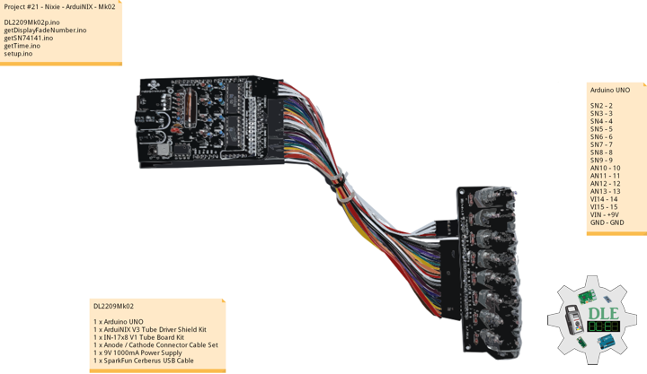
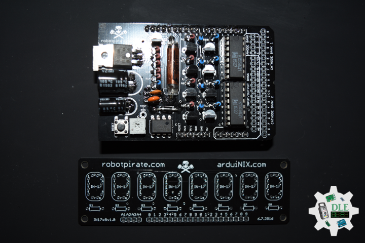
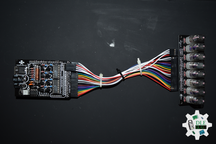
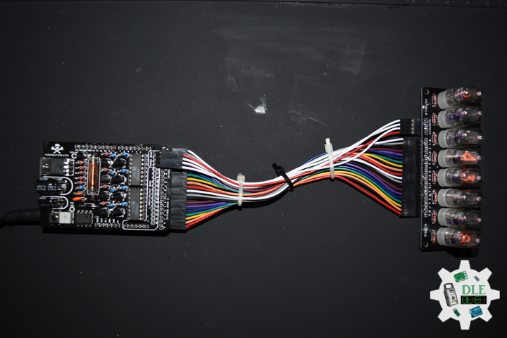
The ArduiNIX is an Arduino compatible shield which plugs right onto the top of the Arduino UNO board. ArduiNIX takes care of stepping power from 9 VDC wall adapter power supply up to a maximum of approximately 250 VDC to drive any and all Nixie tubes. ArduiNIX also provides Multiplexed display for up to 80 elements by using 4 anode channels and 20 cathode channels. Multiplexing increases the life expectancy of your Nixie tube investment.
Not only does the ArduiNIX provide a Nixie tube platform for standard clock functions, but it is also user programmable, meaning if you can program it using the arduino environment, you can make it happen on your Nixie display. Take special care when working with the ArduiNIX. The ArduiNIX Shield operates at high voltages. Be careful when handling it while it’s powered up. Normally the Arduino is safe to handle, but when used in conjunction with the ArduiNIX, voltages in excess of 200 volts may be achieved. Use caution. An IN-17 x 8 display board, and 8 x Russian IN-17 Nixie tubes.
DL2209Mk02
1 x Arduino UNO
1 x ArduiNIX V3 Tube Driver Shield Kit
1 x IN-17×8 V1 Tube Board Kit
1 x Anode / Cathode Connector Cable Set
1 x 9V 1000mA Power Supply
1 x SparkFun Cerberus USB Cable
Arduino UNO
SN2 – 2
SN3 – 3
SN4 – 4
SN5 – 5
SN6 – 6
SN7 – 7
SN8 – 8
SN9 – 9
AN10 – 10
AN11 – 11
AN12 – 12
AN13 – 13
VI14 – 14
VI15 – 15
VIN – +9V
GND – GND
DL2209Mk02p.ino
/* ***** Don Luc Electronics © *****
Software Version Information
Project #21 - Nixie - ArduiNIX - Mk02
21-02
DL2209Mk02p.ino
1 x Arduino UNO
1 x ArduiNIX V3 Tube Driver Shield Kit
1 x IN-17x8 V1 Tube Board Kit
1 x Anode / Cathode Connector Cable Set
1 x 9V 1000mA Power Supply
1 x SparkFun Cerberus USB Cable
*/

// Include the Library Code

// SN74141 (1)
int ledPin_0_a = 2;
int ledPin_0_b = 3;
int ledPin_0_c = 4;
int ledPin_0_d = 5;

// SN74141 (2)
int ledPin_1_a = 6;
int ledPin_1_b = 7;
int ledPin_1_c = 8;
int ledPin_1_d = 9;

// Anode pins
int ledPin_a_1 = 10;
int ledPin_a_2 = 11;
int ledPin_a_3 = 12;
int ledPin_a_4 = 13;

// NOTE: Grounding on virtual pins 14 and 15
// (analog pins 0 and 1) will set the Hour and Mins.
int iVirtual14 = 14;
int iVirtual15 = 15;

// Fade
float fadeMax = 0.1f;
float fadeStep = 0.1f;
// Number Array
int NumberArray[8]={0,0,0,0,0,0,0,0};
int currNumberArray[8]={0,0,0,0,0,0,0,0};
float NumberArrayFadeInValue[8]={0.0f,0.0f,0.0f,0.0f,0.0f,0.0f,0.0f,0.0f};
float NumberArrayFadeOutValue[8]={5.0f,5.0f,5.0f,5.0f,5.0f,5.0f,5.0f,5.0f};

// Defines
// Sub seconds
long SSECS = 100;
// Milliseconds in a Sec
long SECS = 60;
// 60 Seconds in a Min.
long MINS = 60;
// 60 Mins in an hour
long HOURS = 60 * MINS;
// 24 Hours in a day. > Note: change the 24 to a 12 for non military time.
long DAYS = 12 * HOURS;

// Time from when we started
long runTime = 0;

// Default time sets. clock will start at 12:34:00.
// This is so we can count the correct order of tubes.
long clockHourSet;
long clockMinSet;
long clockSecSet;
//long clockSSecSet;

int HourButtonPressed = false;
int MinButtonPressed = false;

// Software Version Information
String sver = "21-02";

void loop() {

  // Time
  isTime();

}
getDisplayFadeNumber.ino
// Display Fade Number
void DisplayFadeNumberString()
{

  // Anode channel 1 - numerals 0,4
  SetSN74141Chips(currNumberArray[0],currNumberArray[4]);
  digitalWrite(ledPin_a_1, HIGH);
  delay(NumberArrayFadeOutValue[0]);
  SetSN74141Chips(NumberArray[0],NumberArray[4]);
  delay(NumberArrayFadeInValue[0]);
  digitalWrite(ledPin_a_1, LOW);

    // Anode channel 2 - numerals 1,5
  SetSN74141Chips(currNumberArray[1],currNumberArray[5]);
  digitalWrite(ledPin_a_2, HIGH);
  delay(NumberArrayFadeOutValue[1]);
  SetSN74141Chips(NumberArray[1],NumberArray[5]);
  delay(NumberArrayFadeInValue[1]);
  digitalWrite(ledPin_a_2, LOW);

   // Anode channel 3 - numerals 2,6
  SetSN74141Chips(currNumberArray[2],currNumberArray[6]);
  digitalWrite(ledPin_a_3, HIGH);
  delay(NumberArrayFadeOutValue[2]);
  SetSN74141Chips(NumberArray[2],NumberArray[6]);
  delay(NumberArrayFadeInValue[2]);
  digitalWrite(ledPin_a_3, LOW);

     // Anode channel 4 - numerals 3,7
  SetSN74141Chips(currNumberArray[3],currNumberArray[7]);
  digitalWrite(ledPin_a_4, HIGH);
  delay(NumberArrayFadeOutValue[3]);
  SetSN74141Chips(NumberArray[3],NumberArray[7]);
  delay(NumberArrayFadeInValue[3]);
  digitalWrite(ledPin_a_4, LOW);

  // Loop thru and update all the arrays, and fades.
  for( int i = 0 ; i < 8 ; i ++ ) //equal to & of digits
  {
    if( NumberArray[i] != currNumberArray[i] )
    {
      NumberArrayFadeInValue[i] += fadeStep;
      NumberArrayFadeOutValue[i] -= fadeStep;

      if( NumberArrayFadeInValue[i] >= fadeMax )
      {
        NumberArrayFadeInValue[i] = 2.0f;
        NumberArrayFadeOutValue[i] = 4.0f; //affects the refresh cycle
        currNumberArray[i] = NumberArray[i];
      }
    }
  }

}
getSN74141.ino
// SN74141
// SN74141 : Truth Table
//D C B A #
//L,L,L,L 0
//L,L,L,H 1
//L,L,H,L 2
//L,L,H,H 3
//L,H,L,L 4
//L,H,L,H 5
//L,H,H,L 6
//L,H,H,H 7
//H,L,L,L 8
//H,L,L,H 9
// isSetupSN74141
void isSetupSN74141(){

  pinMode(ledPin_0_a, OUTPUT);
  pinMode(ledPin_0_b, OUTPUT);
  pinMode(ledPin_0_c, OUTPUT);
  pinMode(ledPin_0_d, OUTPUT);

  pinMode(ledPin_1_a, OUTPUT);
  pinMode(ledPin_1_b, OUTPUT);
  pinMode(ledPin_1_c, OUTPUT);
  pinMode(ledPin_1_d, OUTPUT);

  pinMode(ledPin_a_1, OUTPUT);
  pinMode(ledPin_a_2, OUTPUT);
  pinMode(ledPin_a_3, OUTPUT);
  pinMode(ledPin_a_4, OUTPUT);

  // NOTE: Grounding on virtual pins 14 and 15
  // (analog pins 0 and 1) will set the Hour and Mins.
  // Set the vertual pin 14 (pin 0 on the analog inputs )
  pinMode( iVirtual14, INPUT );
  // Set pin 14 as a pull up resistor.
  digitalWrite(iVirtual14, HIGH);
  // Set the vertual pin 15 (pin 1 on the analog inputs )
  pinMode( iVirtual15, INPUT );
  // Set pin 15 as a pull up resistor.
  digitalWrite(iVirtual15, HIGH);

}
// SetSN74141Chips
void SetSN74141Chips( int num2, int num1 )
{

  // Set defaults
  // Will display a zero.
  int a = 0;
  int b = 0;
  int c = 0;
  int d = 0;

  // Load the a,b,c,d.. to send to the SN74141 IC (1)
  switch( num1 )
  {
    case 0:
      a=0;
      b=0;
      c=0;
      d=0;
      break;
    case 1:
      a=1;
      b=0;
      c=0;
      d=0;
      break;
    case 2:
      a=0;
      b=1;
      c=0;
      d=0;
      break;
    case 3:
      a=1;
      b=1;
      c=0;
      d=0;
      break;
    case 4:
      a=0;
      b=0;
      c=1;
      d=0;
      break;
    case 5:
      a=1;
      b=0;
      c=1;
      d=0;
      break;
    case 6:
      a=0;
      b=1;
      c=1;
      d=0;
      break;
    case 7:
      a=1;
      b=1;
      c=1;
      d=0;
      break;
    case 8:
      a=0;
      b=0;
      c=0;
      d=1;
      break;
    case 9:
      a=1;
      b=0;
      c=0;
      d=1;
      break;
    default:
      a=1;
      b=1;
      c=1;
      d=1;
      break;
  }

  // Write to output pins.
  digitalWrite(ledPin_0_d, d);
  digitalWrite(ledPin_0_c, c);
  digitalWrite(ledPin_0_b, b);
  digitalWrite(ledPin_0_a, a);

  // Load the a,b,c,d.. to send to the SN74141 IC (2)
  switch( num2 )
  {
    case 0:
      a=0;
      b=0;
      c=0;
      d=0;
      break;
    case 1:
      a=1;
      b=0;
      c=0;
      d=0;
      break;
    case 2:
      a=0;
      b=1;
      c=0;
      d=0;
      break;
    case 3:
      a=1;
      b=1;
      c=0;
      d=0;
      break;
    case 4:
      a=0;
      b=0;
      c=1;
      d=0;
      break;
    case 5:
      a=1;
      b=0;
      c=1;
      d=0;
      break;
    case 6:
      a=0;
      b=1;
      c=1;
      d=0;
      break;
    case 7:
      a=1;
      b=1;
      c=1;
      d=0;
      break;
    case 8:
      a=0;
      b=0;
      c=0;
      d=1;
      break;
    case 9:
      a=1;
      b=0;
      c=0;
      d=1;
      break;
    default:
      a=1;
      b=1;
      c=1;
      d=1;
      break;
  }

  // Write to output pins
  digitalWrite(ledPin_1_d, d);
  digitalWrite(ledPin_1_c, c);
  digitalWrite(ledPin_1_b, b);
  digitalWrite(ledPin_1_a, a);

}
getTime.ino
// Time
void isTime(){

  // Get milliseconds.
  runTime = millis();
  //int ssTime = millis();

  int hourInput = digitalRead(iVirtual14);
  int minInput  = digitalRead(iVirtual15);

  if( hourInput == 0 )
    HourButtonPressed = true;
  if( minInput == 0 )
    MinButtonPressed = true;
  if( HourButtonPressed == true && hourInput == 1 )
  {
    clockHourSet++;
    HourButtonPressed = false;
  }
  if( MinButtonPressed == true && minInput == 1 )
  {
    clockMinSet++;
    MinButtonPressed = false;
  }

  // Get time in seconds.
  // Change this value to speed up or
  // slow down the clock, set to smaller number such as 10, 1, or 100 for debugging
  long time = (runTime) / 1000;
  int sstime = (runTime) / 10;
  // Set time based on offset..
  // long hbump = 60*60*clockHourSet;
  //long sbump = 60*60*60*clockHourSet; //change hourset to secondset
  long hbump = 60*60*clockHourSet;
  long mbump = 60*clockMinSet;
  time += mbump + hbump;

  // Convert time to days,hours,mins,seconds
  long days  = time / DAYS;    time -= days  * DAYS;
  long hours = time / HOURS;   time -= hours * HOURS;
  long minutes  = time / MINS;    time -= minutes  * MINS;
  long seconds  = time;
//  long sseconds  = 76;// time -= seconds  * SECS;
  long sseconds  = runTime / SECS; time -= sseconds  * SECS;

  // Get the high and low order values for hours,min,seconds.
  int lowerHours = hours % 10;
  int upperHours = hours - lowerHours;
  int lowerMins = minutes % 10;
  int upperMins = minutes - lowerMins;
  int lowerSeconds = seconds % 10;
  int upperSeconds = seconds - lowerSeconds;
  int lowerSSeconds = sseconds % 10;
  //- lowerSSeconds;
  int upperSSeconds = lowerSSeconds % 10; upperSSeconds = upperSSeconds /10;

  if( upperSSeconds >= 10 )  upperSSeconds = upperSSeconds / 10;
  if( upperSeconds >= 10 )   upperSeconds = upperSeconds / 10;
  if( upperMins >= 10 )      upperMins = upperMins / 10;
  if( upperHours >= 10 )     upperHours = upperHours / 10;

  if( upperHours == 0 && lowerHours == 0 )
  {
    upperHours = 1;
    lowerHours = 2;
  }

  // Fill in the Number array used to display on the tubes.

  NumberArray[7] = upperHours;
  NumberArray[6] = lowerHours;
  NumberArray[5] = upperMins;
  NumberArray[4] = lowerMins;
  NumberArray[3] = upperSeconds;
  NumberArray[2] = lowerSeconds;
  NumberArray[1] = lowerSSeconds; //upperSSeconds;
  NumberArray[0] = lowerSSeconds; //lowerSSeconds;

  Serial.print(lowerSSeconds);
  Serial.println();
  // Display.
  //DisplayFadeNumberString();
  // Display.
  DisplayFadeNumberString();

}
setup.ino
// Setup
void setup() {

  // isSetupSN74141
  isSetupSN74141();

  // Open serial communications
 Serial.begin(9600);

}
——
People can contact us: https://www.donluc.com/?page_id=1927
Technology Experience
- Single-Board Microcontrollers (PIC, Arduino, Raspberry Pi,Espressif, etc…)
- IoT
- Robotics
- Camera and Video Capture Receiver Stationary, Wheel/Tank and Underwater Vehicle
- Unmanned Vehicles Terrestrial and Marine
- Research & Development (R & D)
Instructor and E-Mentor
- IoT
- PIC Microcontrollers
- Arduino
- Raspberry Pi
- Espressif
- Robotics
Follow Us
J. Luc Paquin – Curriculum Vitae – 2022 English & Español
https://www.jlpconsultants.com/luc/
Web: https://www.donluc.com/
Web: https://www.jlpconsultants.com/
Facebook: https://www.facebook.com/neosteam.labs.9/
YouTube: https://www.youtube.com/channel/UC5eRjrGn1CqkkGfZy0jxEdA
Twitter: https://twitter.com/labs_steam
Pinterest: https://www.pinterest.com/NeoSteamLabs/
Instagram: https://www.instagram.com/neosteamlabs/
Don Luc