
——
#DonLucElectronics #DonLuc #NixieTube #Nixie #ArduiNIX #ArduinoUNO #Arduino #Project #Fritzing #Programming #Electronics #Microcontrollers #Consultant
——
——
——
——
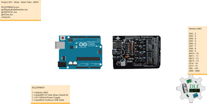
Nixie Tube
A Nixie tube, or cold cathode display, is an electronic device used for displaying numerals or other information using glow discharge. The glass tube contains a wire-mesh anode and multiple cathodes, shaped like numerals or other symbols. Applying power to one cathode surrounds it with an orange glow discharge. The tube is filled with a gas at low pressure.
The early Nixie displays were made by a small vacuum tube manufacturer called Haydu Brothers Laboratories, and introduced in 1955 by Burroughs Corporation, who purchased Haydu. The name Nixie was derived by Burroughs from “NIX I”, an abbreviation of “Numeric Indicator eXperimental No. 1”, although this may have been a backronym designed to justify the evocation of the mythical creature with this name.
Citing dissatisfaction with the aesthetics of modern digital displays and a nostalgic fondness for the styling of obsolete technology, significant numbers of electronics enthusiasts have shown interest in reviving Nixies.
DL2209Mk01
1 x Arduino UNO
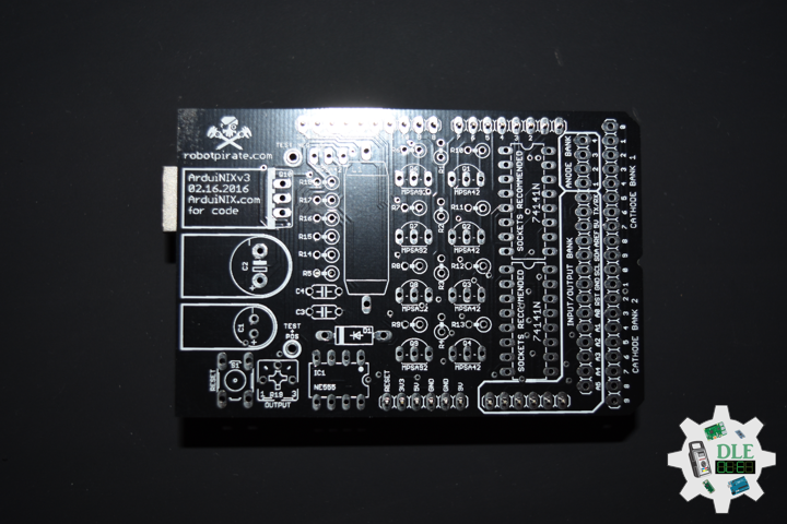
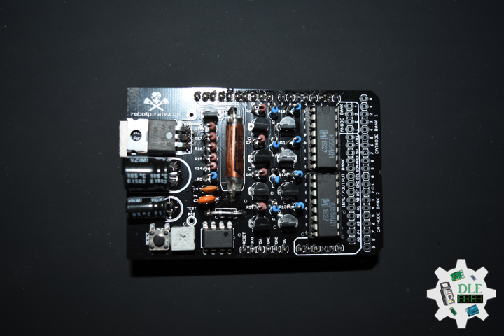
1 x ArduiNIX V3 Tube Driver Shield Kit
1 x 9V 1000mA Power Supply
1 x SparkFun Cerberus USB Cable
Arduino UNO
SN2 – 2
SN3 – 3
SN4 – 4
SN5 – 5
SN6 – 6
SN7 – 7
SN8 – 8
SN9 – 9
AN10 – 10
AN11 – 11
AN12 – 12
AN13 – 13
VI14 – 14
VI15 – 15
VIN – +9V
GND – GND
DL2209Mk01p.ino
/* ***** Don Luc Electronics © *****
Software Version Information
Project #21 - Nixie - Nixie Tube - Mk01
21-01
DL2209Mk01p.ino
1 x Arduino UNO
1 x ArduiNIX V3 Tube Driver Shield Kit
1 x 9V 1000mA Power Supply
1 x SparkFun Cerberus USB Cable
*/

// Include the Library Code

// SN74141 (1)
int ledPin_0_a = 2;
int ledPin_0_b = 3;
int ledPin_0_c = 4;
int ledPin_0_d = 5;

// SN74141 (2)
int ledPin_1_a = 6;
int ledPin_1_b = 7;
int ledPin_1_c = 8;
int ledPin_1_d = 9;

// Anode pins
int ledPin_a_1 = 10;
int ledPin_a_2 = 11;
int ledPin_a_3 = 12;
int ledPin_a_4 = 13;

// NOTE: Grounding on virtual pins 14 and 15
// (analog pins 0 and 1) will set the Hour and Mins.
int iVirtual14 = 14;
int iVirtual15 = 15;

// Fade
float fadeMax = 0.1f;
float fadeStep = 0.1f;
// Number Array
int NumberArray[8]={0,0,0,0,0,0,0,0};
int currNumberArray[8]={0,0,0,0,0,0,0,0};
float NumberArrayFadeInValue[8]={0.0f,0.0f,0.0f,0.0f,0.0f,0.0f,0.0f,0.0f};
float NumberArrayFadeOutValue[8]={5.0f,5.0f,5.0f,5.0f,5.0f,5.0f,5.0f,5.0f};

// Defines
// Sub seconds
long SSECS = 100;
// Milliseconds in a Sec
long SECS = 60;
// 60 Seconds in a Min.
long MINS = 60;
// 60 Mins in an hour
long HOURS = 60 * MINS;
// 24 Hours in a day. > Note: change the 24 to a 12 for non military time.
long DAYS = 12 * HOURS;

// Time from when we started
long runTime = 0;

// Default time sets. clock will start at 12:34:00.
// This is so we can count the correct order of tubes.
long clockHourSet = 12;
long clockMinSet  = 34;
long clockSecSet  = 56;
long clockSSecSet  = 12;

int HourButtonPressed = false;
int MinButtonPressed = false;

// Software Version Information
String sver = "21-01";

void loop() {

  // Time
  isTime();

}
getDisplayFadeNumber.ino
// Display Fade Number
void DisplayFadeNumberString()
{

  // Anode channel 1 - numerals 0,4
  SetSN74141Chips(currNumberArray[0],currNumberArray[4]);
  digitalWrite(ledPin_a_1, HIGH);
  delay(NumberArrayFadeOutValue[0]);
  SetSN74141Chips(NumberArray[0],NumberArray[4]);
  delay(NumberArrayFadeInValue[0]);
  digitalWrite(ledPin_a_1, LOW);

    // Anode channel 2 - numerals 1,5
  SetSN74141Chips(currNumberArray[1],currNumberArray[5]);
  digitalWrite(ledPin_a_2, HIGH);
  delay(NumberArrayFadeOutValue[1]);
  SetSN74141Chips(NumberArray[1],NumberArray[5]);
  delay(NumberArrayFadeInValue[1]);
  digitalWrite(ledPin_a_2, LOW);

   // Anode channel 3 - numerals 2,6
  SetSN74141Chips(currNumberArray[2],currNumberArray[6]);
  digitalWrite(ledPin_a_3, HIGH);
  delay(NumberArrayFadeOutValue[2]);
  SetSN74141Chips(NumberArray[2],NumberArray[6]);
  delay(NumberArrayFadeInValue[2]);
  digitalWrite(ledPin_a_3, LOW);

     // Anode channel 4 - numerals 3,7
  SetSN74141Chips(currNumberArray[3],currNumberArray[7]);
  digitalWrite(ledPin_a_4, HIGH);
  delay(NumberArrayFadeOutValue[3]);
  SetSN74141Chips(NumberArray[3],NumberArray[7]);
  delay(NumberArrayFadeInValue[3]);
  digitalWrite(ledPin_a_4, LOW);

  // Loop thru and update all the arrays, and fades.
  for( int i = 0 ; i < 8 ; i ++ ) //equal to & of digits
  {
    if( NumberArray[i] != currNumberArray[i] )
    {
      NumberArrayFadeInValue[i] += fadeStep;
      NumberArrayFadeOutValue[i] -= fadeStep;

      if( NumberArrayFadeInValue[i] >= fadeMax )
      {
        NumberArrayFadeInValue[i] = 2.0f;
        NumberArrayFadeOutValue[i] = 4.0f; //affects the refresh cycle
        currNumberArray[i] = NumberArray[i];
      }
    }
  }

}
getSN74141.ino
// SN74141
// SN74141 : Truth Table
//D C B A #
//L,L,L,L 0
//L,L,L,H 1
//L,L,H,L 2
//L,L,H,H 3
//L,H,L,L 4
//L,H,L,H 5
//L,H,H,L 6
//L,H,H,H 7
//H,L,L,L 8
//H,L,L,H 9
// isSetupSN74141
void isSetupSN74141(){

  pinMode(ledPin_0_a, OUTPUT);
  pinMode(ledPin_0_b, OUTPUT);
  pinMode(ledPin_0_c, OUTPUT);
  pinMode(ledPin_0_d, OUTPUT);

  pinMode(ledPin_1_a, OUTPUT);
  pinMode(ledPin_1_b, OUTPUT);
  pinMode(ledPin_1_c, OUTPUT);
  pinMode(ledPin_1_d, OUTPUT);

  pinMode(ledPin_a_1, OUTPUT);
  pinMode(ledPin_a_2, OUTPUT);
  pinMode(ledPin_a_3, OUTPUT);
  pinMode(ledPin_a_4, OUTPUT);

  // NOTE: Grounding on virtual pins 14 and 15
  // (analog pins 0 and 1) will set the Hour and Mins.
  // Set the vertual pin 14 (pin 0 on the analog inputs )
  pinMode( iVirtual14, INPUT );
  // Set pin 14 as a pull up resistor.
  digitalWrite(iVirtual14, HIGH);
  // Set the vertual pin 15 (pin 1 on the analog inputs )
  pinMode( iVirtual15, INPUT );
  // Set pin 15 as a pull up resistor.
  digitalWrite(iVirtual15, HIGH);

}
// SetSN74141Chips
void SetSN74141Chips( int num2, int num1 )
{

  // Set defaults
  // Will display a zero.
  int a = 0;
  int b = 0;
  int c = 0;
  int d = 0;

  // Load the a,b,c,d.. to send to the SN74141 IC (1)
  switch( num1 )
  {
    case 0:
      a=0;
      b=0;
      c=0;
      d=0;
      break;
    case 1:
      a=1;
      b=0;
      c=0;
      d=0;
      break;
    case 2:
      a=0;
      b=1;
      c=0;
      d=0;
      break;
    case 3:
      a=1;
      b=1;
      c=0;
      d=0;
      break;
    case 4:
      a=0;
      b=0;
      c=1;
      d=0;
      break;
    case 5:
      a=1;
      b=0;
      c=1;
      d=0;
      break;
    case 6:
      a=0;
      b=1;
      c=1;
      d=0;
      break;
    case 7:
      a=1;
      b=1;
      c=1;
      d=0;
      break;
    case 8:
      a=0;
      b=0;
      c=0;
      d=1;
      break;
    case 9:
      a=1;
      b=0;
      c=0;
      d=1;
      break;
    default:
      a=1;
      b=1;
      c=1;
      d=1;
      break;
  }

  // Write to output pins.
  digitalWrite(ledPin_0_d, d);
  digitalWrite(ledPin_0_c, c);
  digitalWrite(ledPin_0_b, b);
  digitalWrite(ledPin_0_a, a);

  // Load the a,b,c,d.. to send to the SN74141 IC (2)
  switch( num2 )
  {
    case 0:
      a=0;
      b=0;
      c=0;
      d=0;
      break;
    case 1:
      a=1;
      b=0;
      c=0;
      d=0;
      break;
    case 2:
      a=0;
      b=1;
      c=0;
      d=0;
      break;
    case 3:
      a=1;
      b=1;
      c=0;
      d=0;
      break;
    case 4:
      a=0;
      b=0;
      c=1;
      d=0;
      break;
    case 5:
      a=1;
      b=0;
      c=1;
      d=0;
      break;
    case 6:
      a=0;
      b=1;
      c=1;
      d=0;
      break;
    case 7:
      a=1;
      b=1;
      c=1;
      d=0;
      break;
    case 8:
      a=0;
      b=0;
      c=0;
      d=1;
      break;
    case 9:
      a=1;
      b=0;
      c=0;
      d=1;
      break;
    default:
      a=1;
      b=1;
      c=1;
      d=1;
      break;
  }

  // Write to output pins
  digitalWrite(ledPin_1_d, d);
  digitalWrite(ledPin_1_c, c);
  digitalWrite(ledPin_1_b, b);
  digitalWrite(ledPin_1_a, a);

}
getTime.ino
// Time
void isTime(){

  // Get milliseconds.
  runTime = millis();
  //int ssTime = millis();

  int hourInput = digitalRead(iVirtual14);
  int minInput  = digitalRead(iVirtual15);

  if( hourInput == 0 )
    HourButtonPressed = true;
  if( minInput == 0 )
    MinButtonPressed = true;
  if( HourButtonPressed == true && hourInput == 1 )
  {
    clockHourSet++;
    HourButtonPressed = false;
  }
  if( MinButtonPressed == true && minInput == 1 )
  {
    clockMinSet++;
    MinButtonPressed = false;
  }

  // Get time in seconds.
  // Change this value to speed up or
  // slow down the clock, set to smaller number such as 10, 1, or 100 for debugging
  long time = (runTime) / 1000;
  int sstime = (runTime) / 10;
  // Set time based on offset..
  // long hbump = 60*60*clockHourSet;
  //long sbump = 60*60*60*clockHourSet; //change hourset to secondset
  long hbump = 60*60*clockHourSet;
  long mbump = 60*clockMinSet;
  time += mbump + hbump;

  // Convert time to days,hours,mins,seconds
  long days  = time / DAYS;    time -= days  * DAYS;
  long hours = time / HOURS;   time -= hours * HOURS;
  long minutes  = time / MINS;    time -= minutes  * MINS;
  long seconds  = time;
//  long sseconds  = 76;// time -= seconds  * SECS;
  long sseconds  = runTime / SECS; time -= sseconds  * SECS;

  // Get the high and low order values for hours,min,seconds.
  int lowerHours = hours % 10;
  int upperHours = hours - lowerHours;
  int lowerMins = minutes % 10;
  int upperMins = minutes - lowerMins;
  int lowerSeconds = seconds % 10;
  int upperSeconds = seconds - lowerSeconds;
  int lowerSSeconds = sseconds % 10;
  //- lowerSSeconds;
  int upperSSeconds = lowerSSeconds % 10; upperSSeconds = upperSSeconds /10;

  if( upperSSeconds >= 10 )  upperSSeconds = upperSSeconds / 10;
  if( upperSeconds >= 10 )   upperSeconds = upperSeconds / 10;
  if( upperMins >= 10 )      upperMins = upperMins / 10;
  if( upperHours >= 10 )     upperHours = upperHours / 10;

  if( upperHours == 0 && lowerHours == 0 )
  {
    upperHours = 1;
    lowerHours = 2;
  }

  // Fill in the Number array used to display on the tubes.

  NumberArray[7] = upperHours;
  NumberArray[6] = lowerHours;
  NumberArray[5] = upperMins;
  NumberArray[4] = lowerMins;
  NumberArray[3] = upperSeconds;
  NumberArray[2] = lowerSeconds;
  NumberArray[1] = lowerSSeconds; //upperSSeconds;
  NumberArray[0] = lowerSSeconds; //lowerSSeconds;

  Serial.print(lowerSSeconds);
  Serial.println();
  // Display.
  //DisplayFadeNumberString();
  // Display.
  DisplayFadeNumberString();

}
setup.ino
// Setup
void setup() {

  // isSetupSN74141
  isSetupSN74141();

  // Open serial communications
 Serial.begin(9600);

}
——
People can contact us: https://www.donluc.com/?page_id=1927
Technology Experience
- Single-Board Microcontrollers (PIC, Arduino, Raspberry Pi,Espressif, etc…)
- IoT
- Robotics
- Camera and Video Capture Receiver Stationary, Wheel/Tank and Underwater Vehicle
- Unmanned Vehicles Terrestrial and Marine
- Research & Development (R & D)
Instructor and E-Mentor
- IoT
- PIC Microcontrollers
- Arduino
- Raspberry Pi
- Espressif
- Robotics
Follow Us
J. Luc Paquin – Curriculum Vitae – 2022 English & Español
https://www.jlpconsultants.com/luc/
Web: https://www.donluc.com/
Web: https://www.jlpconsultants.com/
Facebook: https://www.facebook.com/neosteam.labs.9/
YouTube: https://www.youtube.com/channel/UC5eRjrGn1CqkkGfZy0jxEdA
Twitter: https://twitter.com/labs_steam
Pinterest: https://www.pinterest.com/NeoSteamLabs/
Instagram: https://www.instagram.com/neosteamlabs/
Don Luc