——
#DonLucElectronics #DonLuc #RadioFrequency #Bluetooth #SparkFun #BME280 #CCS811 #Arduino #Project #Fritzing #Programming #Electronics #Microcontrollers #Consultant
——
——
——
——
SparkFun Air Quality Breakout – CCS811
The CCS811 Air Quality Breakout is a digital gas sensor solution that senses a wide range of Total Volatile Organic Compounds (TVOCs), including equivalent carbon dioxide (eCO2) and metal oxide (MOX) levels. VOCs are often categorized as pollutants and or sensory irritants and can come from a variety of sources like construction materials, machines and even people. This breakout is intended for indoor air quality monitoring in personal devices such as watches and phone.
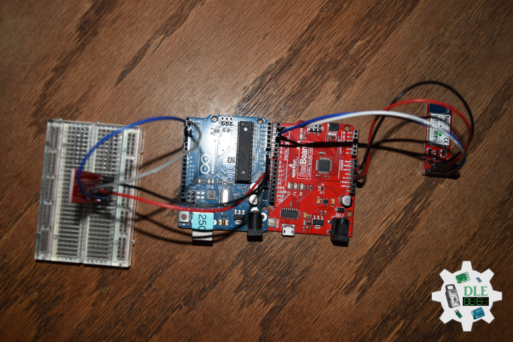
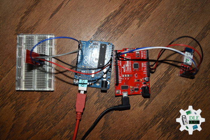
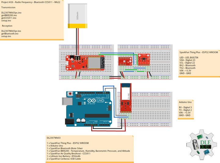
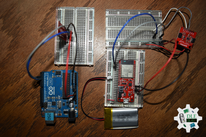
DL2307Mk03
1 x SparkFun Thing Plus – ESP32 WROOM
1 x Arduino Uno
1 x SparkFun Bluetooth Mate Silver
1 x SparkFun BME280 – Temperature, Humidity, Barometric Pressure, and Altitude
1 x SparkFun Air Quality Breakout – CCS811
1 x Lithium Ion Battery – 850mAh
2 x SparkFun Cerberus USB Cable
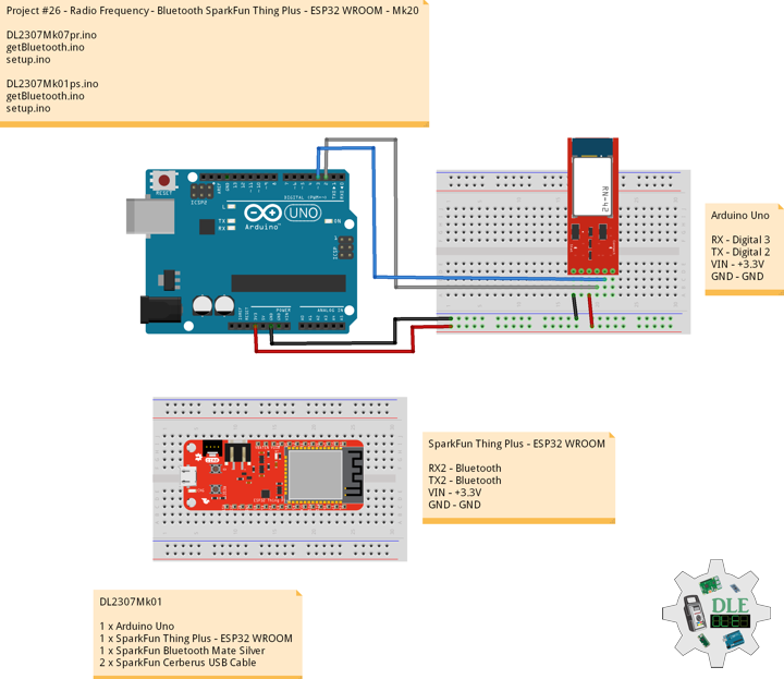
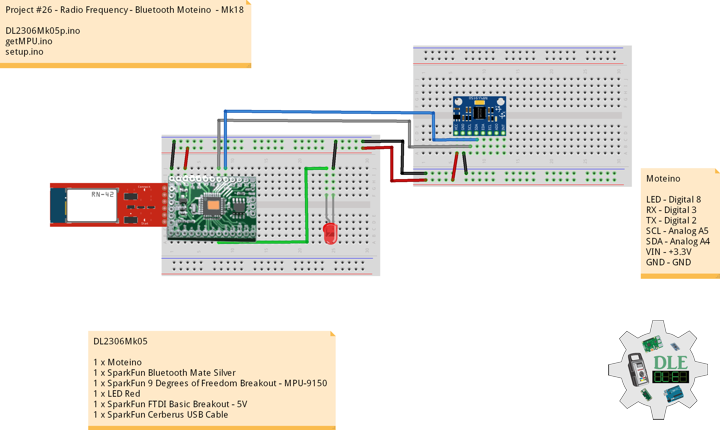
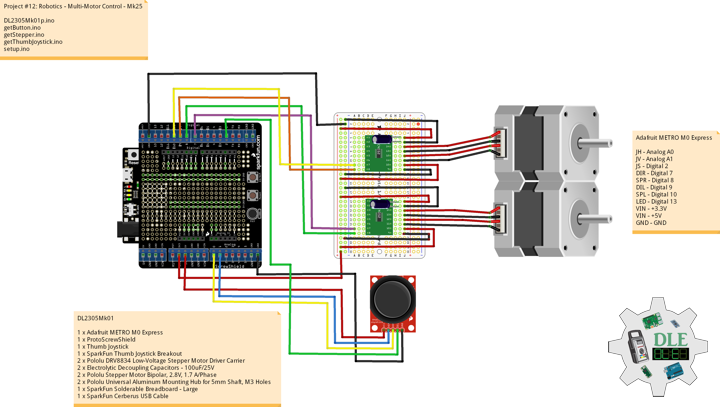
SparkFun Thing Plus – ESP32 WROOM
LED – LED_BUILTIN
SDA – Digital 23
SCL – Digital 22
RX2 – Bluetooth
TX2 – Bluetooth
VIN – +3.3V
GND – GND
——
DL2307Mk03ps.ino
/* ***** Don Luc Electronics © *****
Software Version Information
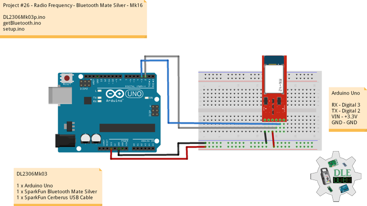
Project #26 - Radio Frequency - SparkFun CCS811 - Mk22
26-22
DL2307Mk03pr.ino
1 x SparkFun Thing Plus - ESP32 WROOM
1 x Arduino Uno
1 x SparkFun Bluetooth Mate Silver
1 x SparkFun BME280 - Temperature, Humidity, Barometric Pressure, and Altitude
1 x SparkFun Air Quality Breakout - CCS811
1 x Lithium Ion Battery - 850mAh
2 x SparkFun Cerberus USB Cable
*/
// Include the Library Code
// Bluetooth Serial
#include "BluetoothSerial.h"
#if !defined(CONFIG_BT_ENABLED) || !defined(CONFIG_BLUEDROID_ENABLED)
#error Bluetooth is not enabled! Please run `make menuconfig` to and enable it
#endif
// Two Wire Interface (TWI/I2C)
#include <Wire.h>
// SparkFun BME280 - Temperature, Humidity, Barometric Pressure, and Altitude
#include <SparkFunBME280.h>
// SparkFun CCS811 - eCO2 & tVOC
#include <SparkFunCCS811.h>
// Bluetooth Serial
BluetoothSerial SerialBT;
// SparkFun BME280 - Temperature, Humidity, Barometric Pressure, and Altitude
BME280 myBME280;
float BMEtempC = 0;
float BMEhumid = 0;
float BMEpressure = 0;
float BMEaltitudeM = 0;
String FullString = "";
// SparkFun CCS811 - eCO2 & tVOC
// Default I2C Address
#define CCS811_ADDR 0x5B
CCS811 myCCS811(CCS811_ADDR);
float CCS811CO2 = 0;
float CCS811TVOC = 0;
String FullStringA = "";
// Software Version Information
String sver = "26-22";
void loop() {
// SparkFun BME280 - Temperature, Humidity, Barometric Pressure, and Altitude
isBME280();
// SparkFun CCS811 - eCO2 & tVOC
isCCS811();
// Delay 1 sec
delay(1000);
}
getBME280.ino
// SparkFun BME280 - Temperature, Humidity, Barometric Pressure, and Altitude
// isBME280 - Temperature, Humidity, Barometric Pressure, and Altitude
void isBME280(){

  // Temperature Celsius
  BMEtempC = myBME280.readTempC();
  // Humidity
  BMEhumid = myBME280.readFloatHumidity();
  // Barometric Pressure
  BMEpressure = myBME280.readFloatPressure();
  // Altitude Meters
  BMEaltitudeM = (myBME280.readFloatAltitudeMeters(), 2);

  // FullString
  FullString = "Temperature = " + String(BMEtempC,2) + " Humidity = "
  + String(BMEhumid,2) + " Barometric = " + String(BMEpressure,2)
  + " Altitude Meters = " + String(BMEaltitudeM,2) + "\r\n";

  // FullString Bluetooth Serial + Serial
  for(int i = 0; i < FullString.length(); i++)
  {

    // Bluetooth Serial
    SerialBT.write(FullString.c_str()[i]);
    // Serial
    Serial.write(FullString.c_str()[i]);

  }

}
getCCS811.ino
// CCS811 - eCO2 & tVOC
// isCCS811 - eCO2 & tVOC
void isCCS811(){

  // This sends the temperature & humidity data to the CCS811
  myCCS811.setEnvironmentalData(BMEhumid, BMEtempC);

  // Calling this function updates the global tVOC and eCO2 variables
  myCCS811.readAlgorithmResults();

  // eCO2 Concentration
  CCS811CO2 = myCCS811.getCO2();

  // tVOC Concentration
  CCS811TVOC = myCCS811.getTVOC();

  // FullStringA
  FullStringA = "TVOCs = " + String(CCS811TVOC,2) + " eCO2 = "
  + String(CCS811CO2,2) + "\r\n";

  // FullStringA Bluetooth Serial + Serial
  for(int i = 0; i < FullStringA.length(); i++)
  {

    // Bluetooth Serial
    SerialBT.write(FullStringA.c_str()[i]);
    // Serial
    Serial.write(FullStringA.c_str()[i]);

  }

}
setup.ino
// Setup
void setup()
{

  // Serial Begin
  Serial.begin(9600);
  Serial.println("Starting BLE work!");

  // Bluetooth Serial
  SerialBT.begin("Don Luc Electronics");
  Serial.println("Bluetooth Started! Ready to pair...");

  // Give display time to power on
  delay(100);

  // Wire - Inialize I2C Hardware
  Wire.begin();

  // Give display time to power on
  delay(100);

  // SparkFun BME280 - Temperature, Humidity, Barometric Pressure, and Altitude
  myBME280.begin();

  // CCS811 - eCO2 & tVOC
  myCCS811.begin();

  // Initialize digital pin LED_BUILTIN as an output
  pinMode(LED_BUILTIN, OUTPUT);
  // Turn the LED on HIGH
  digitalWrite(LED_BUILTIN, HIGH);

}
——
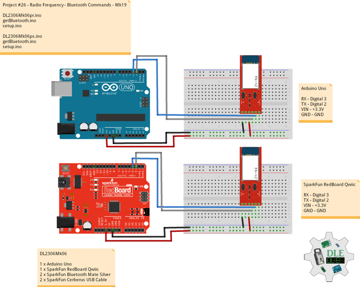
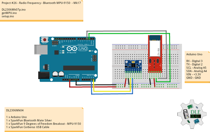
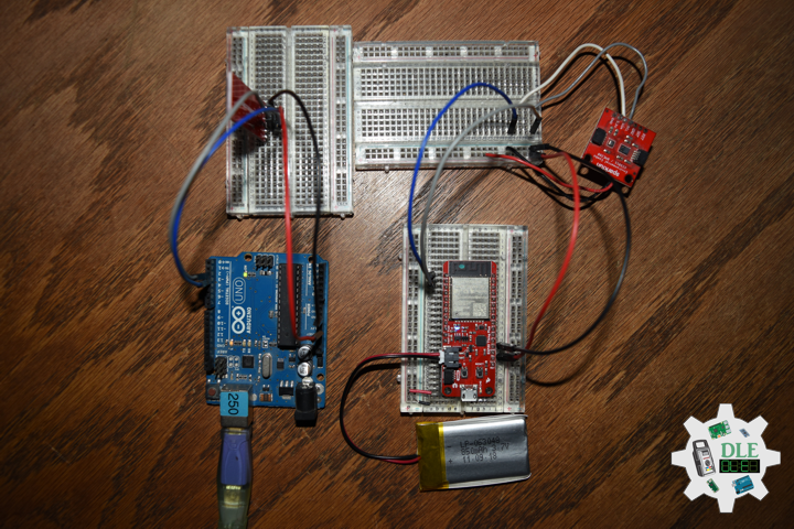
Arduino Uno
RX – Digital 3
TX – Digital 2
VIN – +3.3V
GND – GND
DL2307Mk03pr.ino
/* ***** Don Luc Electronics © *****
Software Version Information
Project #26 - Radio Frequency - Bluetooth CCS811 - Mk22
26-22
DL2307Mk03pr.ino
1 x Arduino Uno
1 x SparkFun RedBoard Qwiic
1 x SparkFun Bluetooth Mate Silver
1 x SparkFun BME280 - Temperature, Humidity, Barometric Pressure, and Altitude
1 x SparkFun Air Quality Breakout - CCS811
1 x Lithium Ion Battery - 850mAh
2 x SparkFun Cerberus USB Cable
*/

// Include the Library Code
// Software Serial
#include <SoftwareSerial.h>

// Software Serial
// TX-O pin of bluetooth mate, Arduino D2
int bluetoothTx = 2;
// RX-I pin of bluetooth mate, Arduino D3
int bluetoothRx = 3;
// Bluetooth
SoftwareSerial bluetooth(bluetoothTx, bluetoothRx);
// BTA
//String BTA = "0006664FDC9E";

// Software Version Information
String sver = "26-22";

void loop() {

  // isBluetooth
  isBluetooth();

}
getBluetooth.ino
// Bluetooth
// Setup Bluetooth
void isSetupBluetooth(){

  // Setup Bluetooth
  // Begin the serial monitor at 9600bps
  Serial.begin(9600);
  // Bluetooth
  // The Bluetooth Mate defaults to 115200bps
  bluetooth.begin(115200);
  // Print three times individually
  bluetooth.print("$");
  bluetooth.print("$");
  bluetooth.print("$");
  // Enter command mode
  // Short delay, wait for the Mate to send back CMD
  delay(100);
  // Temporarily Change the baudrate to 9600, no parity
  bluetooth.println("U,9600,N");
  // 115200 can be too fast at times for NewSoftSerial to relay the data reliably
  // Start bluetooth serial at 9600
  bluetooth.begin(9600);

}
// isBluetooth
void isBluetooth() {

  // If the bluetooth sent any characters
  if(bluetooth.available())
  {

    // Send any characters the bluetooth prints to the serial monitor
    Serial.print((char)bluetooth.read());

  }
  // If stuff was typed in the serial monitor
  if(Serial.available())
  {

    // Send any characters the Serial monitor prints to the bluetooth
    bluetooth.print((char)Serial.read());

  }

}
setup.ino
// Setup
void setup()
{

  // Setup Bluetooth
  isSetupBluetooth();

}
——
People can contact us: https://www.donluc.com/?page_id=1927
Technology Experience
- Programming Language
- Single-Board Microcontrollers (PIC, Arduino, Raspberry Pi,Espressif, etc…)
- IoT
- Wireless (Radio Frequency, Bluetooth, WiFi, Etc…)
- Robotics
- Camera and Video Capture Receiver Stationary, Wheel/Tank and Underwater Vehicle
- Unmanned Vehicles Terrestrial and Marine
- Machine Learning
- RTOS
- Research & Development (R & D)
Instructor, E-Mentor, STEAM, and Arts-Based Training
- Programming Language
- IoT
- PIC Microcontrollers
- Arduino
- Raspberry Pi
- Espressif
- Robotics
Follow Us
Luc Paquin – Curriculum Vitae – 2023
https://www.donluc.com/luc/
Web: https://www.donluc.com/
Facebook: https://www.facebook.com/neosteam.labs.9/
YouTube: https://www.youtube.com/@thesass2063
Twitter: https://twitter.com/labs_steam
Pinterest: https://www.pinterest.com/NeoSteamLabs/
Instagram: https://www.instagram.com/neosteamlabs/
Don Luc