——
#DonLucElectronics #DonLuc #RadioFrequency #Bluetooth #UUID #Display #SparkFun #Adafruit #BME280 #CCS811 #Arduino #Project #Fritzing #Programming #Electronics #Microcontrollers #Consultant
——
——
——
——
Universally Unique IDentifier
A Universally Unique IDentifier (UUID) is a 128-bit label used for information in computer systems. When generated according to the standard methods, UUIDs are, for practical purposes, unique. Their uniqueness does not depend on a central registration authority or coordination between the parties generating them, unlike most other numbering schemes. While the probability that a UUID will be duplicated is not zero, it is generally considered close enough to zero to be negligible.
Thus, anyone can create a UUID and use it to identify something with near certainty that the identifier does not duplicate one that has already been, or will be, created to identify something else. Information labeled with UUIDs by independent parties can therefore be later combined into a single database or transmitted on the same channel, with a negligible probability of duplication. Adoption of UUIDs is widespread, with many computing platforms providing support for generating them and for parsing their textual representation.
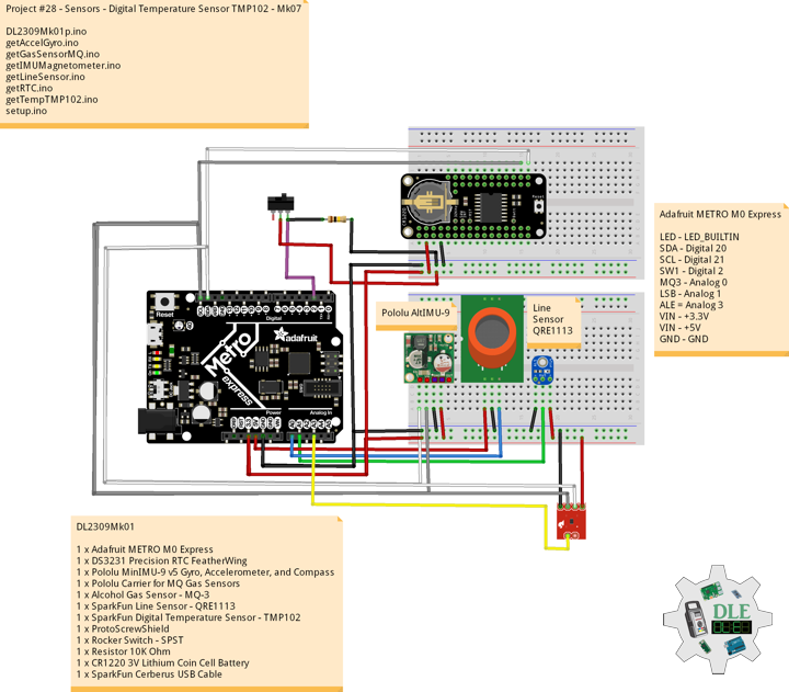
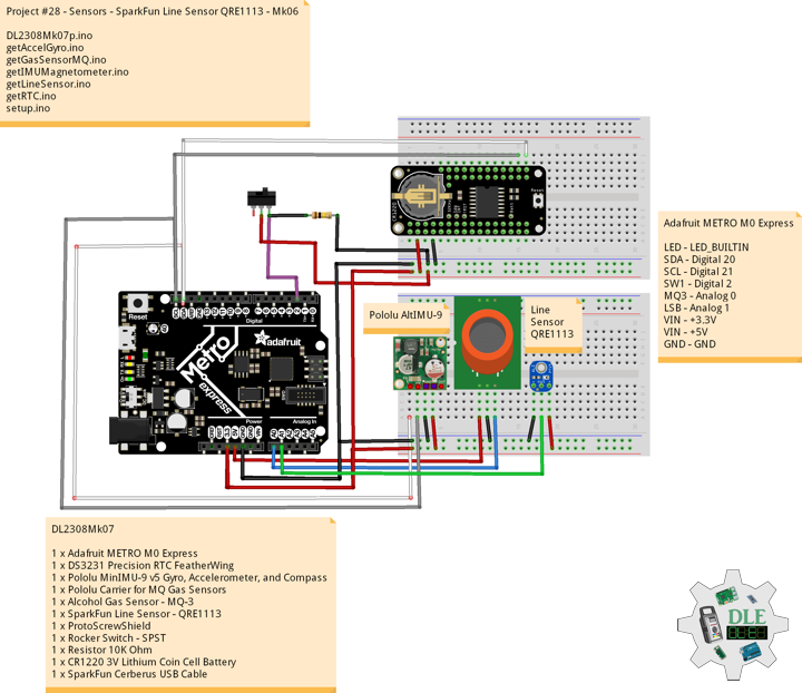
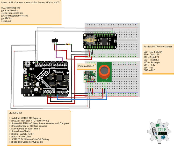
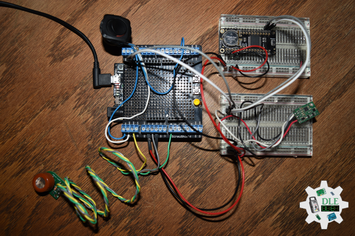
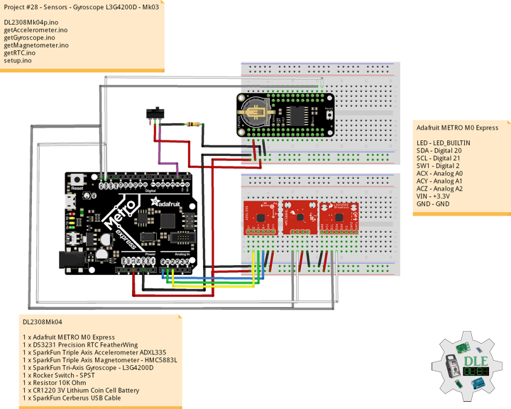
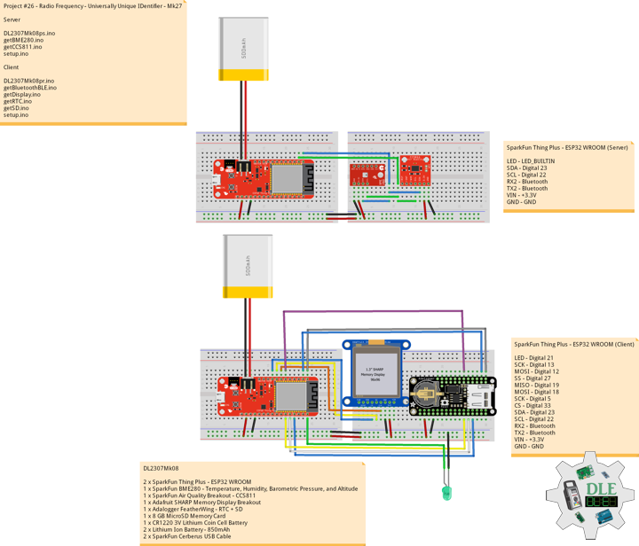
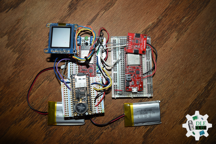
DL2307Mk08
2 x SparkFun Thing Plus – ESP32 WROOM
1 x SparkFun BME280 – Temperature, Humidity, Barometric Pressure, and Altitude
1 x SparkFun Air Quality Breakout – CCS811
1 x Adafruit SHARP Memory Display Breakout
1 x Adalogger FeatherWing – RTC + SD
1 x 8 GB MicroSD Memory Card
1 x CR1220 3V Lithium Coin Cell Battery
2 x Lithium Ion Battery – 850mAh
2 x SparkFun Cerberus USB Cable
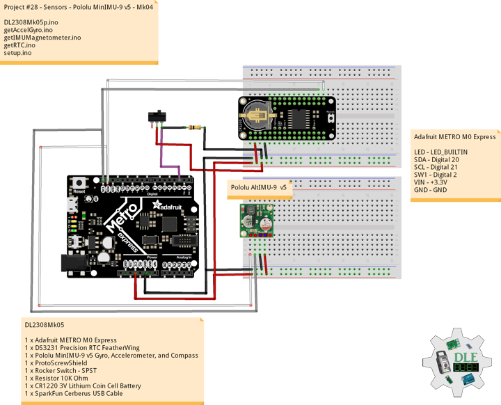
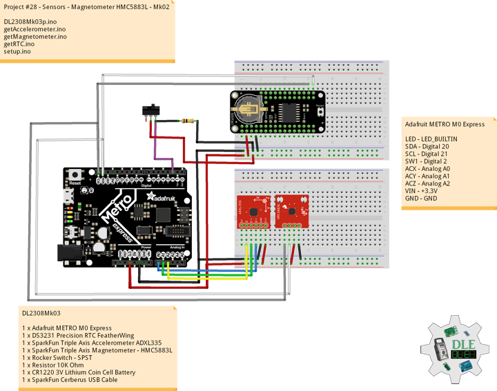
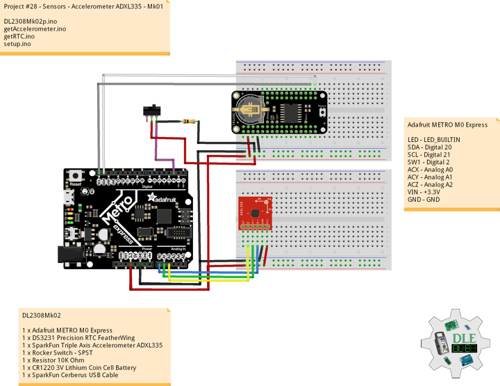
SparkFun Thing Plus – ESP32 WROOM (Server)
LED – LED_BUILTIN
SDA – Digital 23
SCL – Digital 22
RX2 – Bluetooth
TX2 – Bluetooth
VIN – +3.3V
GND – GND
——
DL2307Mk08ps.ino
/* ***** Don Luc Electronics © *****
Software Version Information
Project #26 - Radio Frequency - Universally Unique IDentifier - Mk27
26-27
DL2307Mk08ps.ino
2 x SparkFun Thing Plus - ESP32 WROOM
1 x SparkFun BME280 - Temperature, Humidity, Barometric Pressure, and Altitude
1 x SparkFun Air Quality Breakout - CCS811
1 x Adafruit SHARP Memory Display Breakout
1 x Adalogger FeatherWing - RTC + SD
1 x 8 GB MicroSD Memory Card
1 x CR1220 3V Lithium Coin Cell Battery
2 x Lithium Ion Battery - 850mAh
2 x SparkFun Cerberus USB Cable
*/

// Include the Library Code
// BLE Device
#include <BLEDevice.h>
// BLE Utils
#include <BLEUtils.h>
// BLE Serve
#include <BLEServer.h>
// Two Wire Interface (TWI/I2C)
#include <Wire.h>
// SparkFun BME280 - Temperature, Humidity, Barometric Pressure, and Altitude
#include <SparkFunBME280.h>
// SparkFun CCS811 - eCO2 & tVOC
#include <SparkFunCCS811.h>

// See the following for generating UUIDs:
// https://www.uuidgenerator.net/
#define SERVICE_UUID            "7c394dc4-49a8-4c22-8a5b-b1612d8c13c1"
#define CHARACTERISTIC_UUID     "a4c4cec2-f394-4f7a-b9de-89047feca74b"
#define CHARACTERISTIC_TEM_UUID "74bd92c6-89d0-4387-823e-97e7e0fb7a2b"
#define CHARACTERISTIC_HUM_UUID "1b63f246-b97f-4d2e-b8eb-f69e20a23a34"
#define CHARACTERISTIC_BAR_UUID "43788175-37a7-4280-93c6-c690324d088e"
#define CHARACTERISTIC_ALT_UUID "609deed9-a72d-45c3-aaba-14a73b0d8fda"
#define CHARACTERISTIC_ECO_UUID "ab17aace-c0b9-4bd3-bb93-7715d9afaeea"
#define CHARACTERISTIC_VOC_UUID "6a8bf86a-9d40-457c-9f7f-f13a3d6803f1"
// Makes the chracteristic globlal
static BLECharacteristic *pCharacteristicTEM;
static BLECharacteristic *pCharacteristicHUM;
static BLECharacteristic *pCharacteristicBAR;
static BLECharacteristic *pCharacteristicALT;
static BLECharacteristic *pCharacteristicECO;
static BLECharacteristic *pCharacteristicVOC;

// SparkFun BME280 - Temperature, Humidity, Barometric Pressure, and Altitude
BME280 myBME280;
float BMEtempC = 0;
float BMEhumid = 0;
float BMEpressure = 0;
float BMEaltitudeM = 0;
String FullString = "";

// SparkFun CCS811 - eCO2 & tVOC
// Default I2C Address
#define CCS811_ADDR 0x5B
CCS811 myCCS811(CCS811_ADDR);
float CCS811CO2 = 0;
float CCS811TVOC = 0;
String FullStringA = "";

// Software Version Information
String sver = "26-27";

void loop() {

  // SparkFun BME280 - Temperature, Humidity, Barometric Pressure, and Altitude
  isBME280();

  // SparkFun CCS811 - eCO2 & tVOC
  isCCS811();

  // Delay 1 sec
  delay(1000);

}
getBME280.ino
// SparkFun BME280 - Temperature, Humidity, Barometric Pressure, and Altitude
// isBME280 - Temperature, Humidity, Barometric Pressure, and Altitude
void isBME280(){

  // Temperature Celsius
  BMEtempC = myBME280.readTempC();
  // Humidity
  BMEhumid = myBME280.readFloatHumidity();
  // Barometric Pressure
  BMEpressure = myBME280.readFloatPressure();
  // Altitude Meters
  BMEaltitudeM = (myBME280.readFloatAltitudeMeters(), 2);

  // setValue takes uint8_t, uint16_t, uint32_t, int, float, double and string
  pCharacteristicTEM->setValue(BMEtempC);
  pCharacteristicHUM->setValue(BMEhumid);
  pCharacteristicBAR->setValue(BMEpressure);
  pCharacteristicALT->setValue(BMEaltitudeM);

  // FullString
  FullString = "Temperature = " + String(BMEtempC,2) + " Humidity = "
  + String(BMEhumid,2) + " Barometric = " + String(BMEpressure,2)
  + " Altitude Meters = " + String(BMEaltitudeM,2) + "\r\n";

  // FullString Bluetooth Serial + Serial
  for(int i = 0; i < FullString.length(); i++)
  {

    // Serial
    Serial.write(FullString.c_str()[i]);

  }

}
getCCS811.ino
// CCS811 - eCO2 & tVOC
// isCCS811 - eCO2 & tVOC
void isCCS811(){

  // This sends the temperature & humidity data to the CCS811
  myCCS811.setEnvironmentalData(BMEhumid, BMEtempC);

  // Calling this function updates the global tVOC and eCO2 variables
  myCCS811.readAlgorithmResults();

  // eCO2 Concentration
  CCS811CO2 = myCCS811.getCO2();

  // tVOC Concentration
  CCS811TVOC = myCCS811.getTVOC();

  // setValue takes uint8_t, uint16_t, uint32_t, int, float, double and string
  pCharacteristicECO->setValue(CCS811CO2);
  pCharacteristicVOC->setValue(CCS811TVOC);

  // FullStringA
  FullStringA = "TVOCs = " + String(CCS811TVOC,2) + " eCO2 = "
  + String(CCS811CO2,2) + "\r\n";

  // FullStringA Bluetooth Serial + Serial
  for(int i = 0; i < FullStringA.length(); i++)
  {

    // Serial
    Serial.write(FullStringA.c_str()[i]);

  }


}
setup.ino
// Setup
void setup()
{

  // Serial Begin
  Serial.begin(115200);
  Serial.println("Starting BLE work!");

  // Give display time to power on
  delay(100);

  // Wire - Inialize I2C Hardware
  Wire.begin();

  // Give display time to power on
  delay(100);

  // SparkFun BME280 - Temperature, Humidity, Barometric Pressure, and Altitude
  myBME280.begin();

  // CCS811 - eCO2 & tVOC
  myCCS811.begin();

  // Initialize digital pin LED_BUILTIN as an output
  pinMode(LED_BUILTIN, OUTPUT);
  // Turn the LED on HIGH
  digitalWrite(LED_BUILTIN, HIGH);

  // BLE Device Init
  BLEDevice::init("Don Luc Electronics Server");
  BLEServer *pServer = BLEDevice::createServer();
  BLEService *pService = pServer->createService(SERVICE_UUID);
  BLECharacteristic *pCharacteristic = pService->createCharacteristic(
                                         CHARACTERISTIC_UUID,
                                         BLECharacteristic::PROPERTY_READ |
                                         BLECharacteristic::PROPERTY_WRITE
                                       );

  pCharacteristicTEM = pService->createCharacteristic(
                                         CHARACTERISTIC_TEM_UUID,
                                         BLECharacteristic::PROPERTY_READ |
                                         BLECharacteristic::PROPERTY_WRITE
                                       );

  pCharacteristicHUM = pService->createCharacteristic(
                                         CHARACTERISTIC_HUM_UUID,
                                         BLECharacteristic::PROPERTY_READ |
                                         BLECharacteristic::PROPERTY_WRITE
                                       );

  pCharacteristicBAR = pService->createCharacteristic(
                                         CHARACTERISTIC_BAR_UUID,
                                         BLECharacteristic::PROPERTY_READ |
                                         BLECharacteristic::PROPERTY_WRITE
                                       );

  pCharacteristicALT = pService->createCharacteristic(
                                         CHARACTERISTIC_ALT_UUID,
                                         BLECharacteristic::PROPERTY_READ |
                                         BLECharacteristic::PROPERTY_WRITE
                                       );

  pCharacteristicVOC = pService->createCharacteristic(
                                         CHARACTERISTIC_VOC_UUID,
                                         BLECharacteristic::PROPERTY_READ |
                                         BLECharacteristic::PROPERTY_WRITE
                                       );

  pCharacteristicECO = pService->createCharacteristic(
                                         CHARACTERISTIC_ECO_UUID,
                                         BLECharacteristic::PROPERTY_READ |
                                         BLECharacteristic::PROPERTY_WRITE
                                       );

  pCharacteristic->setValue("Luc Paquin");
  pService->start();

  // This still is working for backward compatibility
  // BLEAdvertising *pAdvertising = pServer->getAdvertising();
  // BLE Advertising
  BLEAdvertising *pAdvertising = BLEDevice::getAdvertising();
  pAdvertising->addServiceUUID(SERVICE_UUID);
  pAdvertising->setScanResponse(true);
  // Functions that help with iPhone connections issue
  pAdvertising->setMinPreferred(0x06);
  pAdvertising->setMinPreferred(0x12);
  BLEDevice::startAdvertising();

}
——
SparkFun Thing Plus – ESP32 WROOM (Client)
LED – Digital 21
SCK – Digital 13
MOSI – Digital 12
SS – Digital 27
MISO – Digital 19
MOSI – Digital 18
SCK – Digital 5
CS – Digital 33
SDA – Digital 23
SCL – Digital 22
RX2 – Bluetooth
TX2 – Bluetooth
VIN – +3.3V
GND – GND
——
DL2307Mk08pr.ino
/* ***** Don Luc Electronics © *****
Software Version Information
Project #26 - Radio Frequency - Universally Unique IDentifier - Mk27
26-27
DL2307Mk08pr.ino
2 x SparkFun Thing Plus - ESP32 WROOM
1 x SparkFun BME280 - Temperature, Humidity, Barometric Pressure, and Altitude
1 x SparkFun Air Quality Breakout - CCS811
1 x Adafruit SHARP Memory Display Breakout
1 x Adalogger FeatherWing - RTC + SD
1 x 8 GB MicroSD Memory Card
1 x CR1220 3V Lithium Coin Cell Battery
2 x Lithium Ion Battery - 850mAh
2 x SparkFun Cerberus USB Cable
*/

// Include the Library Code
// Bluetooth BLE Device
#include "BLEDevice.h"
// SHARP Memory Display
#include <Adafruit_SharpMem.h>
// Adafruit GFX Library
#include <Adafruit_GFX.h>
// Date and Time
#include "RTClib.h"
// SD Card
#include "FS.h"
#include "SD.h"
#include "SPI.h"

// SHARP Memory Display
// any pins can be used
#define SHARP_SCK  13
#define SHARP_MOSI 12
#define SHARP_SS   27
// Set the size of the display here, e.g. 144x168!
Adafruit_SharpMem display(SHARP_SCK, SHARP_MOSI, SHARP_SS, 144, 168);
// The currently-available SHARP Memory Display (144x168 pixels)
// requires > 4K of microcontroller RAM; it WILL NOT WORK on Arduino Uno
// or other <4K "classic" devices.
#define BLACK 0
#define WHITE 1
// 1/2 of lesser of display width or height
int minorHalfSize;

// The remote service we wish to connect to.
static BLEUUID serviceUUID("7c394dc4-49a8-4c22-8a5b-b1612d8c13c1");
// The characteristic of the remote service we are interested in.
static BLEUUID    charUUID("a4c4cec2-f394-4f7a-b9de-89047feca74b");
// Use the same UUID as on the server
static BLEUUID    charTEMUUID("74bd92c6-89d0-4387-823e-97e7e0fb7a2b");
static BLEUUID    charHUMUUID("1b63f246-b97f-4d2e-b8eb-f69e20a23a34");
static BLEUUID    charBARUUID("43788175-37a7-4280-93c6-c690324d088e");
static BLEUUID    charALTUUID("609deed9-a72d-45c3-aaba-14a73b0d8fda");
static BLEUUID    charECOUUID("ab17aace-c0b9-4bd3-bb93-7715d9afaeea");
static BLEUUID    charVOCUUID("6a8bf86a-9d40-457c-9f7f-f13a3d6803f1");
static boolean doConnect = false;
static boolean connected = false;
static boolean doScan = false;
static BLERemoteCharacteristic* pRemoteCharacteristic;
static BLERemoteCharacteristic* pRemoteCharacteristicTEM;
static BLERemoteCharacteristic* pRemoteCharacteristicHUM;
static BLERemoteCharacteristic* pRemoteCharacteristicBAR;
static BLERemoteCharacteristic* pRemoteCharacteristicALT;
static BLERemoteCharacteristic* pRemoteCharacteristicECO;
static BLERemoteCharacteristic* pRemoteCharacteristicVOC;

static BLEAdvertisedDevice* myDevice;
float TEMValue;
float HUMValue;
float BARValue;
float ALTValue;
float ECOValue;
float VOCValue;

int iLED = 21;

// Date and Time
// PCF8523 Precision RTC
RTC_PCF8523 rtc;
String dateRTC = "";
String timeRTC = "";

// microSD Card
const int chipSelect = 33;
String zzzzzz = "";

// Software Version Information
String sver = "26-27";

void loop() {

  // Bluetooth BLE
  isBluetoothBLE();

  // Date and Time
  isRTC();

  // Display Environmental
  isDisplayEnvironmental();

  // microSD Card
  isSD();

}
getBluetoothBLE.ino
// Bluetooth BLE
// isBluetoothBLE
void isBluetoothBLE(){

  // If the flag "doConnect" is true then we have scanned for
  // and found the desired
  // BLE Server with which we wish to connect.  Now we connect to it.
  // Once we are connected we set the connected flag to be true.
  if (doConnect == true) {
    if (connectToServer()) {
      Serial.println("We are now connected to the BLE Server.");
    } else {
      Serial.println("We have failed to connect to the server; there is nothin more we will do.");
    }
    doConnect = false;
  }

  // If we are connected to a peer BLE Server, update the characteristic each time we are reached
  // with the current time since boot.
  if (connected) {
    String newValue = "Time since boot: " + String(millis()/1000);
    //Serial.println("Setting new characteristic value to \"" + newValue + "\"");

    // Set the characteristic's value to be the array of bytes that is actually a string.
   // pRemoteCharacteristic->writeValue(newValue.c_str(), newValue.length());//***********JKO
  }else if(doScan){
    BLEDevice::getScan()->start(0);  // this is just example to start scan after disconnect, most likely there is better way to do it in arduino
  }

  // read the Characteristics and store them in a variable
  // This also makes the print command do float handling
  TEMValue = pRemoteCharacteristicTEM->readFloat();
  HUMValue = pRemoteCharacteristicHUM->readFloat();
  BARValue = pRemoteCharacteristicBAR->readFloat();
  ALTValue = pRemoteCharacteristicALT->readFloat();
  ECOValue = pRemoteCharacteristicECO->readFloat();
  VOCValue = pRemoteCharacteristicVOC->readFloat();

}
// Notify Callback
static void notifyCallback(
  BLERemoteCharacteristic* pBLERemoteCharacteristic,
  uint8_t* pData,
  size_t length,
  bool isNotify) {
    Serial.print("Notify callback for characteristic ");
    Serial.print(pBLERemoteCharacteristic->getUUID().toString().c_str());
    Serial.print(" of data length ");
    Serial.println(length);
    Serial.print("data: ");
    Serial.println((char*)pData);
}
// My Client Callback
class MyClientCallback : public BLEClientCallbacks {
  void onConnect(BLEClient* pclient) {
  }

  void onDisconnect(BLEClient* pclient) {
    connected = false;
    Serial.println("onDisconnect");
  }
};
// Connect To Server
bool connectToServer() {
    Serial.print("Forming a connection to ");
    Serial.println(myDevice->getAddress().toString().c_str());

    BLEClient*  pClient  = BLEDevice::createClient();
    Serial.println(" - Created client");

    pClient->setClientCallbacks(new MyClientCallback());

    // Connect to the remove BLE Server.
    // if you pass BLEAdvertisedDevice instead of address,
    //it will be recognized type of peer device address (public or private)
    pClient->connect(myDevice);
    Serial.println(" - Connected to server");
    //set client to request maximum MTU from server (default is 23 otherwise)
    pClient->setMTU(517);

    // Obtain a reference to the service we are after in the remote BLE server.
    BLERemoteService* pRemoteService = pClient->getService(serviceUUID);
    if (pRemoteService == nullptr) {
      Serial.print("Failed to find our service UUID: ");
      Serial.println(serviceUUID.toString().c_str());
      pClient->disconnect();
      return false;
    }
    Serial.println(" - Found our service");

    // Obtain a reference to the characteristic in the service of the remote BLE server.
    pRemoteCharacteristic = pRemoteService->getCharacteristic(charUUID);
    if (pRemoteCharacteristic == nullptr) {
      Serial.print("Failed to find our characteristic UUID: ");
      Serial.println(charUUID.toString().c_str());
      pClient->disconnect();
      return false;
    }
    Serial.println(" - Found our characteristic");
    // Temperature Obtain a reference to the characteristic in the service
    // of the remote BLE server.
    pRemoteCharacteristicTEM = pRemoteService->getCharacteristic(charTEMUUID);
    if (pRemoteCharacteristicTEM == nullptr) {
      Serial.print("Failed to find our characteristic UUID Temperature: ");
      Serial.println(charTEMUUID.toString().c_str());
      pClient->disconnect();
      return false;
    }
    // Humidity Obtain a reference to the characteristic in the service
    // of the remote BLE server.
    pRemoteCharacteristicHUM = pRemoteService->getCharacteristic(charHUMUUID);
    if (pRemoteCharacteristicHUM == nullptr) {
      Serial.print("Failed to find our characteristic UUID Temperature: ");
      Serial.println(charHUMUUID.toString().c_str());
      pClient->disconnect();
      return false;
    }

    Serial.println(" - Found our characteristic");

    // Barometric Obtain a reference to the characteristic in the service
    // of the remote BLE server.
    pRemoteCharacteristicBAR = pRemoteService->getCharacteristic(charBARUUID);
    if (pRemoteCharacteristicBAR == nullptr) {
      Serial.print("Failed to find our characteristic UUID Barometric: ");
      Serial.println(charBARUUID.toString().c_str());
      pClient->disconnect();
      return false;
    }

    Serial.println(" - Found our characteristic");

    // Altitude Obtain a reference to the characteristic in the service
    // of the remote BLE server.
    pRemoteCharacteristicALT = pRemoteService->getCharacteristic(charALTUUID);
    if (pRemoteCharacteristicALT == nullptr) {
      Serial.print("Failed to find our characteristic UUID Altitude: ");
      Serial.println(charALTUUID.toString().c_str());
      pClient->disconnect();
      return false;
    }

    // eCO2 Concentration Obtain a reference to the characteristic in the service
    // of the remote BLE server.
    pRemoteCharacteristicECO = pRemoteService->getCharacteristic(charECOUUID);
    if (pRemoteCharacteristicECO == nullptr) {
      Serial.print("Failed to find our characteristic UUID eCO2 Concentration: ");
      Serial.println(charECOUUID.toString().c_str());
      pClient->disconnect();
      return false;
    }

    Serial.println(" - Found our characteristic");

    // tVOC Concentration Obtain a reference to the characteristic in the service
    // of the remote BLE server.
    pRemoteCharacteristicVOC = pRemoteService->getCharacteristic(charVOCUUID);
    if (pRemoteCharacteristicVOC == nullptr) {
      Serial.print("Failed to find our characteristic UUID tVOC Concentration: ");
      Serial.println(charVOCUUID.toString().c_str());
      pClient->disconnect();
      return false;
    }


    Serial.println(" - Found our characteristic");
    // Read the value of the characteristic.
    if(pRemoteCharacteristic->canRead()) {
      std::string value = pRemoteCharacteristic->readValue();
      Serial.print("The characteristic value was: ");
      Serial.println(value.c_str());
    }

    if(pRemoteCharacteristic->canNotify())
      pRemoteCharacteristic->registerForNotify(notifyCallback);

    connected = true;
    return true;

}
/**
 * Scan for BLE servers and find the first one that advertises the service we are looking for.
 */
class MyAdvertisedDeviceCallbacks: public BLEAdvertisedDeviceCallbacks {
 /**
   * Called for each advertising BLE server.
   */
  void onResult(BLEAdvertisedDevice advertisedDevice) {
    Serial.print("BLE Advertised Device found: ");
    Serial.println(advertisedDevice.toString().c_str());

    // We have found a device, let us now see if it contains the service we are looking for.
    if (advertisedDevice.haveServiceUUID() && advertisedDevice.isAdvertisingService(serviceUUID)) {

      BLEDevice::getScan()->stop();
      myDevice = new BLEAdvertisedDevice(advertisedDevice);
      doConnect = true;
      doScan = true;

    } // Found our server
  } // onResult
}; // MyAdvertisedDeviceCallbacks
getDisplay.ino
// Display
// SHARP Memory Display - UID
void isDisplayUID() {
// Text Display
// Clear Display
display.clearDisplay();
display.setRotation(2);
display.setTextSize(3);
display.setTextColor(BLACK);
// Don Luc Electronics
display.setCursor(0,10);
display.println( "Don Luc" );
display.setTextSize(2);
display.setCursor(0,40);
display.println( "Electronics" );
// Version
display.setTextSize(3);
display.setCursor(0,70);
display.println( "Version" );
display.setTextSize(2);
display.setCursor(0,100);
display.println( sver );
display.setCursor(0,125);
display.println( dateRTC );
display.setCursor(0,150);
display.println( timeRTC );
// Refresh
display.refresh();
delay( 5000 );
}
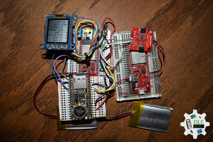
// Display Environmental
void isDisplayEnvironmental(){
// Text Display Environmental
// Clear Display
display.clearDisplay();
display.setRotation(2);
display.setTextSize(2);
display.setTextColor(BLACK);
// Temperature Celsius
display.setCursor(0,5);
display.print( "T: " );
display.print( TEMValue );
display.println( "C" );
// Humidity
display.setCursor(0,25);
display.print( "H: " );
display.print( HUMValue );
display.println( "%" );
// Pressure
display.setCursor(0,45);
display.print( "B: " );
display.print( BARValue );
display.println( "" );
// Altitude Meters
display.setCursor(0,65);
display.print( "A: " );
display.print( ALTValue );
display.println( "M" );
// eCO2 Concentration
display.setCursor(0,85);
display.print( "C: " );
display.print( ECOValue );
display.println( "ppm" );
// tVOC Concentration
display.setCursor(0,105);
display.print( "V: " );
display.print( VOCValue );
display.println( "ppb" );
// Date
display.setCursor(0,125);
display.println( dateRTC );
// Time
display.setCursor(0,145);
display.println( timeRTC );
// Refresh
display.refresh();
delay( 100 );
}
getRTC.ino
// Date & Time
// PCF8523 Precision RTC
void setupRTC() {

  // Date & Time
  // pcf8523 Precision RTC
  if (! rtc.begin()) {
    while (1);
  }

  if (! rtc.initialized()) {
    // Following line sets the RTC to the date & time this sketch was compiled
    rtc.adjust(DateTime(F(__DATE__), F(__TIME__)));
    // This line sets the RTC with an explicit date & time, for example to set
    // January 21, 2014 at 3am you would call:
    //rtc.adjust(DateTime(2023, 7, 24, 11, 0, 0));
  }

}
// Date and Time RTC
void isRTC () {

  // Date and Time
  dateRTC = "";
  timeRTC = "";
  DateTime now = rtc.now();

  // Date
  dateRTC = now.year(), DEC;
  dateRTC = dateRTC + "/";
  dateRTC = dateRTC + now.month(), DEC;
  dateRTC = dateRTC + "/";
  dateRTC = dateRTC + now.day(), DEC;

  // Time
  timeRTC = now.hour(), DEC;
  timeRTC = timeRTC + ":";
  timeRTC = timeRTC + now.minute(), DEC;
  timeRTC = timeRTC + ":";
  timeRTC = timeRTC + now.second(), DEC;

}
getSD.ino
// microSD Card
// microSD Setup
void setupSD() {

    // microSD Card
    pinMode( chipSelect , OUTPUT );
    if(!SD.begin( chipSelect )){
        ;
        return;
    }

    uint8_t cardType = SD.cardType();

    if(cardType == CARD_NONE){
        ;
        return;
    }

    //Serial.print("SD Card Type: ");
    if(cardType == CARD_MMC){
        ;
    } else if(cardType == CARD_SD){
        ;
    } else if(cardType == CARD_SDHC){
        ;
    } else {
        ;
    }

    uint64_t cardSize = SD.cardSize() / (1024 * 1024);

}
// microSD Card
void isSD() {

  zzzzzz = "";

  // BLE|Version|Date|Time|Temperature Celsius|Humidity|Barometric Pressure
  //|Altitude Meters|eCO2 Concentration|tVOC Concentration|*
  zzzzzz = "BLE|" + sver + "|" + dateRTC + "|" + timeRTC + "|" + TEMValue
  + "|" + HUMValue + "|" + BARValue + "|" + ALTValue + "|" + ECOValue
  + "|" + VOCValue + "|*\r";

  char msg[zzzzzz.length() + 1];

  zzzzzz.toCharArray(msg, zzzzzz.length() + 1);

  appendFile(SD, "/espdata.txt", msg );

}
// List Dir
void listDir(fs::FS &fs, const char * dirname, uint8_t levels){

    dirname;

    File root = fs.open(dirname);

    if(!root){
        return;
    }

    if(!root.isDirectory()){
        return;
    }

    File file = root.openNextFile();

    while(file){
        if(file.isDirectory()){
            file.name();
            if(levels){
                listDir(fs, file.name(), levels -1);
            }
        } else {
            file.name();
            file.size();
        }
        file = root.openNextFile();
    }

}
// Write File
void writeFile(fs::FS &fs, const char * path, const char * message){

    path;

    File file = fs.open(path, FILE_WRITE);

    if(!file){
        return;
    }

    if(file.print(message)){
        ;
    } else {
        ;
    }

    file.close();

}
// Append File
void appendFile(fs::FS &fs, const char * path, const char * message){

    path;

    File file = fs.open(path, FILE_APPEND);

    if(!file){
        return;
    }

    if(file.print(message)){
        ;
    } else {
        ;
    }

    file.close();

}
setup.ino
// Setup
void setup()
{

  // Serial
  Serial.begin(115200);
  Serial.println("Starting Arduino BLE Client application...");

  // Initialize digital pin iLED as an output
  pinMode(iLED, OUTPUT);
  // Turn the LED on HIGH
  digitalWrite(iLED, HIGH);

  // SHARP Display start & clear the display
  display.begin();
  display.clearDisplay();

  // Date & Time RTC
  // PCF8523 Precision RTC
  setupRTC();

  // Date & Time
  isRTC();

  // Display UID
  isDisplayUID();

  // microSD Card
  setupSD();

  // Bluetooth BLE
  BLEDevice::init("");

  // Give display time to power on
  delay(100);

  BLEScan* pBLEScan = BLEDevice::getScan();
  pBLEScan->setAdvertisedDeviceCallbacks(new MyAdvertisedDeviceCallbacks());
  pBLEScan->setInterval(1349);
  pBLEScan->setWindow(449);
  pBLEScan->setActiveScan(true);
  pBLEScan->start(5, false);

}
——
People can contact us: https://www.donluc.com/?page_id=1927
Technology Experience
- Programming Language
- Single-Board Microcontrollers (PIC, Arduino, Raspberry Pi,Espressif, etc…)
- IoT
- Wireless (Radio Frequency, Bluetooth, WiFi, Etc…)
- Robotics
- Camera and Video Capture Receiver Stationary, Wheel/Tank and Underwater Vehicle
- Unmanned Vehicles Terrestrial and Marine
- Machine Learning
- RTOS
- Research & Development (R & D)
Instructor, E-Mentor, STEAM, and Arts-Based Training
- Programming Language
- IoT
- PIC Microcontrollers
- Arduino
- Raspberry Pi
- Espressif
- Robotics
Follow Us
Luc Paquin – Curriculum Vitae – 2023
https://www.donluc.com/luc/
Web: https://www.donluc.com/
Facebook: https://www.facebook.com/neosteam.labs.9/
YouTube: https://www.youtube.com/@thesass2063
Twitter: https://twitter.com/labs_steam
Pinterest: https://www.pinterest.com/NeoSteamLabs/
Instagram: https://www.instagram.com/neosteamlabs/
Don Luc