——
#DonLucElectronics #DonLuc #NixieTube #Nixie #ArduiNIX #ArduinoUNO #Arduino #Project #Fritzing #Programming #Electronics #Microcontrollers #Consultant
——
——
——
——
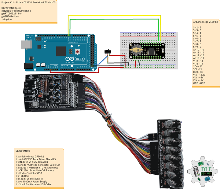
DS3231 Precision RTC FeatherWing
The datasheet for the DS3231 explains that this part is an extremely accurate I²C – Integrated RTC TCXO – crystal. This Real Time Clock (RTC) is the most precise you can get in a small, low power package. Most RTC’s use an external 32kHz timing crystal that is used to keep time with low current draw. That’s all well and good, but those crystals have slight drift, particularly when the temperature changes, the temperature changes the oscillation frequency very slightly but it does add up. This RTC is in a beefy package because the crystal is inside the chip. And right next to the integrated crystal is a temperature sensor. That sensor compensates for the frequency changes by adding or removing clock ticks so that the time keeping stays on schedule.
This is the finest RTC you can get, and now we have it in a compact, breadboard friendly breakout. With a coin cell plugged into the back, you can get years of precision time keeping, even when main power is lost. Great for datalogging and clocks, or anything where you need to really know the time.
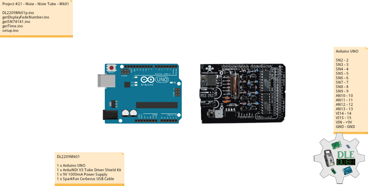
DL2209Mk03
1 x Arduino Mega 2560 R2
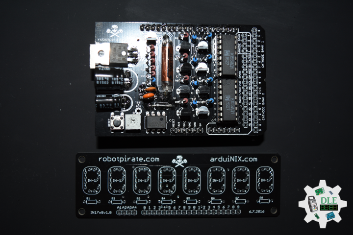
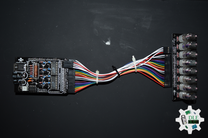
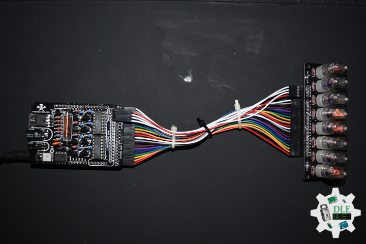
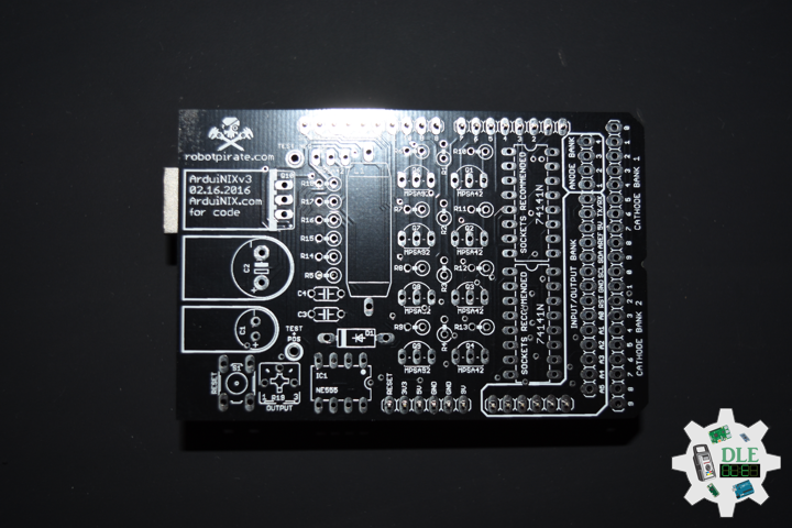
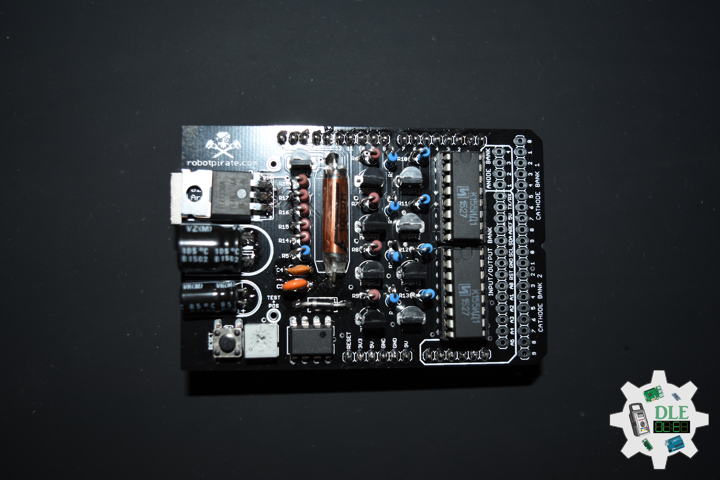
1 x ArduiNIX V3 Tube Driver Shield Kit
1 x IN-17×8 V1 Tube Board Kit
1 x Anode / Cathode Connector Cable Set
1 x DS3231 Precision RTC FeatherWing
1 x CR1220 12mm Coin Cell Battery
1 x Rocker Switch – SPST
1 x 10K Ohm
1 x SparkFun ProtoShield
1 x 9V 1000mA Power Supply
1 x SparkFun Cerberus USB Cable
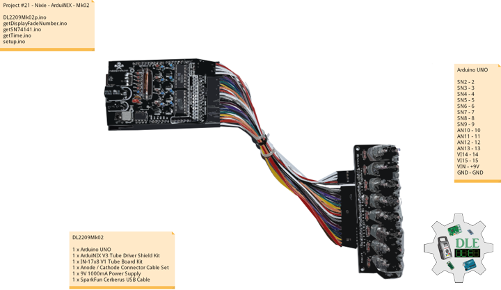
Arduino Mega 2560 R2
SN2 – 2
SN3 – 3
SN4 – 4
SN5 – 5
SN6 – 6
SN7 – 7
SN8 – 8
SN9 – 9
AN10 – 10
AN11 – 11
AN12 – 12
AN13 – 13
VI14 – 14
VI15 – 15
SDA – 20
SCL – 21
RO0 – 53
VIN – +3.3V
VIN – +5V
VIN – +9V
GND – GND
DL2209Mk03p.ino
/* ***** Don Luc Electronics © *****
Software Version Information
Project #21 - Nixie - DS3231 Precision RTC - Mk03
21-03
DL2209Mk03p.ino
1 x Arduino Mega 2560 R2
1 x ArduiNIX V3 Tube Driver Shield Kit
1 x IN-17x8 V1 Tube Board Kit
1 x Anode / Cathode Connector Cable Set
1 x DS3231 Precision RTC FeatherWing
1 x CR1220 12mm Coin Cell Battery
1 x Rocker Switch - SPST
1 x 10K Ohm
1 x 9V 1000mA Power Supply
1 x SparkFun Cerberus USB Cable
*/

// Include the Library Code
// Wire you to communicate with I2C/TWI devices
// Date and Time DS3231 RTC
#include "RTClib.h"

// SN74141 (1)
int ledPin_0_a = 2;
int ledPin_0_b = 3;
int ledPin_0_c = 4;
int ledPin_0_d = 5;

// SN74141 (2)
int ledPin_1_a = 6;
int ledPin_1_b = 7;
int ledPin_1_c = 8;
int ledPin_1_d = 9;

// Anode pins
int ledPin_a_1 = 10;
int ledPin_a_2 = 11;
int ledPin_a_3 = 12;
int ledPin_a_4 = 13;

// NOTE: Grounding on virtual pins 14 and 15
// (analog pins 0 and 1) will set the Hour and Mins.
int iVirtual14 = 14;
int iVirtual15 = 15;

// Fade
float fadeMax = 0.1f;
float fadeStep = 0.1f;
// Number Array
int NumberArray[8]={0,0,0,0,0,0,0,0};
int currNumberArray[8]={0,0,0,0,0,0,0,0};
float NumberArrayFadeInValue[8]={0.0f,0.0f,0.0f,0.0f,0.0f,0.0f,0.0f,0.0f};
float NumberArrayFadeOutValue[8]={5.0f,5.0f,5.0f,5.0f,5.0f,5.0f,5.0f,5.0f};

// Date and time functions using a DS3231 RTC
RTC_DS3231 RTC;

// Rocker Switch - SPST
int iRO0 = 53;
// State
int iRO0State = 0;

// Software Version Information
String sver = "21-03";

void loop() {

  // timeRTC
  timeRTC();

}
getDisplayFadeNumber.ino
// Display Fade Number
void DisplayFadeNumberString()
{

  // Anode channel 1 - numerals 0,4
  SetSN74141Chips(currNumberArray[0],currNumberArray[4]);
  digitalWrite(ledPin_a_1, HIGH);
  delay(NumberArrayFadeOutValue[0]);
  SetSN74141Chips(NumberArray[0],NumberArray[4]);
  delay(NumberArrayFadeInValue[0]);
  digitalWrite(ledPin_a_1, LOW);

  // Anode channel 2 - numerals 1,5
  SetSN74141Chips(currNumberArray[1],currNumberArray[5]);
  digitalWrite(ledPin_a_2, HIGH);
  delay(NumberArrayFadeOutValue[1]);
  SetSN74141Chips(NumberArray[1],NumberArray[5]);
  delay(NumberArrayFadeInValue[1]);
  digitalWrite(ledPin_a_2, LOW);

  // Anode channel 3 - numerals 2,6
  SetSN74141Chips(currNumberArray[2],currNumberArray[6]);
  digitalWrite(ledPin_a_3, HIGH);
  delay(NumberArrayFadeOutValue[2]);
  SetSN74141Chips(NumberArray[2],NumberArray[6]);
  delay(NumberArrayFadeInValue[2]);
  digitalWrite(ledPin_a_3, LOW);

  // Anode channel 4 - numerals 3,7
  SetSN74141Chips(currNumberArray[3],currNumberArray[7]);
  digitalWrite(ledPin_a_4, HIGH);
  delay(NumberArrayFadeOutValue[3]);
  SetSN74141Chips(NumberArray[3],NumberArray[7]);
  delay(NumberArrayFadeInValue[3]);
  digitalWrite(ledPin_a_4, LOW);

  // Loop thru and update all the arrays, and fades.
  for( int i = 0 ; i < 8 ; i ++ ) //equal to & of digits
  {
    if( NumberArray[i] != currNumberArray[i] )
    {
      NumberArrayFadeInValue[i] += fadeStep;
      NumberArrayFadeOutValue[i] -= fadeStep;

      if( NumberArrayFadeInValue[i] >= fadeMax )
      {
        NumberArrayFadeInValue[i] = 2.0f;
        NumberArrayFadeOutValue[i] = 4.0f; //affects the refresh cycle
        currNumberArray[i] = NumberArray[i];
      }
    }
  }

}
getRTCDS3231.ino
// DS3231 Precision RTC
// Setup RTC
void setupRTC() {

  // DS3231 Precision RTC
  RTC.begin();
  if (! RTC.begin() ) {
    while (1) delay(10);
  }

  if (RTC.lostPower()) {

    // Following line sets the RTC to the date & time this sketch was compiled
    RTC.adjust(DateTime(F(__DATE__), F(__TIME__)));
    // This line sets the RTC with an explicit date & time, for example to set
    // August 2, 2021 at 13:53:0 you would call:
    // RTC.adjust(DateTime(2022, 4, 26, 11, 39, 0));

  }

}
// timeRTC
void timeRTC() {

  // Date and Time
  DateTime now = RTC.now();

  // Read the state of the Switch value
  iRO0State = digitalRead(iRO0);

  // If it is the Switch State is HIGH
  if (iRO0State == HIGH) {


    // Get the high and low order values for hours, minute, seconds
    int lowerHours = now.hour() % 10;
    int upperHours = now.hour() - lowerHours;
    int lowerMins = now.minute() % 10;
    int upperMins = now.minute() - lowerMins;
    int lowerSeconds = now.second() % 10;
    int upperSeconds = now.second() - lowerSeconds;

    // 10 >= hours, minute, seconds
    if( upperSeconds >= 10 )   upperSeconds = upperSeconds / 10;
    if( upperMins >= 10 )      upperMins = upperMins / 10;
    if( upperHours >= 10 )     upperHours = upperHours / 10;
    if( upperHours == 0 && lowerHours == 0 )
    {

      upperHours = 1;
      lowerHours = 2;

    }

    // Fill in the Number array used to display on the Nixie tubes
    NumberArray[7] = upperHours;
    NumberArray[6] = lowerHours;
    NumberArray[5] = 0;
    NumberArray[4] = upperMins;
    NumberArray[3] = lowerMins;
    NumberArray[2] = 0;
    NumberArray[1] = upperSeconds;
    NumberArray[0] = lowerSeconds;

  } else {

    // Get the high and low order values for year, month, day
    int iYear = now.year() - 2000;
    int lowerYear = iYear % 10;
    int upperYear = iYear - lowerYear;
    int lowerMonth = now.month() % 10;
    int upperMonth = now.month() - lowerMonth;
    int lowerDay = now.day() % 10;
    int upperDay = now.day() - lowerDay;

    // 10 >= year, month, day
    if( upperDay >= 10 )   upperDay = upperDay / 10;
    if( upperMonth >= 10 )      upperMonth = upperMonth / 10;
    if( upperYear >= 10 )     upperYear = upperYear / 10;

    // Fill in the Number array used to display on the Nixie tubes
    NumberArray[7] = 2;
    NumberArray[6] = 0;
    NumberArray[5] = upperYear;
    NumberArray[4] = lowerYear;
    NumberArray[3] = upperMonth;
    NumberArray[2] = lowerMonth;
    NumberArray[1] = upperDay;
    NumberArray[0] = lowerDay;

  }

  // Display
  DisplayFadeNumberString();

}
getSN74141.ino
// SN74141
// SN74141 : Truth Table
//D C B A #
//L,L,L,L 0
//L,L,L,H 1
//L,L,H,L 2
//L,L,H,H 3
//L,H,L,L 4
//L,H,L,H 5
//L,H,H,L 6
//L,H,H,H 7
//H,L,L,L 8
//H,L,L,H 9
// isSetupSN74141
void isSetupSN74141(){

  pinMode(ledPin_0_a, OUTPUT);
  pinMode(ledPin_0_b, OUTPUT);
  pinMode(ledPin_0_c, OUTPUT);
  pinMode(ledPin_0_d, OUTPUT);

  pinMode(ledPin_1_a, OUTPUT);
  pinMode(ledPin_1_b, OUTPUT);
  pinMode(ledPin_1_c, OUTPUT);
  pinMode(ledPin_1_d, OUTPUT);

  pinMode(ledPin_a_1, OUTPUT);
  pinMode(ledPin_a_2, OUTPUT);
  pinMode(ledPin_a_3, OUTPUT);
  pinMode(ledPin_a_4, OUTPUT);

  // NOTE: Grounding on virtual pins 14 and 15
  // (analog pins 0 and 1) will set the Hour and Mins.
  // Set the vertual pin 14 (pin 0 on the analog inputs )
  pinMode( iVirtual14, INPUT );
  // Set pin 14 as a pull up resistor.
  digitalWrite(iVirtual14, HIGH);
  // Set the vertual pin 15 (pin 1 on the analog inputs )
  pinMode( iVirtual15, INPUT );
  // Set pin 15 as a pull up resistor.
  digitalWrite(iVirtual15, HIGH);

}
// SetSN74141Chips
void SetSN74141Chips( int num2, int num1 )
{

  // Set defaults
  // Will display a zero.
  int a = 0;
  int b = 0;
  int c = 0;
  int d = 0;

  // Load the a,b,c,d.. to send to the SN74141 IC (1)
  switch( num1 )
  {
    case 0:
      a=0;
      b=0;
      c=0;
      d=0;
      break;
    case 1:
      a=1;
      b=0;
      c=0;
      d=0;
      break;
    case 2:
      a=0;
      b=1;
      c=0;
      d=0;
      break;
    case 3:
      a=1;
      b=1;
      c=0;
      d=0;
      break;
    case 4:
      a=0;
      b=0;
      c=1;
      d=0;
      break;
    case 5:
      a=1;
      b=0;
      c=1;
      d=0;
      break;
    case 6:
      a=0;
      b=1;
      c=1;
      d=0;
      break;
    case 7:
      a=1;
      b=1;
      c=1;
      d=0;
      break;
    case 8:
      a=0;
      b=0;
      c=0;
      d=1;
      break;
    case 9:
      a=1;
      b=0;
      c=0;
      d=1;
      break;
    default:
      a=1;
      b=1;
      c=1;
      d=1;
      break;
  }

  // Write to output pins.
  digitalWrite(ledPin_0_d, d);
  digitalWrite(ledPin_0_c, c);
  digitalWrite(ledPin_0_b, b);
  digitalWrite(ledPin_0_a, a);

  // Load the a,b,c,d.. to send to the SN74141 IC (2)
  switch( num2 )
  {
    case 0:
      a=0;
      b=0;
      c=0;
      d=0;
      break;
    case 1:
      a=1;
      b=0;
      c=0;
      d=0;
      break;
    case 2:
      a=0;
      b=1;
      c=0;
      d=0;
      break;
    case 3:
      a=1;
      b=1;
      c=0;
      d=0;
      break;
    case 4:
      a=0;
      b=0;
      c=1;
      d=0;
      break;
    case 5:
      a=1;
      b=0;
      c=1;
      d=0;
      break;
    case 6:
      a=0;
      b=1;
      c=1;
      d=0;
      break;
    case 7:
      a=1;
      b=1;
      c=1;
      d=0;
      break;
    case 8:
      a=0;
      b=0;
      c=0;
      d=1;
      break;
    case 9:
      a=1;
      b=0;
      c=0;
      d=1;
      break;
    default:
      a=1;
      b=1;
      c=1;
      d=1;
      break;
  }

  // Write to output pins
  digitalWrite(ledPin_1_d, d);
  digitalWrite(ledPin_1_c, c);
  digitalWrite(ledPin_1_b, b);
  digitalWrite(ledPin_1_a, a);

}
setup.ino
// Setup
void setup() {

  // isSetupSN74141
  isSetupSN74141();

  // Switch
  pinMode(iRO0, INPUT);

  // Setup RTC
  setupRTC();

}
——
People can contact us: https://www.donluc.com/?page_id=1927
Technology Experience
- Single-Board Microcontrollers (PIC, Arduino, Raspberry Pi,Espressif, etc…)
- IoT
- Robotics
- Camera and Video Capture Receiver Stationary, Wheel/Tank and Underwater Vehicle
- Unmanned Vehicles Terrestrial and Marine
- Research & Development (R & D)
Instructor and E-Mentor
- IoT
- PIC Microcontrollers
- Arduino
- Raspberry Pi
- Espressif
- Robotics
Follow Us
J. Luc Paquin – Curriculum Vitae – 2022 English & Español
https://www.jlpconsultants.com/luc/
Web: https://www.donluc.com/
Web: https://www.jlpconsultants.com/
Facebook: https://www.facebook.com/neosteam.labs.9/
YouTube: https://www.youtube.com/channel/UC5eRjrGn1CqkkGfZy0jxEdA
Twitter: https://twitter.com/labs_steam
Pinterest: https://www.pinterest.com/NeoSteamLabs/
Instagram: https://www.instagram.com/neosteamlabs/
Don Luc