——
#DonLucElectronics #DonLuc #Synthesizer #Mozzi #Keyboard #ADSREnvelope #Arduino #SparkFunRedBoard #Project #Fritzing #Programming #Electronics #Microcontrollers #Consultant
——
——
——
——
4 Stages of an ADSR Envelope
An ADSR envelope features these four stages.
- 1 Attack: The attack phase begins the moment a key is pressed. This phase determines how quickly a sound reaches full volume before entering the decay phase. On an analog synthesizer, this phase is typically instantaneous. Some modern synthesizers allow for the attack time to be delayed.
- 2 Decay: The decay phase determines the length of the drop from the peak level to the sustain level of a sound. The decay time can often be altered to change the overall sound. For instance, a short attack and a long decay will produce a sound that reaches maximum amplitude quickly and falls slowly to the sustain level.
- 3 Sustain: The sustain phase does not specify a length of time. Instead, it determines the volume of a sound for the entire hold time between the decay and release phases.
- 4 Release: The final phase determines the speed at which a sound ends from the moment you release the key. Depending on the desired sound, the release time can be short or long.
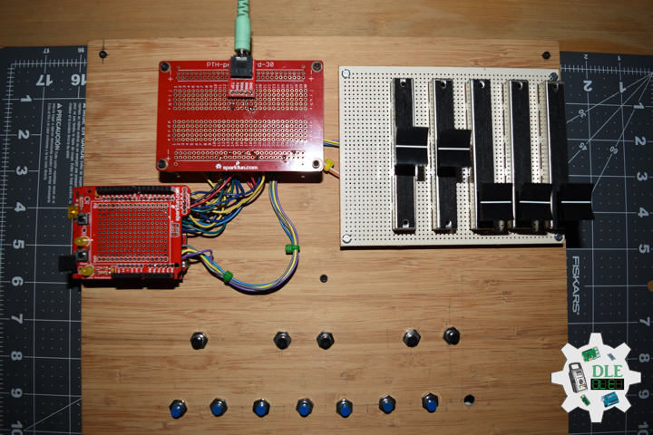
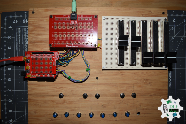
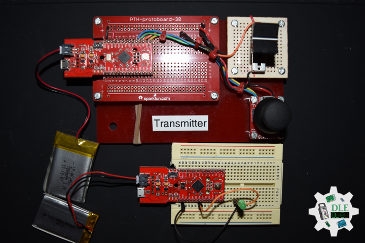
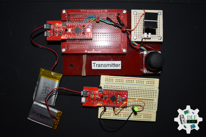
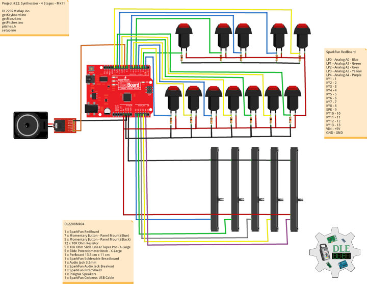
DL2208Mk04
1 x SparkFun RedBoard
7 x Momentary Button – Panel Mount (Blue)
5 x Momentary Button – Panel Mount (Black)
12 x 10K Ohm Resistor
5 x 10k Ohm Slide Linear Taper Pot – X-Large
5 x Slide Potentiometer Knob – X-Large
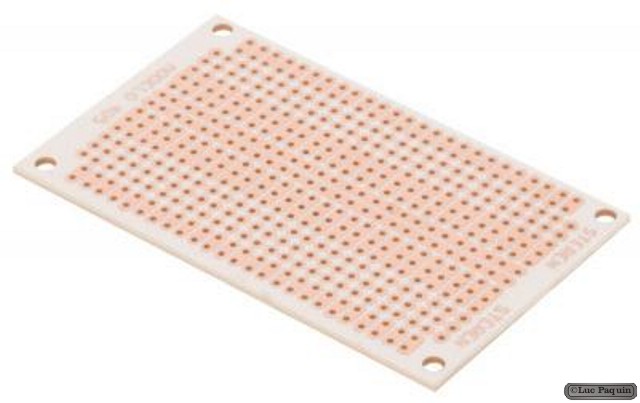
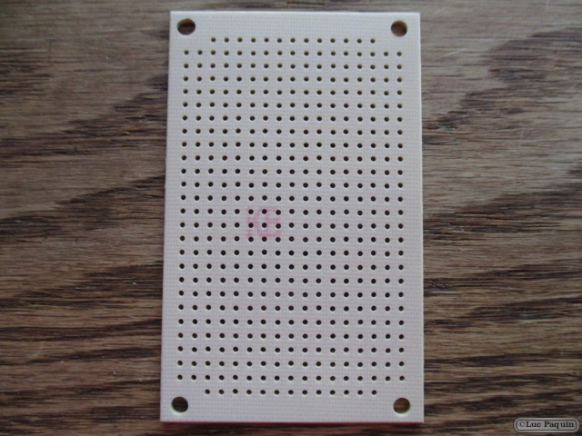
1 x Perfboard 13.5 cm x 11 cm
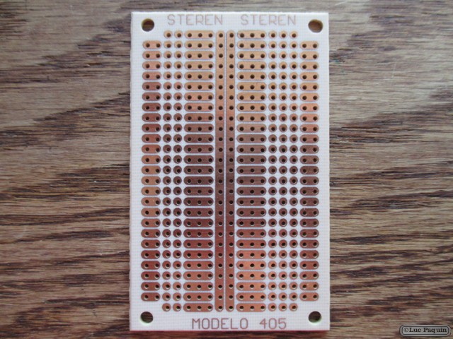
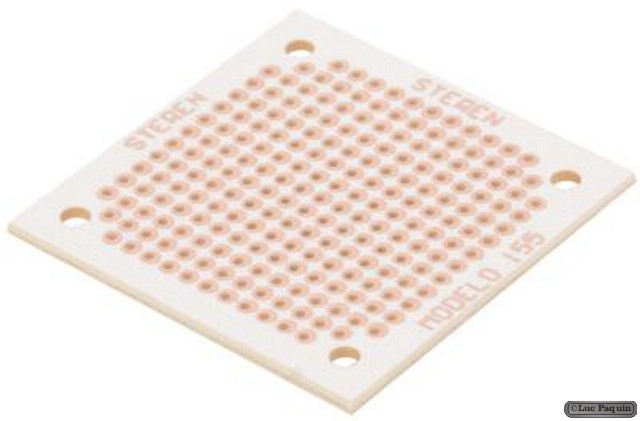
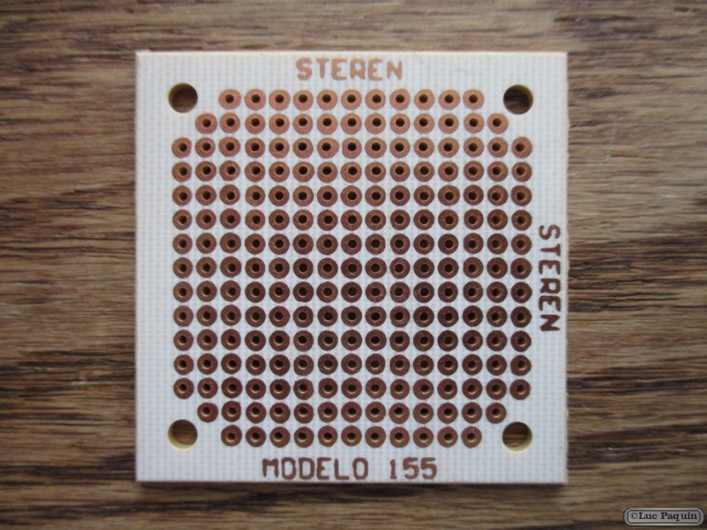
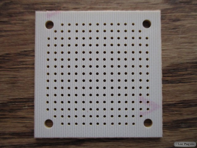
1 x SparkFun Solderable Breadboard
1 x Audio Jack 3.5mm
1 x SparkFun Audio Jack Breakout
1 x SparkFun ProtoShield
1 x Insignia Speakers
1 x SparkFun Cerberus USB Cable
SparkFun RedBoard
LP0 – Analog A0 – Blue
LP1 – Analog A1 – Green
LP2 – Analog A2 – Grey
LP3 – Analog A3 – Yellow
LP4 – Analog A4 – Purple
KY1 – 1
KY2 – 2
KY3 – 3
KY4 – 4
KY5 – 5
KY6 – 6
KY7 – 7
KY8 – 8
SPK – 9
KY10 – 10
KY11 – 11
KY12 – 12
KY13 – 13
VIN – +5V
GND – GND
DL2208Mk04p.ino
/* ***** Don Luc Electronics © *****
Software Version Information
Project #22: Synthesizer - 4 Stages - Mk11
22-11
DL2208Mk04p.ino
1 x SparkFun RedBoard
7 x Momentary Button - Panel Mount (Blue)
5 x Momentary Button - Panel Mount (Black)
12 x 1K Ohm Resistor
5 x 10k Ohm Slide Linear Taper Pot - X-Large
5 x Slide Potentiometer Knob - X-Large
1 x Perfboard 13.5 cm x 11 cm
1 x SparkFun Solderable Breadboard
1 x Audio Jack 3.5mm
1 x SparkFun Audio Jack Breakout
1 x SparkFun ProtoShield
1 x Insignia Speakers
1 x SparkFun Cerberus USB Cable
*/

// Include the Library Code
// Pitches
#include "pitches.h"
// Mozzi
#include <MozziGuts.h>
// Oscillator
#include <Oscil.h>
// Sine Wave Table For Oscillator
#include <tables/sin2048_int8.h>
// ADSR envelope generator
#include <ADSR.h>

// Simple Keyboard
// Minimum reading of the button that generates a note
const int iKeyboard1 = 1;
const int iKeyboard2 = 2;
const int iKeyboard3 = 3;
const int iKeyboard4 = 4;
const int iKeyboard5 = 5;
const int iKeyboard6 = 6;
const int iKeyboard7 = 7;
const int iKeyboard8 = 8;
const int iKeyboard10 = 10;
const int iKeyboard11 = 11;
const int iKeyboard12 = 12;
const int iKeyboard13 = 13;
// Button is pressed
int iB1 = 1;
int iB2 = 1;
int iB3 = 1;
int iB4 = 1;
int iB5 = 1;
int iB6 = 1;
int iB7 = 1;
int iB8 = 1;
int iB10 = 1;
int iB11 = 1;
int iB12 = 1;
int iB13 = 1;

// Set the input for the potentiometer for Frequency to analog pin 2
const int potFreq = A2;
int iFreg = 1;
int iNoteA = 0;
int iNoteAS = 0;
int iNoteB = 0;
int iNoteC = 0;
int iNoteCS = 0;
int iNoteD = 0;
int iNoteDS = 0;
int iNoteE = 0;
int iNoteF = 0;
int iNoteFS = 0;
int iNoteG = 0;
int iNoteGS = 0;

// Potentiometer
int iPot3 = A3;
int iPot4 = A4;

//Oscillator Functions declared for output envelope 1
// Sine Wave
Oscil <2048, AUDIO_RATE> aSin1(SIN2048_DATA);

// ADSR declaration/definition
// Comment out to use control rate of 128
#define CONTROL_RATE 128
ADSR <CONTROL_RATE, CONTROL_RATE> envelope1;

// Set the input for the potentiometer Attack to analog pin 1
const int potAttack = A0;
// Attack
int attack_level = 0;
int iAttack = 0;

// Set the input for the potentiometer for Decay to analog pin 2
const int potDecay = A1;
// Decay
int decay_level = 0;
int iDecay = 0;

// Software Version Information
String sver = "22-11";

void loop() {

  // Audio Hook
  audioHook();

}
getKeyboard.ino
// getKeyboard
// setupKeyboard
void setupKeyboard() {

  // Initialize the button pin as an input
  pinMode(iKeyboard1, INPUT_PULLUP);
  pinMode(iKeyboard2, INPUT_PULLUP);
  pinMode(iKeyboard3, INPUT_PULLUP);
  pinMode(iKeyboard4, INPUT_PULLUP);
  pinMode(iKeyboard5, INPUT_PULLUP);
  pinMode(iKeyboard6, INPUT_PULLUP);
  pinMode(iKeyboard7, INPUT_PULLUP);
  pinMode(iKeyboard8, INPUT_PULLUP);
  pinMode(iKeyboard10, INPUT_PULLUP);
  pinMode(iKeyboard11, INPUT_PULLUP);
  pinMode(iKeyboard12, INPUT_PULLUP);
  pinMode(iKeyboard13, INPUT_PULLUP);

}
// isKeyboard
void isKeyboard() {

  // Choose envelope levels
  // attack_level
  iAttack = mozziAnalogRead( potAttack );
  attack_level = map( iAttack, 0, 1023, 100, 400);
  // Attack Level
  envelope1.setAttackLevel( attack_level );
  // decay_level
  iDecay = mozziAnalogRead( potDecay );
  decay_level = map( iDecay, 0, 1023, 50, 255);
  // Decay Level
  envelope1.setDecayLevel( decay_level );

  // Read the state of the button value 1
  if ( digitalRead(iKeyboard1) == HIGH ) {

    // Button is pressed - pullup keeps pin high normally 1
    iB1 = iB1 + 1;
    // ADSR declaration/definition
    envelope1.noteOn();
    aSin1.setFreq(iNoteA);

  }
  else
  {

    iB1 = iB1 - 1;

  }

  // Read the state of the button value 2
  if ( digitalRead(iKeyboard2) == HIGH ) {

    // Button is pressed - pullup keeps pin high normally 2
    iB2 = iB2 + 1;
    // ADSR declaration/definition
    envelope1.noteOn();
    aSin1.setFreq(iNoteAS);

  }
  else
  {

    iB2 = iB2 - 1;

  }

  // Read the state of the button value 3
  if ( digitalRead(iKeyboard3) == HIGH ) {

    // Button is pressed - pullup keeps pin high normally 3
    iB3 = iB3 + 1;
    // ADSR declaration/definition
    envelope1.noteOn();
    aSin1.setFreq(iNoteB);

  }
  else
  {

    iB3 = iB3 - 1;

  }

  // Read the state of the button value 4
  if ( digitalRead(iKeyboard4) == HIGH ) {

    // Button is pressed - pullup keeps pin high normally 4
    iB4 = iB4 + 1;
    // ADSR declaration/definition
    envelope1.noteOn();
    aSin1.setFreq(iNoteC);

  }
  else
  {

    iB4 = iB4 - 1;

  }

  // Read the state of the button value 5
  if ( digitalRead(iKeyboard5) == HIGH ) {

    // Button is pressed - pullup keeps pin high normally 5
    iB5 = iB5 + 1;
    // ADSR declaration/definition
    envelope1.noteOn();
    aSin1.setFreq(iNoteCS);

  }
  else
  {

    iB5 = iB5 - 1;

  }

  // Read the state of the button value 6
  if ( digitalRead(iKeyboard6) == HIGH ) {

    // Button is pressed - pullup keeps pin high normally 6
    iB6 = iB6 + 1;
    // ADSR declaration/definition
    envelope1.noteOn();
    aSin1.setFreq(iNoteD);

  }
  else
  {

    iB6 = iB6 - 1;

  }

  // Read the state of the button value 7
  if ( digitalRead(iKeyboard7) == HIGH ) {

    // Button is pressed - pullup keeps pin high normally 7
    iB7 = iB7 + 1;
    // ADSR declaration/definition
    envelope1.noteOn();
    aSin1.setFreq(iNoteDS);

  }
  else
  {

    iB7 = iB7 - 1;

  }

  // Read the state of the button value 8
  if ( digitalRead(iKeyboard8) == HIGH ) {

    // Button is pressed - pullup keeps pin high normally 8
    iB8 = iB8 + 1;
    // ADSR declaration/definition
    envelope1.noteOn();
    aSin1.setFreq(iNoteE);

  }
  else
  {

    iB8 = iB8 - 1;

  }

  // Read the state of the button value 10
  if ( digitalRead(iKeyboard10) == HIGH ) {

    // Button is pressed - pullup keeps pin high normally 10
    iB10 = iB10 + 1;
    // ADSR declaration/definition
    envelope1.noteOn();
    aSin1.setFreq(iNoteF);

  }
  else
  {

    iB10 = iB10 - 1;

  }

  // Read the state of the button value 11
  if ( digitalRead(iKeyboard11) == HIGH ) {

    // Button is pressed - pullup keeps pin high normally 11
    iB11 = iB11 + 1;
    // ADSR declaration/definition
    envelope1.noteOn();
    aSin1.setFreq(iNoteFS);

  }
  else
  {

    iB11 = iB11 - 1;

  }

  // Read the state of the button value 12
  if ( digitalRead(iKeyboard12) == HIGH ) {

    // Button is pressed - pullup keeps pin high normally 12
    iB12 = iB12 + 1;
    // ADSR declaration/definition
    envelope1.noteOn();
    aSin1.setFreq(iNoteG);

  }
  else
  {

    iB12 = iB12 - 1;

  }

  // Read the state of the button value 13
  if ( digitalRead(iKeyboard13) == HIGH ) {

    // Button is pressed - pullup keeps pin high normally 13
    iB13 = iB13 + 1;
    // ADSR declaration/definition
    envelope1.noteOn();
    aSin1.setFreq(iNoteGS);

  }
  else
  {

    iB13 = iB13 - 1;

  }

}
getMozzi.ino
// Mozzi
// Update Control
void updateControl(){

  // Frequency
  isPitches();

  // Keyboard
  isKeyboard();

}
// Update Audio
int updateAudio()
{

  // Update Audio
  // ADSR declaration/definition
  envelope1.update();
  // >>8 for AUDIO_MODE STANDARD
  return (int) (envelope1.next() * aSin1.next())>>8;

}
getPitches.ino
// Pitches
// isPitches
void isPitches(){

  // Frequency
  // Value is 0-1023
  iFreg = mozziAnalogRead(potFreq);
  iFreg = map(iFreg, 0, 1023, 2, 6);

  // Range Frequency Note Low => High
  switch ( iFreg ) {
    case 1:
      // NOTE A1
      iNoteA = NOTE_A1;
      iNoteAS = NOTE_AS1;
      iNoteB = NOTE_B1;
      iNoteC = NOTE_C2;
      iNoteCS = NOTE_CS2;
      iNoteD = NOTE_D2;
      iNoteDS = NOTE_DS2;
      iNoteE = NOTE_E2;
      iNoteF = NOTE_F2;
      iNoteFS = NOTE_FS2;
      iNoteG = NOTE_G2;
      iNoteGS = NOTE_GS2;
      break;
    case 2:
      // NOTE A2
      iNoteA = NOTE_A2;
      iNoteAS = NOTE_AS2;
      iNoteB = NOTE_B2;
      iNoteC = NOTE_C3;
      iNoteCS = NOTE_CS3;
      iNoteD = NOTE_D3;
      iNoteDS = NOTE_DS3;
      iNoteE = NOTE_E3;
      iNoteF = NOTE_F3;
      iNoteFS = NOTE_FS3;
      iNoteG = NOTE_G3;
      iNoteGS = NOTE_GS3;
      break;
    case 3:
      // NOTE A3
      iNoteA = NOTE_A3;
      iNoteAS = NOTE_AS3;
      iNoteB = NOTE_B3;
      iNoteC = NOTE_C4;
      iNoteD = NOTE_D4;
      iNoteDS = NOTE_DS4;
      iNoteE = NOTE_E4;
      iNoteF = NOTE_F4;
      iNoteFS = NOTE_FS4;
      iNoteG = NOTE_G4;
      iNoteGS = NOTE_GS4;
      break;
    case 4:
      // NOTE A4
      iNoteA = NOTE_A4;
      iNoteAS = NOTE_AS4;
      iNoteB = NOTE_B4;
      iNoteC = NOTE_C5;
      iNoteCS = NOTE_CS5;
      iNoteD = NOTE_D5;
      iNoteE = NOTE_E5;
      iNoteF = NOTE_F5;
      iNoteFS = NOTE_FS5;
      iNoteG = NOTE_G5;
      iNoteGS = NOTE_GS5;
      break;
    case 5:
      // NOTE A5
      iNoteA = NOTE_A5;
      iNoteAS = NOTE_AS5;
      iNoteB = NOTE_B5;
      iNoteC = NOTE_C6;
      iNoteCS = NOTE_CS6;
      iNoteD = NOTE_D6;
      iNoteDS = NOTE_DS6;
      iNoteE = NOTE_E6;
      iNoteF = NOTE_F6;
      iNoteFS = NOTE_FS6;
      iNoteG = NOTE_G6;
      iNoteGS = NOTE_GS6;
      break;
    case 6:
      // NOTE A6
      iNoteA = NOTE_A6;
      iNoteAS = NOTE_AS6;
      iNoteB = NOTE_B6;
      iNoteC = NOTE_C7;
      iNoteCS = NOTE_CS7;
      iNoteD = NOTE_D7;
      iNoteDS = NOTE_DS7;
      iNoteE = NOTE_E7;
      iNoteF = NOTE_F7;
      iNoteFS = NOTE_FS7;
      iNoteG = NOTE_G7;
      iNoteGS = NOTE_GS7;
      break;
  }

}
pitches.h
/*****************************************************************
 * Pitches NOTE_B0 <=> NOTE_DS8 - NOTE_A4 is "A" measured at 440Hz
 *****************************************************************/

#define NOTE_B0  31
#define NOTE_C1  33
#define NOTE_CS1  35
#define NOTE_D1  37
#define NOTE_DS1  39
#define NOTE_E1  41
#define NOTE_F1  44
#define NOTE_FS1  46
#define NOTE_G1  49
#define NOTE_GS1  52
#define NOTE_A1  55
#define NOTE_AS1  58
#define NOTE_B1  62
#define NOTE_C2  65
#define NOTE_CS2  69
#define NOTE_D2  73
#define NOTE_DS2  78
#define NOTE_E2  82
#define NOTE_F2  87
#define NOTE_FS2  93
#define NOTE_G2  98
#define NOTE_GS2  104
#define NOTE_A2  110
#define NOTE_AS2  117
#define NOTE_B2  123
#define NOTE_C3  131
#define NOTE_CS3  139
#define NOTE_D3  147
#define NOTE_DS3  156
#define NOTE_E3  165
#define NOTE_F3  175
#define NOTE_FS3 185
#define NOTE_G3  196
#define NOTE_GS3  208
#define NOTE_A3  220
#define NOTE_AS3  233
#define NOTE_B3  247
#define NOTE_C4  262
#define NOTE_CS4  277
#define NOTE_D4  294
#define NOTE_DS4 311
#define NOTE_E4  330
#define NOTE_F4  349
#define NOTE_FS4  370
#define NOTE_G4  392
#define NOTE_GS4  415
#define NOTE_A4  440
#define NOTE_AS4  466
#define NOTE_B4  494
#define NOTE_C5  523
#define NOTE_CS5  554
#define NOTE_D5  587
#define NOTE_DS5  622
#define NOTE_E5  659
#define NOTE_F5  698
#define NOTE_FS5  740
#define NOTE_G5  784
#define NOTE_GS5  831
#define NOTE_A5  880
#define NOTE_AS5  932
#define NOTE_B5  988
#define NOTE_C6  1047
#define NOTE_CS6  1109
#define NOTE_D6  1175
#define NOTE_DS6  1245
#define NOTE_E6  1319
#define NOTE_F6  1397
#define NOTE_FS6  1480
#define NOTE_G6  1568
#define NOTE_GS6  1661
#define NOTE_A6  1760
#define NOTE_AS6  1865
#define NOTE_B6  1976
#define NOTE_C7  2093
#define NOTE_CS7  2217
#define NOTE_D7  2349
#define NOTE_DS7  2489
#define NOTE_E7  2637
#define NOTE_F7  2794
#define NOTE_FS7  2960
#define NOTE_G7  3136
#define NOTE_GS7  3322
#define NOTE_A7  3520
#define NOTE_AS7  3729
#define NOTE_B7  3951
#define NOTE_C8  4186
#define NOTE_CS8  4435
#define NOTE_D8  4699
#define NOTE_DS8  4978
setup.ino
// Setup
void setup() {

  // Setup Keyboard
  setupKeyboard();

  // Mozzi Start
  startMozzi( CONTROL_RATE );
  // Sets Attack and Decay Levels; assumes Sustain, Decay, and Idle times
  envelope1.setADLevels(200,200);
  // Sets Decay time in milliseconds
  envelope1.setDecayTime(200);
  // Sustain Time setting for envelope1
  envelope1.setSustainTime(52500);

}
——
People can contact us: https://www.donluc.com/?page_id=1927
Technology Experience
- Single-Board Microcontrollers (PIC, Arduino, Raspberry Pi,Espressif, etc…)
- IoT
- Robotics
- Camera and Video Capture Receiver Stationary, Wheel/Tank and Underwater Vehicle
- Unmanned Vehicles Terrestrial and Marine
- Research & Development (R & D)
Instructor and E-Mentor
- IoT
- PIC Microcontrollers
- Arduino
- Raspberry Pi
- Espressif
- Robotics
Follow Us
J. Luc Paquin – Curriculum Vitae – 2022 English & Español
https://www.jlpconsultants.com/luc/
Web: https://www.donluc.com/
Web: https://www.jlpconsultants.com/
Facebook: https://www.facebook.com/neosteam.labs.9/
YouTube: https://www.youtube.com/channel/UC5eRjrGn1CqkkGfZy0jxEdA
Twitter: https://twitter.com/labs_steam
Pinterest: https://www.pinterest.com/NeoSteamLabs/
Instagram: https://www.instagram.com/neosteamlabs/
Don Luc