——
#DonLucElectronics #DonLuc #Synthesizer #Mozzi #Keyboard #ADSREnvelope #Arduino #SparkFunRedBoard #Project #Fritzing #Programming #Electronics #Microcontrollers #Consultant
——
——
——
——
Gain
Gain is the process of managing the relative levels in each step of an audio signal flow to prevent introduction of noise and distortion, particularly in the analogue realm. Ideal gain occurs when each component in an audio signal flow is receiving and transmitting signal in the optimum region of its dynamic range.
Before we can effectively compare these two properties of audio, we need to make sure we understand what each is separately. Keep in mind that both modulate the amplitude of a signal, which translates into a change in loudness. It gets more complicated, dealing with voltage and current in electronics. Amplitude is measured in voltage, which is a direct corollary to volume. In plain language, gain is kind of like an amplitude knob at the input of a piece of hardware or software that controls the loudness before it goes through the circuitry.
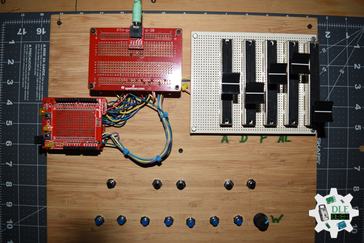
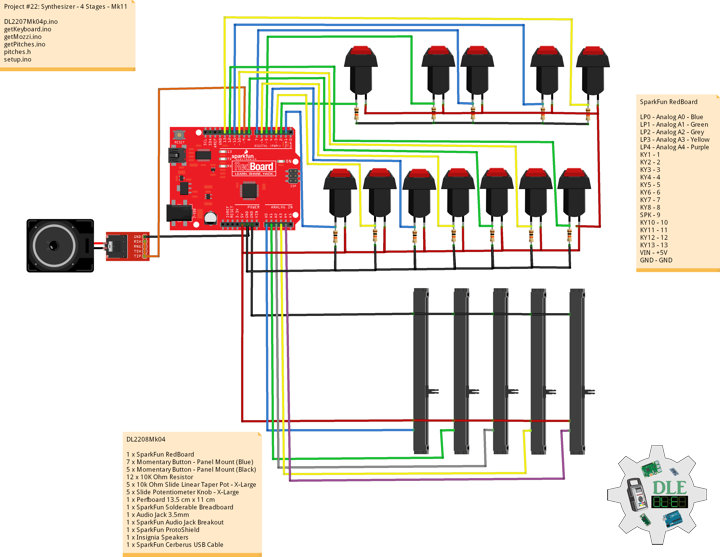
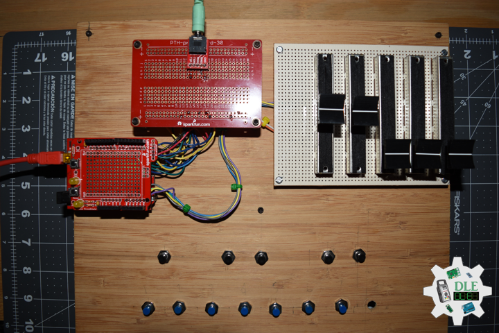
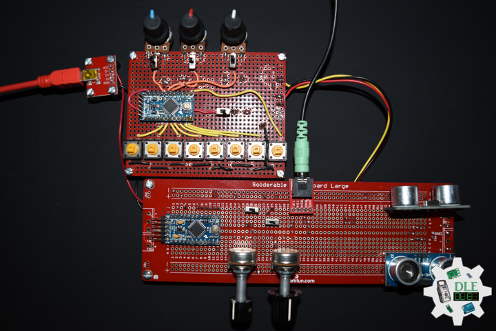
DL2208Mk07
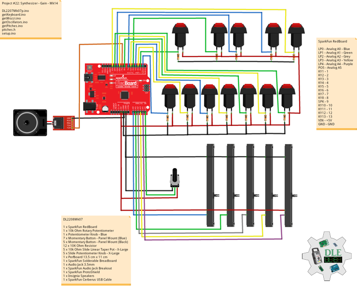
1 x SparkFun RedBoard
1 x 10k Ohm Rotary Potentiometer
1 x Potentiometer Knob – Blue
7 x Momentary Button – Panel Mount (Blue)
5 x Momentary Button – Panel Mount (Black)
12 x 10K Ohm Resistor
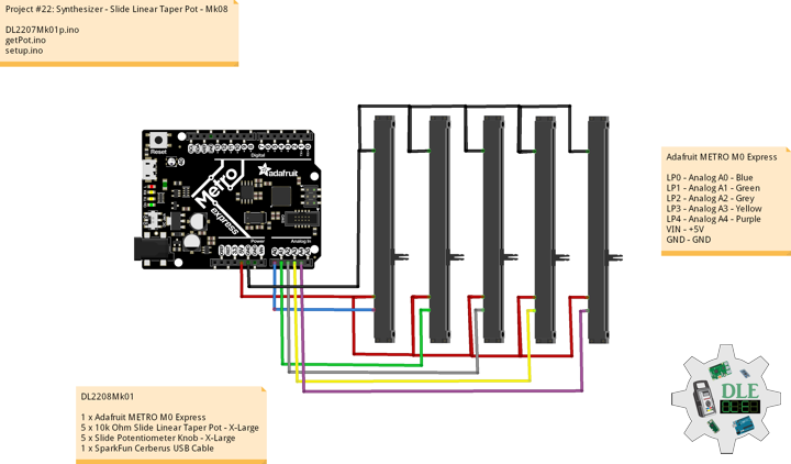
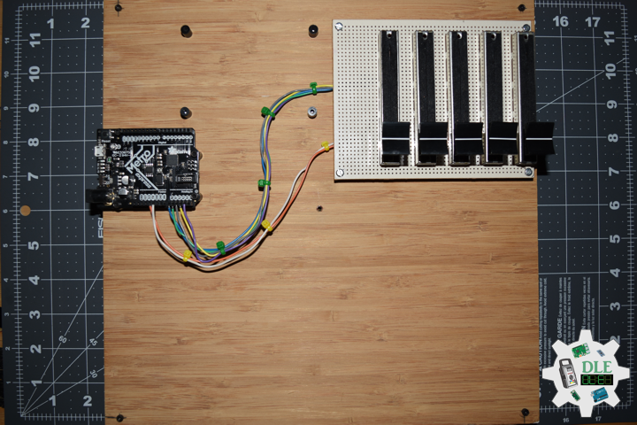
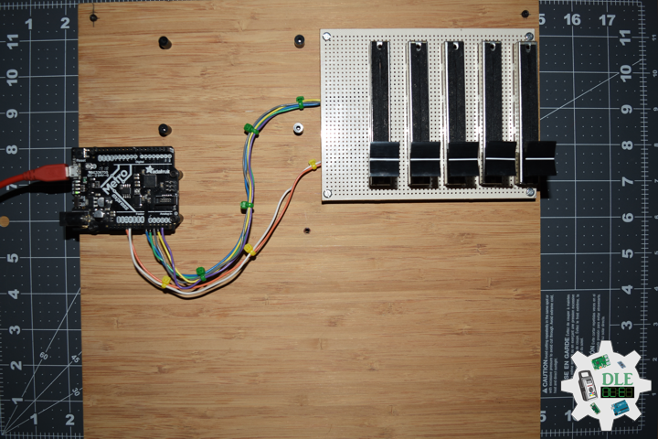
5 x 10k Ohm Slide Linear Taper Pot – X-Large
5 x Slide Potentiometer Knob – X-Large
1 x Perfboard 13.5 cm x 11 cm
1 x SparkFun Solderable Breadboard
1 x Audio Jack 3.5mm
1 x SparkFun Audio Jack Breakout
1 x SparkFun ProtoShield
1 x Insignia Speakers
1 x SparkFun Cerberus USB Cable
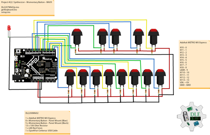
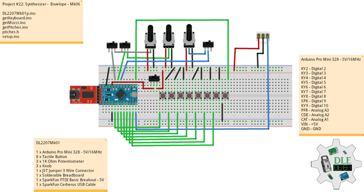
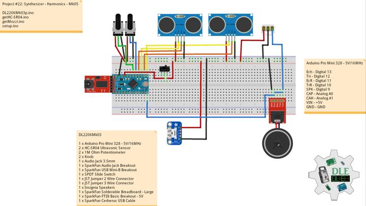
SparkFun RedBoard
LP0 – Analog A0 – Blue
LP1 – Analog A1 – Green
LP2 – Analog A2 – Grey
LP3 – Analog A3 – Yellow
LP4 – Analog A4 – Purple
PO5 – Analog A5
KY1 – 1
KY2 – 2
KY3 – 3
KY4 – 4
KY5 – 5
KY6 – 6
KY7 – 7
KY8 – 8
SPK – 9
KY10 – 10
KY11 – 11
KY12 – 12
KY13 – 13
VIN – +5V
GND – GND
——
DL2208Mk07p.ino
/* ***** Don Luc Electronics © *****
Software Version Information
Project #22: Synthesizer - Gain - Mk14
22-14
DL2208Mk07p.ino
1 x SparkFun RedBoard
1 x 10k Ohm Rotary Potentiometer
1 x Potentiometer Knob - Blue
7 x Momentary Button - Panel Mount (Blue)
5 x Momentary Button - Panel Mount (Black)
12 x 1K Ohm Resistor
5 x 10k Ohm Slide Linear Taper Pot - X-Large
5 x Slide Potentiometer Knob - X-Large
1 x Perfboard 13.5 cm x 11 cm
1 x SparkFun Solderable Breadboard
1 x Audio Jack 3.5mm
1 x SparkFun Audio Jack Breakout
1 x SparkFun ProtoShield
1 x Insignia Speakers
1 x SparkFun Cerberus USB Cable
*/

// Include the Library Code
// Pitches
#include "pitches.h"
// Mozzi
#include <MozziGuts.h>
// Oscillator
#include <Oscil.h>
// Sine Wave Table For Oscillator
#include <tables/sin2048_int8.h>
// Cosine Wave Table For Oscillator
#include <tables/cos2048_int8.h>
// Sawtooth Wave Table For Oscillator
#include <tables/saw2048_int8.h>
// Triangle Wave Table For Oscillator
#include <tables/triangle2048_int8.h>
// Square Wave Table For Oscillator
#include <tables/square_no_alias_2048_int8.h>
// ADSR envelope generator
#include <ADSR.h>

// Simple Keyboard
// Minimum reading of the button that generates a note
const int iKeyboard1 = 1;
const int iKeyboard2 = 2;
const int iKeyboard3 = 3;
const int iKeyboard4 = 4;
const int iKeyboard5 = 5;
const int iKeyboard6 = 6;
const int iKeyboard7 = 7;
const int iKeyboard8 = 8;
const int iKeyboard10 = 10;
const int iKeyboard11 = 11;
const int iKeyboard12 = 12;
const int iKeyboard13 = 13;
// Button is pressed
int iB1 = 1;
int iB2 = 1;
int iB3 = 1;
int iB4 = 1;
int iB5 = 1;
int iB6 = 1;
int iB7 = 1;
int iB8 = 1;
int iB10 = 1;
int iB11 = 1;
int iB12 = 1;
int iB13 = 1;

// Set the input for the potentiometer for Frequency to analog pin 2
const int potFreq = A2;
int iFreg = 1;
int iNoteA = 0;
int iNoteAS = 0;
int iNoteB = 0;
int iNoteC = 0;
int iNoteCS = 0;
int iNoteD = 0;
int iNoteDS = 0;
int iNoteE = 0;
int iNoteF = 0;
int iNoteFS = 0;
int iNoteG = 0;
int iNoteGS = 0;

// Gain
const int iGainPot4 = A4;
// Control variable, use the smallest data size you can for anything used in audio
byte gain = 0;
int iGain = 0;

//Oscillator Functions declared for output envelope 1
// Carrier
Oscil<COS2048_NUM_CELLS, AUDIO_RATE> aCarrier;
// Set the input for the potentiometer for Oscillator to analog pin 4
const int potWave = A5;
// Wave
int iWave;
int iWaveLevel;

// ADSR declaration/definition
// Comment out to use control rate of 128
#define CONTROL_RATE 128
ADSR <CONTROL_RATE, CONTROL_RATE> envelope1;

// Set the input for the potentiometer Attack to analog pin 1
const int potAttack = A0;
// Attack
int attack_level = 0;
int iAttack = 0;

// Set the input for the potentiometer for Decay to analog pin 2
const int potDecay = A1;
// Decay
int decay_level = 0;
int iDecay = 0;

// Set the input for the potentiometer Attack Time to analog pin 3
const int potAttackTime = A3;
// Attack Time
int AttackTime_level = 0;
int iAttackTime = 0;

// Software Version Information
String sver = "22-14";

void loop() {

  // Audio Hook
  audioHook();

}
getKeyboard.ino
// getKeyboard
// setupKeyboard
void setupKeyboard() {

  // Initialize the button pin as an input
  pinMode(iKeyboard1, INPUT_PULLUP);
  pinMode(iKeyboard2, INPUT_PULLUP);
  pinMode(iKeyboard3, INPUT_PULLUP);
  pinMode(iKeyboard4, INPUT_PULLUP);
  pinMode(iKeyboard5, INPUT_PULLUP);
  pinMode(iKeyboard6, INPUT_PULLUP);
  pinMode(iKeyboard7, INPUT_PULLUP);
  pinMode(iKeyboard8, INPUT_PULLUP);
  pinMode(iKeyboard10, INPUT_PULLUP);
  pinMode(iKeyboard11, INPUT_PULLUP);
  pinMode(iKeyboard12, INPUT_PULLUP);
  pinMode(iKeyboard13, INPUT_PULLUP);

}
// isKeyboard
void isKeyboard() {

  // Oscillators
  isOscil();
  // Choose envelope levels
  // attack_level
  iAttack = mozziAnalogRead( potAttack );
  attack_level = map( iAttack, 0, 1023, 100, 400);
  // Attack Level
  envelope1.setAttackLevel( attack_level );
  // decay_level
  iDecay = mozziAnalogRead( potDecay );
  decay_level = map( iDecay, 0, 1023, 50, 255);
  // Decay Level
  envelope1.setDecayLevel( decay_level );
  // AttackTime_level
  iAttackTime = mozziAnalogRead( potAttackTime );
  AttackTime_level = map( iAttackTime, 0, 1023, 0, 900);
  // Attack Time Level
  envelope1.setAttackTime( AttackTime_level );

  // Read the state of the button value 1
  if ( digitalRead(iKeyboard1) == HIGH ) {

    // Button is pressed - pullup keeps pin high normally 1
    iB1 = iB1 + 1;
    // ADSR declaration/definition
    envelope1.noteOn();
    aCarrier.setFreq(iNoteA);

  }
  else
  {

    iB1 = iB1 - 1;

  }

  // Read the state of the button value 2
  if ( digitalRead(iKeyboard2) == HIGH ) {

    // Button is pressed - pullup keeps pin high normally 2
    iB2 = iB2 + 1;
    // ADSR declaration/definition
    envelope1.noteOn();
    aCarrier.setFreq(iNoteAS);

  }
  else
  {

    iB2 = iB2 - 1;

  }

  // Read the state of the button value 3
  if ( digitalRead(iKeyboard3) == HIGH ) {

    // Button is pressed - pullup keeps pin high normally 3
    iB3 = iB3 + 1;
    // ADSR declaration/definition
    envelope1.noteOn();
    aCarrier.setFreq(iNoteB);

  }
  else
  {

    iB3 = iB3 - 1;

  }

  // Read the state of the button value 4
  if ( digitalRead(iKeyboard4) == HIGH ) {

    // Button is pressed - pullup keeps pin high normally 4
    iB4 = iB4 + 1;
    // ADSR declaration/definition
    envelope1.noteOn();
    aCarrier.setFreq(iNoteC);

  }
  else
  {

    iB4 = iB4 - 1;

  }

  // Read the state of the button value 5
  if ( digitalRead(iKeyboard5) == HIGH ) {

    // Button is pressed - pullup keeps pin high normally 5
    iB5 = iB5 + 1;
    // ADSR declaration/definition
    envelope1.noteOn();
    aCarrier.setFreq(iNoteCS);

  }
  else
  {

    iB5 = iB5 - 1;

  }

  // Read the state of the button value 6
  if ( digitalRead(iKeyboard6) == HIGH ) {

    // Button is pressed - pullup keeps pin high normally 6
    iB6 = iB6 + 1;
    // ADSR declaration/definition
    envelope1.noteOn();
    aCarrier.setFreq(iNoteD);

  }
  else
  {

    iB6 = iB6 - 1;

  }

  // Read the state of the button value 7
  if ( digitalRead(iKeyboard7) == HIGH ) {

    // Button is pressed - pullup keeps pin high normally 7
    iB7 = iB7 + 1;
    // ADSR declaration/definition
    envelope1.noteOn();
    aCarrier.setFreq(iNoteDS);

  }
  else
  {

    iB7 = iB7 - 1;

  }

  // Read the state of the button value 8
  if ( digitalRead(iKeyboard8) == HIGH ) {

    // Button is pressed - pullup keeps pin high normally 8
    iB8 = iB8 + 1;
    // ADSR declaration/definition
    envelope1.noteOn();
    aCarrier.setFreq(iNoteE);

  }
  else
  {

    iB8 = iB8 - 1;

  }

  // Read the state of the button value 10
  if ( digitalRead(iKeyboard10) == HIGH ) {

    // Button is pressed - pullup keeps pin high normally 10
    iB10 = iB10 + 1;
    // ADSR declaration/definition
    envelope1.noteOn();
    aCarrier.setFreq(iNoteF);

  }
  else
  {

    iB10 = iB10 - 1;

  }

  // Read the state of the button value 11
  if ( digitalRead(iKeyboard11) == HIGH ) {

    // Button is pressed - pullup keeps pin high normally 11
    iB11 = iB11 + 1;
    // ADSR declaration/definition
    envelope1.noteOn();
    aCarrier.setFreq(iNoteFS);

  }
  else
  {

    iB11 = iB11 - 1;

  }

  // Read the state of the button value 12
  if ( digitalRead(iKeyboard12) == HIGH ) {

    // Button is pressed - pullup keeps pin high normally 12
    iB12 = iB12 + 1;
    // ADSR declaration/definition
    envelope1.noteOn();
    aCarrier.setFreq(iNoteG);

  }
  else
  {

    iB12 = iB12 - 1;

  }

  // Read the state of the button value 13
  if ( digitalRead(iKeyboard13) == HIGH ) {

    // Button is pressed - pullup keeps pin high normally 13
    iB13 = iB13 + 1;
    // ADSR declaration/definition
    envelope1.noteOn();
    aCarrier.setFreq(iNoteGS);

  }
  else
  {

    iB13 = iB13 - 1;

  }

}
getMozzi.ino
// Mozzi
// Update Control
void updateControl(){

  // Frequency
  isPitches();

  // Keyboard
  isKeyboard();

  // Gain
  // As byte, this will automatically roll around to 255 when it passes 0
  iGain = mozziAnalogRead( iGainPot4 );
  gain = map( iGain, 0, 1023, 0, 255);

}
// Update Audio
int updateAudio()
{

  // Update Audio
  // ADSR declaration/definition
  envelope1.update();
  // >>8 for AUDIO_MODE STANDARD
  return (int) (envelope1.next() * aCarrier.next() * gain)>>8;

}
getOscillators.ino
// Oscillators
// isOscil
void isOscil(){

  // Oscillators
  // Value is 0-1023
  iWave = mozziAnalogRead(potWave);
  iWaveLevel = map(iWave, 0, 1023, 1, 5);

  switch (iWaveLevel) {
    case 1:
      // Sine Wave
      aCarrier.setTable(SIN2048_DATA);
      break;
    case 2:
      // Cosine Wave
      aCarrier.setTable(COS2048_DATA);
      break;
    case 3:
      // Sawtooth Wave
      aCarrier.setTable(SAW2048_DATA);
      break;
    case 4:
      // Triangle Wave
      aCarrier.setTable(TRIANGLE2048_DATA);
      break;
    case 5:
      // Square Wave
      aCarrier.setTable(SQUARE_NO_ALIAS_2048_DATA);
      break;
    default: // Case 0
      // Sine Wave
      aCarrier.setTable(SIN2048_DATA);
      break;
  }

}
getPitches.ino
// Pitches
// isPitches
void isPitches(){

  // Frequency
  // Value is 0-1023
  iFreg = mozziAnalogRead(potFreq);
  iFreg = map(iFreg, 0, 1023, 2, 5);

  // Range Frequency Note Low => High
  switch ( iFreg ) {
    case 1:
      // NOTE A1
      iNoteA = NOTE_A1;
      iNoteAS = NOTE_AS1;
      iNoteB = NOTE_B1;
      iNoteC = NOTE_C2;
      iNoteCS = NOTE_CS2;
      iNoteD = NOTE_D2;
      iNoteDS = NOTE_DS2;
      iNoteE = NOTE_E2;
      iNoteF = NOTE_F2;
      iNoteFS = NOTE_FS2;
      iNoteG = NOTE_G2;
      iNoteGS = NOTE_GS2;
      break;
    case 2:
      // NOTE A2
      iNoteA = NOTE_A2;
      iNoteAS = NOTE_AS2;
      iNoteB = NOTE_B2;
      iNoteC = NOTE_C3;
      iNoteCS = NOTE_CS3;
      iNoteD = NOTE_D3;
      iNoteDS = NOTE_DS3;
      iNoteE = NOTE_E3;
      iNoteF = NOTE_F3;
      iNoteFS = NOTE_FS3;
      iNoteG = NOTE_G3;
      iNoteGS = NOTE_GS3;
      break;
    case 3:
      // NOTE A3
      iNoteA = NOTE_A3;
      iNoteAS = NOTE_AS3;
      iNoteB = NOTE_B3;
      iNoteC = NOTE_C4;
      iNoteD = NOTE_D4;
      iNoteDS = NOTE_DS4;
      iNoteE = NOTE_E4;
      iNoteF = NOTE_F4;
      iNoteFS = NOTE_FS4;
      iNoteG = NOTE_G4;
      iNoteGS = NOTE_GS4;
      break;
    case 4:
      // NOTE A4
      iNoteA = NOTE_A4;
      iNoteAS = NOTE_AS4;
      iNoteB = NOTE_B4;
      iNoteC = NOTE_C5;
      iNoteCS = NOTE_CS5;
      iNoteD = NOTE_D5;
      iNoteE = NOTE_E5;
      iNoteF = NOTE_F5;
      iNoteFS = NOTE_FS5;
      iNoteG = NOTE_G5;
      iNoteGS = NOTE_GS5;
      break;
    case 5:
      // NOTE A5
      iNoteA = NOTE_A5;
      iNoteAS = NOTE_AS5;
      iNoteB = NOTE_B5;
      iNoteC = NOTE_C6;
      iNoteCS = NOTE_CS6;
      iNoteD = NOTE_D6;
      iNoteDS = NOTE_DS6;
      iNoteE = NOTE_E6;
      iNoteF = NOTE_F6;
      iNoteFS = NOTE_FS6;
      iNoteG = NOTE_G6;
      iNoteGS = NOTE_GS6;
      break;
    case 6:
      // NOTE A6
      iNoteA = NOTE_A6;
      iNoteAS = NOTE_AS6;
      iNoteB = NOTE_B6;
      iNoteC = NOTE_C7;
      iNoteCS = NOTE_CS7;
      iNoteD = NOTE_D7;
      iNoteDS = NOTE_DS7;
      iNoteE = NOTE_E7;
      iNoteF = NOTE_F7;
      iNoteFS = NOTE_FS7;
      iNoteG = NOTE_G7;
      iNoteGS = NOTE_GS7;
      break;
  }

}
pitches.h
/*****************************************************************
 * Pitches NOTE_B0 <=> NOTE_DS8 - NOTE_A4 is "A" measured at 440Hz
 *****************************************************************/

#define NOTE_B0  31
#define NOTE_C1  33
#define NOTE_CS1  35
#define NOTE_D1  37
#define NOTE_DS1  39
#define NOTE_E1  41
#define NOTE_F1  44
#define NOTE_FS1  46
#define NOTE_G1  49
#define NOTE_GS1  52
#define NOTE_A1  55
#define NOTE_AS1  58
#define NOTE_B1  62
#define NOTE_C2  65
#define NOTE_CS2  69
#define NOTE_D2  73
#define NOTE_DS2  78
#define NOTE_E2  82
#define NOTE_F2  87
#define NOTE_FS2  93
#define NOTE_G2  98
#define NOTE_GS2  104
#define NOTE_A2  110
#define NOTE_AS2  117
#define NOTE_B2  123
#define NOTE_C3  131
#define NOTE_CS3  139
#define NOTE_D3  147
#define NOTE_DS3  156
#define NOTE_E3  165
#define NOTE_F3  175
#define NOTE_FS3 185
#define NOTE_G3  196
#define NOTE_GS3  208
#define NOTE_A3  220
#define NOTE_AS3  233
#define NOTE_B3  247
#define NOTE_C4  262
#define NOTE_CS4  277
#define NOTE_D4  294
#define NOTE_DS4 311
#define NOTE_E4  330
#define NOTE_F4  349
#define NOTE_FS4  370
#define NOTE_G4  392
#define NOTE_GS4  415
#define NOTE_A4  440
#define NOTE_AS4  466
#define NOTE_B4  494
#define NOTE_C5  523
#define NOTE_CS5  554
#define NOTE_D5  587
#define NOTE_DS5  622
#define NOTE_E5  659
#define NOTE_F5  698
#define NOTE_FS5  740
#define NOTE_G5  784
#define NOTE_GS5  831
#define NOTE_A5  880
#define NOTE_AS5  932
#define NOTE_B5  988
#define NOTE_C6  1047
#define NOTE_CS6  1109
#define NOTE_D6  1175
#define NOTE_DS6  1245
#define NOTE_E6  1319
#define NOTE_F6  1397
#define NOTE_FS6  1480
#define NOTE_G6  1568
#define NOTE_GS6  1661
#define NOTE_A6  1760
#define NOTE_AS6  1865
#define NOTE_B6  1976
#define NOTE_C7  2093
#define NOTE_CS7  2217
#define NOTE_D7  2349
#define NOTE_DS7  2489
#define NOTE_E7  2637
#define NOTE_F7  2794
#define NOTE_FS7  2960
#define NOTE_G7  3136
#define NOTE_GS7  3322
#define NOTE_A7  3520
#define NOTE_AS7  3729
#define NOTE_B7  3951
#define NOTE_C8  4186
#define NOTE_CS8  4435
#define NOTE_D8  4699
#define NOTE_DS8  4978
setup.ino
// Setup
void setup() {

  // Setup Keyboard
  setupKeyboard();

  // Mozzi Start
  startMozzi( CONTROL_RATE );
  // Sets Attack and Decay Levels; assumes Sustain, Decay, and Idle times
  envelope1.setADLevels(200,200);
  // Sets Decay time in milliseconds
  envelope1.setDecayTime(200);
  // Sustain Time setting for envelope1
  envelope1.setSustainTime(52500);

}
——
People can contact us: https://www.donluc.com/?page_id=1927
Technology Experience
- Single-Board Microcontrollers (PIC, Arduino, Raspberry Pi,Espressif, etc…)
- IoT
- Robotics
- Camera and Video Capture Receiver Stationary, Wheel/Tank and Underwater Vehicle
- Unmanned Vehicles Terrestrial and Marine
- Research & Development (R & D)
Instructor and E-Mentor
- IoT
- PIC Microcontrollers
- Arduino
- Raspberry Pi
- Espressif
- Robotics
Follow Us
J. Luc Paquin – Curriculum Vitae – 2022 English & Español
https://www.jlpconsultants.com/luc/
Web: https://www.donluc.com/
Web: https://www.jlpconsultants.com/
Facebook: https://www.facebook.com/neosteam.labs.9/
YouTube: https://www.youtube.com/channel/UC5eRjrGn1CqkkGfZy0jxEdA
Twitter: https://twitter.com/labs_steam
Pinterest: https://www.pinterest.com/NeoSteamLabs/
Instagram: https://www.instagram.com/neosteamlabs/
Don Luc