——
#DonLucElectronics #DonLuc #Sensors #LSM9DS1 #IMU #GPSReceiver #Adafruit #SparkFun #Arduino #Project #Fritzing #Programming #Electronics #Microcontrollers #Consultant
——
——
——
——
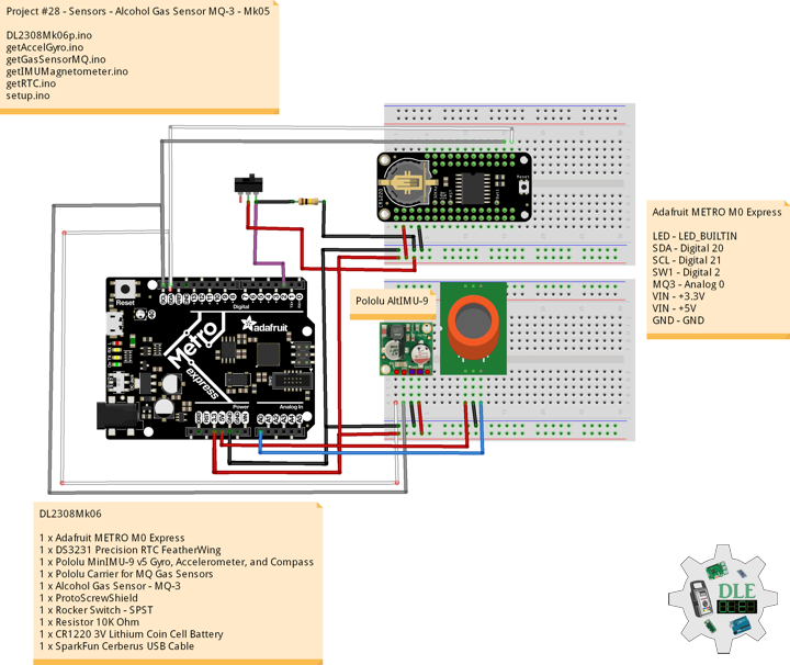
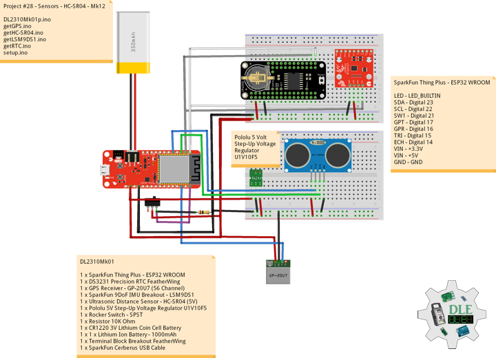
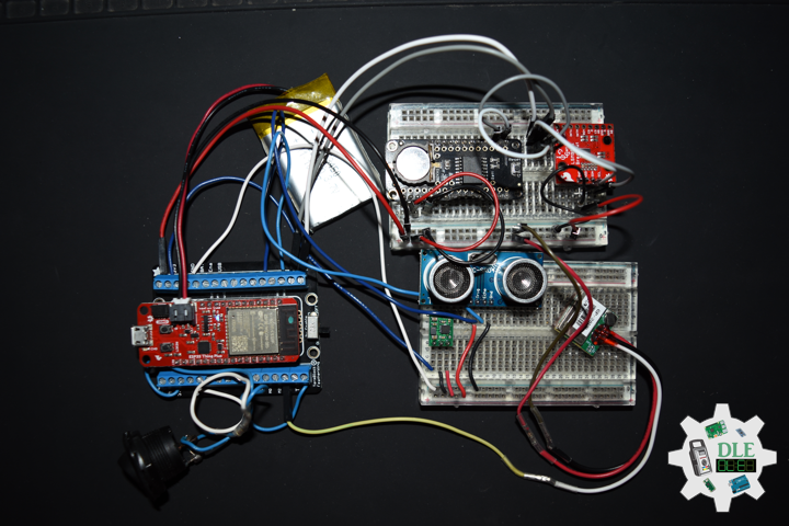
Pololu 5 Volt Step-Up Voltage Regulator U1V10F5
This tiny U1V10F5 switching step-up voltage regulator efficiently generates 5 Volt from input voltages as low as 0.5 Volt. Unlike most boost regulators, the U1V10F5 automatically switches to a linear down-regulation mode when the input voltage exceeds the output.
Ultrasonic Distance Sensor – HC-SR04 (5 Volt)
This is the HC-SR04 ultrasonic distance sensor. This economical sensor provides 2 Centimetres to 400 Centimetres of non-contact measurement functionality with a ranging accuracy that can reach up to 3 Millimetres. Each HC-SR04 module includes an ultrasonic transmitter, a receiver and a control circuit. There are only four pins that you need to worry about on the HC-SR04: VCC (Power), Trig (Trigger), Echo (Receive), and GND (Ground). This sensor has additional control circuitry that can prevent inconsistent “Bouncy” data depending on the application.
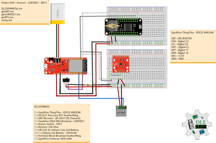
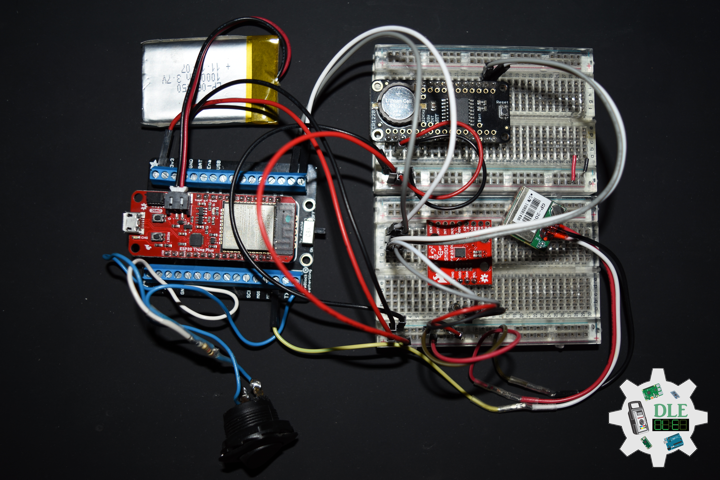
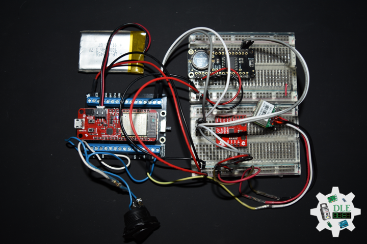
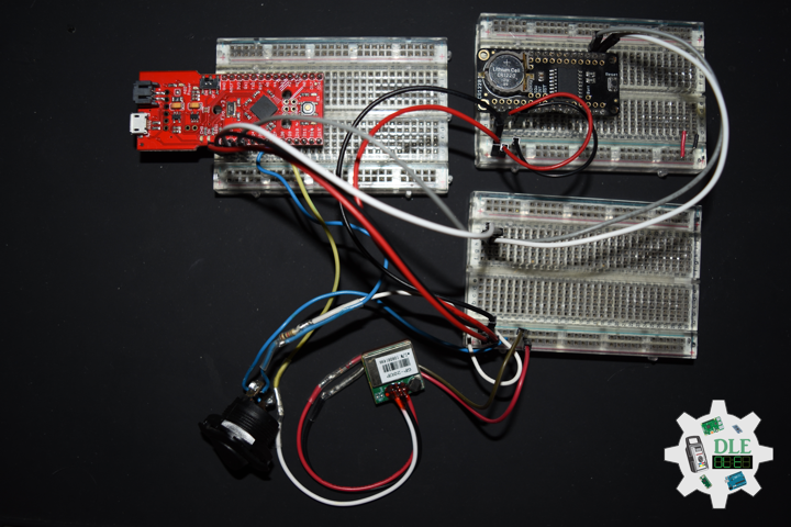
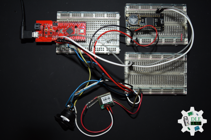
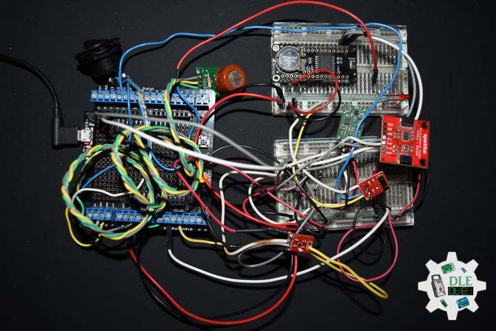
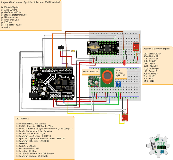
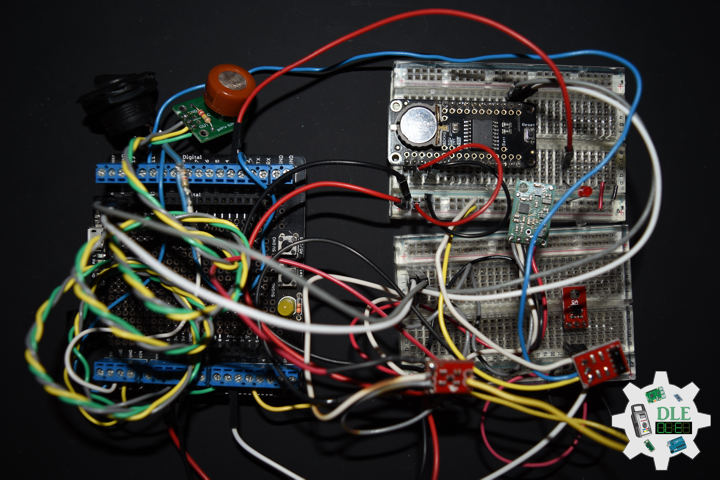
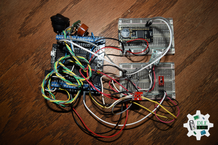
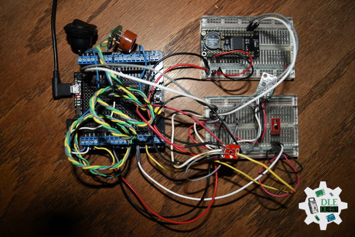
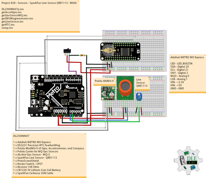
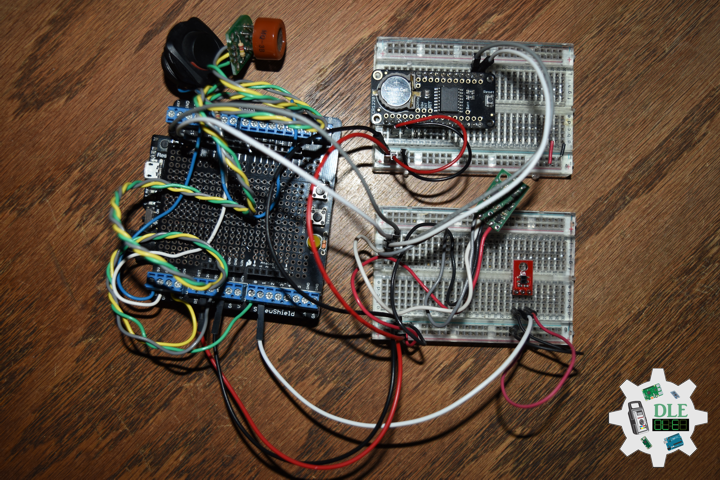
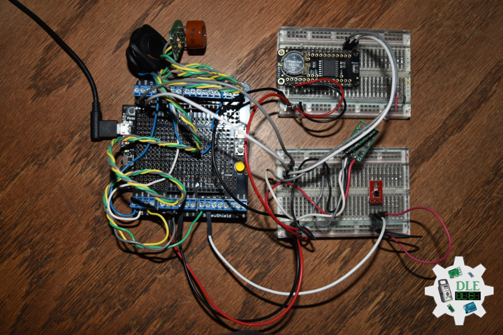
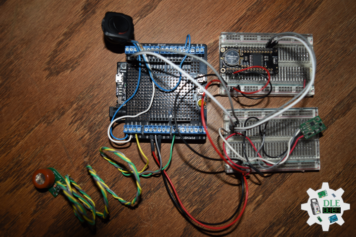
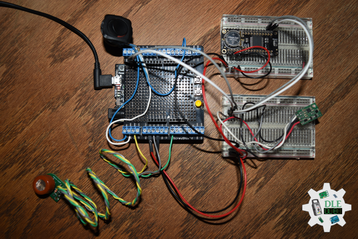
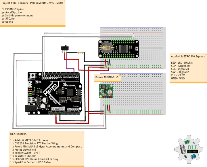
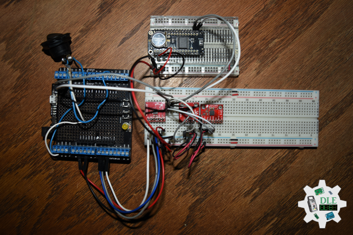
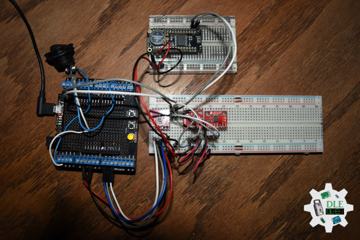
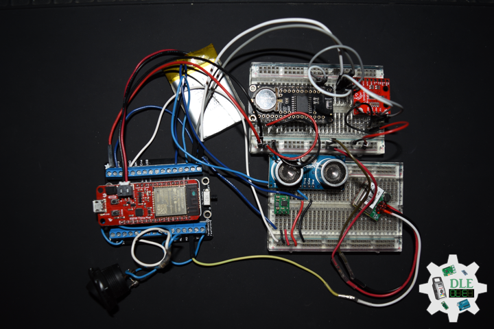
DL2310Mk01
1 x SparkFun Thing Plus – ESP32 WROOM
1 x DS3231 Precision RTC FeatherWing
1 x GPS Receiver – GP-20U7 (56 Channel)
1 x SparkFun 9DoF IMU Breakout – LSM9DS1
1 x Ultrasonic Distance Sensor – HC-SR04 (5V)
1 x Pololu 5V Step-Up Voltage Regulator U1V10F5
1 x Rocker Switch – SPST
1 x Resistor 10K Ohm
1 x CR1220 3V Lithium Coin Cell Battery
1 x 1 x Lithium Ion Battery – 1000mAh
1 x Terminal Block Breakout FeatherWing
1 x SparkFun Cerberus USB Cable
SparkFun Thing Plus – ESP32 WROOM
LED – LED_BUILTIN
SDA – Digital 23
SCL – Digital 22
SW1 – Digital 21
GPT – Digital 17
GPR – Digital 16
TRI – Digital 15
ECH – Digital 14
VIN – +3.3V
VIN – +5V
GND – GND
——
DL2310Mk01p.ino
/****** Don Luc Electronics © ******
Software Version Information
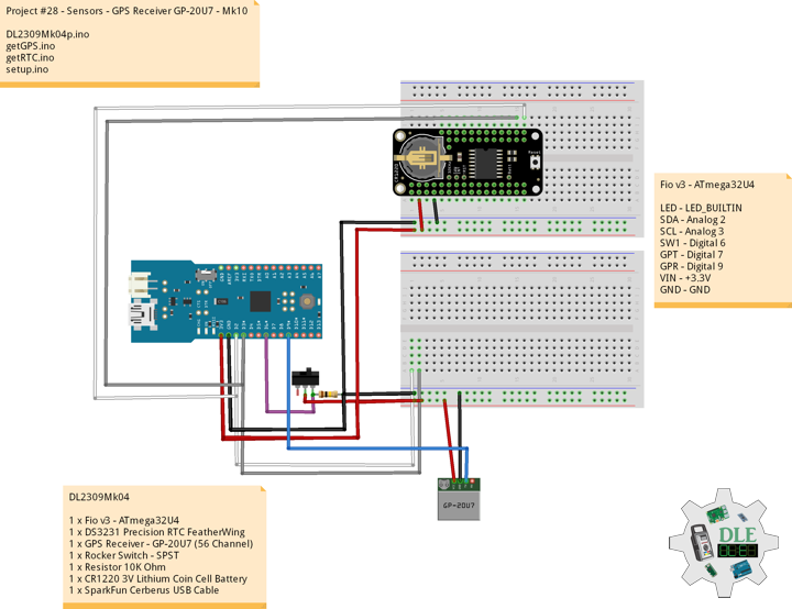
Project #28 - Sensors - HC-SR04 - Mk12
28-12
DL2310Mk01p.ino
1 x SparkFun Thing Plus - ESP32 WROOM
1 x DS3231 Precision RTC FeatherWing
1 x GPS Receiver - GP-20U7 (56 Channel)
1 x SparkFun 9DoF IMU Breakout - LSM9DS1
1 x Ultrasonic Distance Sensor - HC-SR04 (5V)
1 x Pololu 5V Step-Up Voltage Regulator U1V10F5
1 x Rocker Switch - SPST
1 x Resistor 10K Ohm
1 x Lithium Ion Battery - 1000mAh
1 x CR1220 3V Lithium Coin Cell Battery
1 x Terminal Block Breakout FeatherWing
1 x SparkFun Cerberus USB Cable
*/
// Include the Library Code
// Bluetooth LE keyboard
#include <BleKeyboard.h>
// Two Wire Interface (TWI/I2C)
#include <Wire.h>
// Serial Peripheral Interface
#include <SPI.h>
// DS3231 Precision RTC
#include <RTClib.h>
// GPS Receiver
#include <TinyGPS++.h>
// ESP32 Hardware Serial
#include <HardwareSerial.h>
// LSM9DS1 9DOF Sensor
#include <SparkFunLSM9DS1.h>
// Bluetooth LE Keyboard
BleKeyboard bleKeyboard;
String sKeyboard = "";
// Send Size
byte sendSize = 0;
// DS3231 Precision RTC
RTC_DS3231 rtc;
String dateRTC = "";
String timeRTC = "";
// GPS Receiver
#define gpsRXPIN 16
// This one is unused and doesnt have a conection
#define gpsTXPIN 17
// The TinyGPS++ object
TinyGPSPlus gps;
// Latitude
float TargetLat;
// Longitude
float TargetLon;
// GPS Date, Time
// GPS Date
String TargetDat;
// GPS Time
String TargetTim;
// GPS Status
String GPSSt = "";
// ESP32 HardwareSerial
HardwareSerial tGPS(2);
// LSM9DS1 9DOF Sensor
LSM9DS1 imu;
#define PRINT_CALCULATED
// Earth's magnetic field varies by location. Add or subtract
// a declination to get a more accurate heading. Calculate
// your's here: http://www.ngdc.noaa.gov/geomag-web/#declination
// Declination (degrees) in El Centro, CA
#define DECLINATION 10.4
// Gyro
float fGyroX;
float fGyroY;
float fGyroZ;
// Accel
float fAccelX;
float fAccelY;
float fAccelZ;
// Mag
float fMagX;
float fMagY;
float fMagZ;
// Attitude
float fRoll;
float fPitch;
float fHeading;
// HC-SR04 Ultrasonic Sensor
int iTrig = 15;
int iEcho = 14;
// Stores the distance measured by the distance sensor
float distance = 0;
// The number of the Rocker Switch pin
int iSwitch = 21;
// Variable for reading the button status
int SwitchState = 0;
// Software Version Information
String sver = "28-12";
void loop() {
// Date and Time RTC
isRTC ();
// isGPS
isGPS();
// GPS Keyboard
isGPSKeyboard();
// Gyro
isGyro();
// Accel
isAccel();
// Mag
isMag();
// Attitude
isAttitude();
// HC-SR04 Ultrasonic Sensor
isHCSR04();
// Read the state of the Switch value:
SwitchState = digitalRead(iSwitch);
// Check if the button is pressed. If it is, the SwitchState is HIGH:
if (SwitchState == HIGH) {
// Bluetooth LE Keyboard
isBluetooth();
}
// Delay 1 Second
delay(1000);
}
getBleKeyboard.ino
// Ble Keyboard
// Bluetooth
// isBluetooth
void isBluetooth() {

  // ESP32 BLE Keyboard
  if(bleKeyboard.isConnected()) {

    // Send Size Length
    sendSize = sKeyboard.length();

    // Send Size, charAt
    for(byte i = 0; i < sendSize+1; i++){

       // Write
       bleKeyboard.write(sKeyboard.charAt(i));
       delay(50);

    }
    bleKeyboard.write(KEY_RETURN);

  }

}
getGPS.ino
// GPS Receiver
// Setup GPS
void isSetupGPS() {

  // Setup GPS
  //tGPS.begin( 9600 );
  // Setup GPS
  tGPS.begin(  9600 , SERIAL_8N1 , gpsRXPIN , gpsTXPIN );

}
// isGPS
void isGPS(){

  // Receives NEMA data from GPS receiver
  // This sketch displays information every time a new sentence is correctly encoded
  while ( tGPS.available() > 0)

    if (gps.encode( tGPS.read() ))
    {

       // GPS Vector Pointer Target
       displayInfo();

       // GPS Date, Time
       displayDTS();

    }

  if (millis() > 5000 && gps.charsProcessed() < 10)
  {

     while(true);

  }

}
// GPS Vector Pointer Target
void displayInfo(){

  // Location
  if (gps.location.isValid())
  {

     // Latitude
     TargetLat = gps.location.lat();
     // Longitude
     TargetLon = gps.location.lng();
     // GPS Status 2
     GPSSt = "Yes";

  }
  else
  {

     // GPS Status 0
     GPSSt = "No";
     TargetLat = 0;
     TargetLon = 0;

  }


}
// GPS Date, Time
void displayDTS(){

  // Date
  TargetDat = "";
  if (gps.date.isValid())
  {

     // Date
     // Year
     TargetDat += String(gps.date.year(), DEC);
     TargetDat += "/";
     // Month
     TargetDat += String(gps.date.month(), DEC);
     TargetDat += "/";
     // Day
     TargetDat += String(gps.date.day(), DEC);

  }

  // Time
  TargetTim = "";
  if (gps.time.isValid())
  {

     // Time
     // Hour
     TargetTim += String(gps.time.hour(), DEC);
     TargetTim += ":";
     // Minute
     TargetTim += String(gps.time.minute(), DEC);
     TargetTim += ":";
     // Secound
     TargetTim += String(gps.time.second(), DEC);

  }

}
// GPS Keyboard
void isGPSKeyboard(){

  // GPS Keyboard
  // bleKeyboard
  // GPS Vector Pointer Target
  sKeyboard = sKeyboard + GPSSt + "|" + String(TargetLat)
  + "|" + String(TargetLon) + "|";

  // bleKeyboard
  // GPS Date, Time
  sKeyboard = sKeyboard + TargetDat + "|" +
  TargetTim + "|";

}
getHC-SR04.ino
// HC-SR04 Ultrasonic Sensor
// Setup HC-SR04
void isSetupHCSR04() {

  // The trigger iTrig will output pulses of electricity
  pinMode(iTrig, OUTPUT);
  // The echo iEcho will measure the duration of pulses coming back from the distance sensor
  pinMode(iEcho, INPUT);

}
// HC-SR04
void isHCSR04() {

  // Variable to store the distance measured by the sensor
  distance = isDistance();

  sKeyboard = sKeyboard + String(distance) + " cm|*";

}
// Distance
float isDistance() {

  // Variable to store the time it takes for a ping to bounce off an object
  float echoTime;
  // Variable to store the distance calculated from the echo time
  float calculatedDistance;

  // Send out an ultrasonic pulse that's 10ms long
  digitalWrite(iTrig, HIGH);
  delayMicroseconds(10);
  digitalWrite(iTrig, LOW);

  // Use the pulseIn command to see how long it takes for the
  // pulse to bounce back to the sensor
  echoTime = pulseIn(iEcho, HIGH);

  // Calculate the distance of the object that reflected the pulse
  // (half the bounce time multiplied by the speed of sound)
  // cm = 58.0
  calculatedDistance = echoTime / 58.0;

  // Send back the distance that was calculated
  return calculatedDistance;

}
getLSM9DS1.ino
// LSM9DS1 9DOF Sensor
// Gyro
void isGyro(){

  // Update the sensor values whenever new data is available
  if ( imu.gyroAvailable() )
  {

    // To read from the gyroscope,  first call the
    // readGyro() function. When it exits, it'll update the
    // gx, gy, and gz variables with the most current data.
    imu.readGyro();
    // If you want to print calculated values, you can use the
    // calcGyro helper function to convert a raw ADC value to
    // DPS. Give the function the value that you want to convert.
    fGyroX = imu.calcGyro(imu.gx);
    fGyroY = imu.calcGyro(imu.gy);
    fGyroZ = imu.calcGyro(imu.gz);

    // bleKeyboard
    // Gyro
    sKeyboard = sKeyboard + String(fGyroX)  + "|" + String(fGyroY)
    + "|" + String(fGyroZ) + "|";

  }

}
// Accel
void isAccel(){

    // Update the sensor values whenever new data is available
  if ( imu.accelAvailable() )
  {

    // To read from the accelerometer, first call the
    // readAccel() function. When it exits, it'll update the
    // ax, ay, and az variables with the most current data.
    imu.readAccel();
    // If you want to print calculated values, you can use the
    // calcAccel helper function to convert a raw ADC value to
    // g's. Give the function the value that you want to convert.
    fAccelX = imu.calcAccel(imu.ax);
    fAccelY = imu.calcAccel(imu.ay);
    fAccelZ = imu.calcAccel(imu.az);

    // bleKeyboard
    // Accel
    sKeyboard = sKeyboard + String(fAccelX)  + "|" + String(fAccelY)
    + "|" + String(fAccelZ) + "|";

  }

}
// Mag
void isMag(){

  // Update the sensor values whenever new data is available
  if ( imu.magAvailable() )
  {

    // To read from the magnetometer, first call the
    // readMag() function. When it exits, it'll update the
    // mx, my, and mz variables with the most current data.
    imu.readMag();
    // If you want to print calculated values, you can use the
    // calcMag helper function to convert a raw ADC value to
    // Gauss. Give the function the value that you want to convert.
    fMagX = imu.calcMag(imu.mx);
    fMagY = imu.calcMag(imu.my);
    fMagZ = imu.calcMag(imu.mz);

    // bleKeyboard
    // Mag
    sKeyboard = sKeyboard + String(fMagX)  + "|" + String(fMagY)
    + "|" + String(fMagZ) + "|";

  }

}
// Attitude
void isAttitude(){

  // Attitude
  // Roll
  fRoll = atan2(fAccelY, fAccelZ);
  // Pitch
  fPitch = atan2(-fAccelX, sqrt(fAccelY * fAccelY + fAccelZ * fAccelZ));
  // Heading
  if (fMagY == 0) {
    fHeading = (fMagX < 0) ? PI : 0;
  }
  else {
    fHeading = atan2(fMagX, fMagY);
  }

  fHeading -= DECLINATION * PI / 180;

  if (fHeading > PI) fHeading -= (2 * PI);
  else if (fHeading < -PI) fHeading += (2 * PI);

  // Convert everything from radians to degrees:
  fHeading *= 180.0 / PI;
  fPitch *= 180.0 / PI;
  fRoll  *= 180.0 / PI;

  // bleKeyboard
  // Attitude
  sKeyboard = sKeyboard + String(fHeading)  + "|" + String(fPitch)
  + "|" + String(fRoll) + "|";

}
getRTC.ino
// Date & Time
// DS3231 Precision RTC
void isSetupRTC() {

  // DS3231 Precision RTC
  if (! rtc.begin()) {
    //Serial.println("Couldn't find RTC");
    //Serial.flush();
    while (1) delay(10);
  }

  if (rtc.lostPower()) {
    //Serial.println("RTC lost power, let's set the time!");
    // When time needs to be set on a new device, or after a power loss, the
    // following line sets the RTC to the date & time this sketch was compiled
    rtc.adjust(DateTime(F(__DATE__), F(__TIME__)));
    // This line sets the RTC with an explicit date & time, for example to set
    // January 21, 2014 at 3am you would call:
    //rtc.adjust(DateTime(2023, 8, 10, 11, 0, 0));
  }

}
// Date and Time RTC
void isRTC () {

  // Date and Time
  dateRTC = "";
  timeRTC = "";
  DateTime now = rtc.now();

  // Date
  dateRTC = now.year(), DEC;
  dateRTC = dateRTC + "/";
  dateRTC = dateRTC + now.month(), DEC;
  dateRTC = dateRTC + "/";
  dateRTC = dateRTC + now.day(), DEC;

  // Time
  timeRTC = now.hour(), DEC;
  timeRTC = timeRTC + ":";
  timeRTC = timeRTC + now.minute(), DEC;
  timeRTC = timeRTC + ":";
  timeRTC = timeRTC + now.second(), DEC;

  // bleKeyboard
  sKeyboard = "SEN|" + sver + "|" + String(dateRTC)
  + "|" + String(timeRTC) + "|";

}
setup.ino
// Setup
void setup()
{

  // Give display time to power on
  delay(100);

  // Bluetooth LE keyboard
  bleKeyboard.begin();

  // Wire - Inialize I2C Hardware
  Wire.begin();

  // Give display time to power on
  delay(100);

  // Date & Time RTC
  // DS3231 Precision RTC
  isSetupRTC();

  // Give display time to power on
  delay(100);

  // GPS Receiver
  // Setup GPS
  isSetupGPS();

  // LSM9DS1 9DOF Sensor
  imu.begin();

  // Setup HC-SR04
  isSetupHCSR04();

  // Initialize the Switch pin as an input
  pinMode(iSwitch, INPUT);

  // Initialize digital pin LED_BUILTIN as an output
  pinMode(LED_BUILTIN, OUTPUT);
  // Turn the LED on HIGH
  digitalWrite(LED_BUILTIN, HIGH);

  // Delay 5 Second
  delay( 5000 );

}
——
People can contact us: https://www.donluc.com/?page_id=1927
Teacher, Instructor, E-Mentor, R&D and Consulting
- Programming Language
- Single-Board Microcontrollers (PIC, Arduino, Raspberry Pi, Arm, Silicon Labs, Espressif, Etc…)
- IoT
- Wireless (Radio Frequency, Bluetooth, WiFi, Etc…)
- Robotics
- Automation
- Camera and Video Capture Receiver Stationary, Wheel/Tank and Underwater Vehicle
- Unmanned Vehicles Terrestrial and Marine
- Machine Learning
- Artificial Intelligence (AI)
- RTOS
- eHealth Sensors, Biosensor, and Biometric
- Research & Development (R & D)
- Consulting
Follow Us
Luc Paquin – Curriculum Vitae – 2023
https://www.donluc.com/luc/
Web: https://www.donluc.com/
Facebook: https://www.facebook.com/neosteam.labs.9/
YouTube: https://www.youtube.com/@thesass2063
Twitter: https://twitter.com/labs_steam
Pinterest: https://www.pinterest.com/NeoSteamLabs/
Instagram: https://www.instagram.com/neosteamlabs/
Don Luc