PIR Motion Sensor
——
——
——
——
——
——
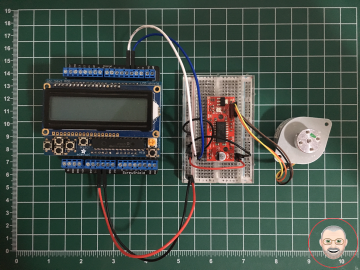
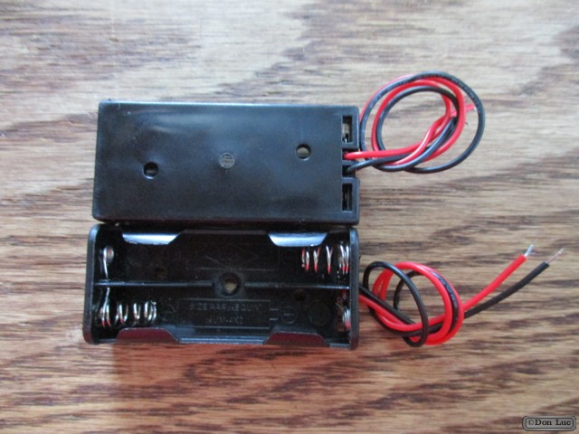
PIR Motion Sensor
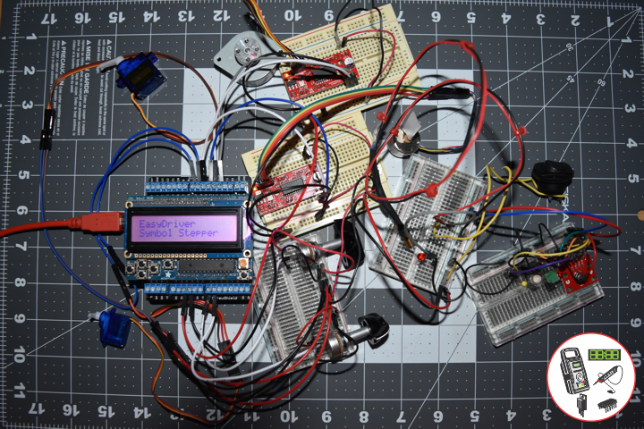
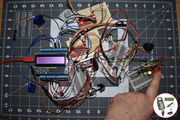
Passive infrared (PIR) sensors are motion-detecting devices used in security systems across the world, even though you may not see them, they probably see you.
This is a simple to use motion sensor. Power it up and wait 1-2 seconds for the sensor to get a snapshot of the still room. If anything moves after that period, the ‘alarm’ pin will go low.
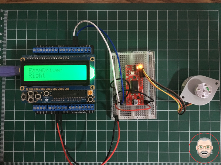
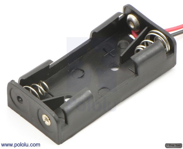
Pololu Adjustable Boost Regulator 2.5-9.5V
This powerful, adjustable boost regulator can generate an output voltage as high as 9.5 V from an input voltage as low as 1.5 V, all in a compact, 0.42″ x 0.88″ x 0.23″ package. A trimmer potentiometer lets you set the boost regulator’s output voltage to a value between 2.5 and 9.5 V.
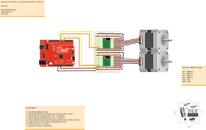
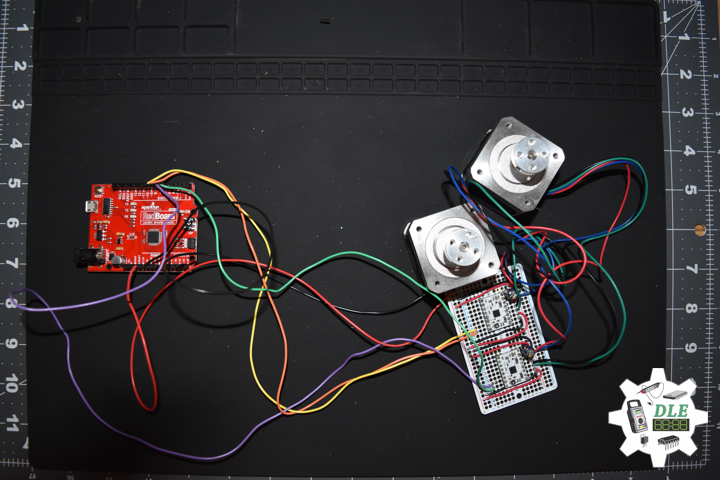
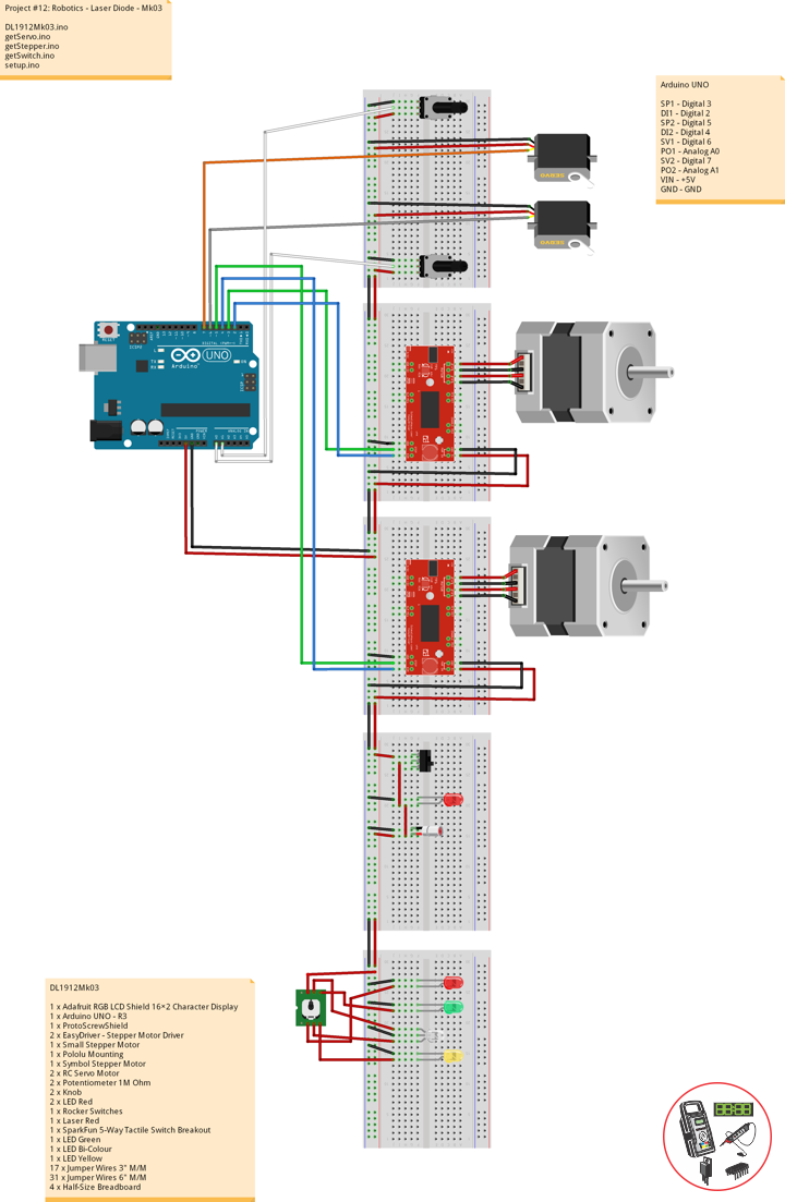
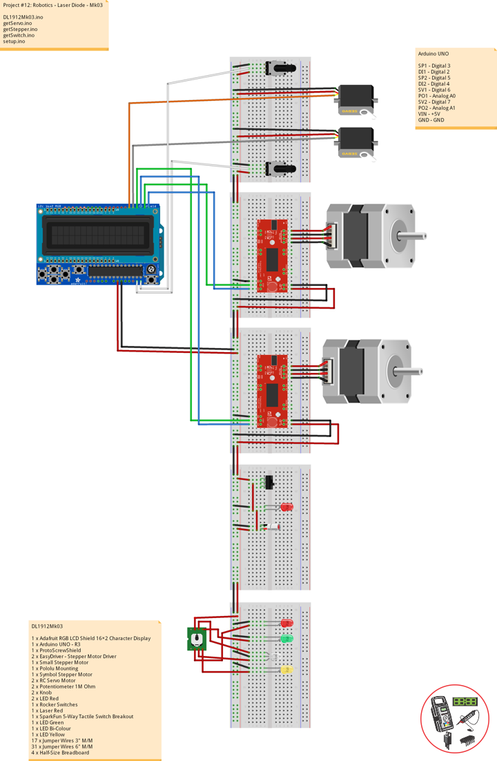
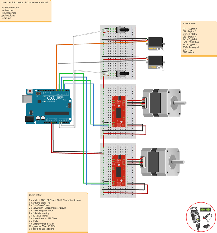
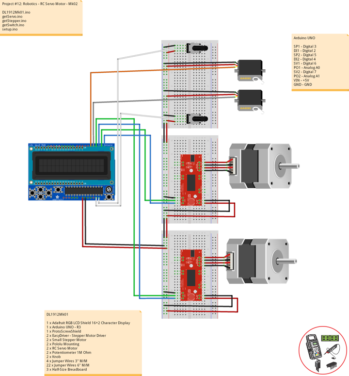
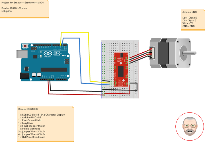
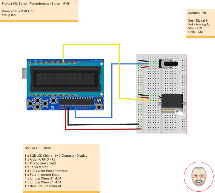
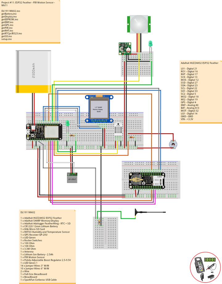
DL1911Mk02
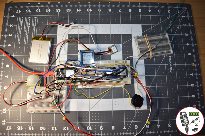
1 x Adafruit HUZZAH32 ESP32 Feather
1 x Adafruit SHARP Memory Display
1 x Adafruit Adalogger FeatherWing – RTC + SD
1 x CR1220 12mm Lithium Battery
1 x 8Gb Micro SD Card
1 x RHT03 Humidity and Temperature Sensor
1 x GPS Receiver GP-20U
1 x LED Green
1 x Rocker Switches
1 x 100 Ohm
1 x 10K Ohm
1 x 3.3M Ohm
1 x Antenna
1 x Lithium Ion Battery – 2.5Ah
1 x PIR Motion Sensor
1 x Pololu Adjustable Boost Regulator 2.5-9.5V
1 x LED Green 1
14 x Jumper Wires 3″ M/M
10 x Jumper Wires 6″ M/M
2 x Wire
1 x Full-Size Breadboard
2 x Breadboard
1 x SparkFun Cerberus USB Cable
Adafruit HUZZAH32 ESP32 Feather
LG0 – Digital 21
RO1 – Digital 16
RHT – Digital 17
SCK – Digital 13
MOS – Digital 12
SSD – Digital 27
SDA – Digital 23
SCL – Digital 22
SD1 – Digital 33
SC2 – Digital 5
MO2 – Digital 18
MI2 – Digital 19
GPS – Digital 4
EMF – Analog A0
BAT – Analog A13
MOT – Digital 32
LG1 – Digital 14
GND – GND
VIN – +3.3V
DL1911Mk02.ino
// ***** Don Luc Electronics *****
// Software Version Information
// Project #11: HUZZAH32 ESP32 Feather - PIR Motion - Mk11
// 11-02
// DL1911Mk02p.ino 11-11
// Adafruit HUZZAH32 ESP32 Feather Board
// SHARP Display
// LED Green
// Adalogger FeatherWing - RTC + SD
// EEPROM
// RHT03 Humidity and Temperature Sensor
// Rocker Switches
// GPS Receiver
// EMF Meter (Single Axis)
// Lithium Ion Battery - 2.5Ah
// PIR Motion
// Pololu Adjustable Boost Regulator 2.5-9.5V
// LED Green 1

// include Library Code
// SHARP Memory Display
#include <Adafruit_SharpMem.h>
#include <Adafruit_GFX.h>
// Date and Time
#include "RTClib.h"
// EEPROM library to read EEPROM with unique ID for unit
#include "EEPROM.h"
// RHT Humidity and Temperature Sensor
#include <SparkFun_RHT03.h>
// SD Card
#include "FS.h"
#include "SD.h"
#include "SPI.h"
// GPS Receiver
#include <TinyGPS++.h>
#include <HardwareSerial.h>

// SHARP Memory Display
// any pins can be used
#define SHARP_SCK  13
#define SHARP_MOSI 12
#define SHARP_SS   27
// Set the size of the display here, e.g. 144x168!
Adafruit_SharpMem display(SHARP_SCK, SHARP_MOSI, SHARP_SS, 144, 168);
// The currently-available SHARP Memory Display (144x168 pixels)
// requires > 4K of microcontroller RAM; it WILL NOT WORK on Arduino Uno
// or other <4K "classic" devices!
#define BLACK 0
#define WHITE 1
int minorHalfSize; // 1/2 of lesser of display width or height

// LED Green
int iLEDGreen =  21;                 // LED Green

// PCF8523 Precision RTC
RTC_PCF8523 rtc;
String dateRTC = "";
String timeRTC = "";

// RHT Humidity and Temperature Sensor
const int RHT03_DATA_PIN = 17;          // RHT03 data pin Digital 17
RHT03 rht;                              // This creates a RTH03 object, which we'll use to interact with the sensor
float latestHumidity;
float latestTempC;
float latestTempF;

// SD Card
const int chipSelect = 33;              // SD Card
String zzzzzz = "";

// Rocker Switches
int iRow1 = 16;                         // Rocker Switches Digital 16
int iRow1State = 0;                     // Variable for reading the pushbutton status

// ESP32 HardwareSerial
HardwareSerial tGPS(2);

// GPS Receiver
#define gpsRXPIN 4
#define gpsTXPIN 36                     // This one is unused and doesnt have a conection
// The TinyGPS++ object
TinyGPSPlus gps;
float TargetLat;
float TargetLon;
int Status = 0;

// EMF Meter (Single Axis)
#define NUMREADINGS 15                    // Raise this number to increase data smoothing
int senseLimit = 15;                      // Raise this number to decrease sensitivity (up to 1023 max)
int val = 0;                              // Val
int iEMF = A0;                            // EMF Meter
int readings[ NUMREADINGS ];              // Readings from the analog input
int ind = 0;                              // Index of the current reading
int total = 0;                            // Running total
int average = 0;                          // Final average of the probe reading
int iEMFDis = 0;
int iEMFRect = 0;

// LiPo Battery
const int bat = A13;                      // LiPo Battery
uint16_t vbat = 0;
int iBat = 0;

// PIR Motion
const int iMotion = 32;                   // Motion detector
const int iLEDGreen1 = 14;                // LED Green 1
int proximity = LOW;                      // Proximity
String Det = "";

// The current address in the EEPROM (i.e. which byte
// we're going to  read to next)
#define EEPROM_SIZE 64
String sver = "11-2.p";
// Unit ID information
String uid = "";

void loop() {

  // Receives NEMA data from GPS receiver
  // This sketch displays information every time a new sentence is correctly encoded.
  while ( tGPS.available() > 0)
    if (gps.encode( tGPS.read() ))
    {
     displayInfo();
    }

  if (millis() > 5000 && gps.charsProcessed() < 10)
  {
    while(true);
  }

  // Date and Time
  isRTC();

  // RHT03 Humidity and Temperature Sensor
  isRHT03();

  // SHARP Memory Display On
  isDisplayOn();

  // Rocker Switched
  // Read the state of the iRow1 value
  iRow1State = digitalRead(iRow1);

  // EMF Meter (Single Axis)
  isEMF();

  // LiPo Battery
  isBattery();

  // isPIR Motion
  isPIR();

  // Check if the pushbutton is pressed. If it is, the buttonState is HIGH:
  if (iRow1State == HIGH) {

    // iLEDGreen
    digitalWrite(iLEDGreen,  HIGH );
    // SD Card
    isSD();

  } else {

    // iLEDGreen
    digitalWrite(iLEDGreen,  LOW );

  }

  // Delay
  delay( 1000 );

}
getBattery.ino
// LiPo Battery
void isBattery() {

  // Battery
  vbat = analogRead(bat);
  vbat = vbat / 2;

  iBat = map( vbat, 1, 1064, 1, 100);

}
getDisplay.ino
// SHARP Memory Display On
void isDisplayOn() {

    // Clear Display
    display.clearDisplay();
    // Text display date, time, LED on, Etc...
    display.setRotation(4);
    display.setTextSize(2);
    display.setTextColor(BLACK);
    // Date
    display.setCursor(0,1);
    display.println( dateRTC );
    // Time
    display.setCursor(0,17);
    display.println( timeRTC );
    // Longitude
    display.setCursor(0,35);
    display.print("Lon: ");
    display.println( TargetLon );
    // Latitude
    display.setCursor(0,55);
    display.print("Lat: ");
    display.println( TargetLat );
    // Humidity
    display.setCursor(0,74);
    display.print("Hum: ");
    display.print( latestHumidity );
    display.println("%");
    // Temp C
    display.setCursor(0,94);
    display.print("Cel: ");
    display.print( latestTempC );
    display.println("*C");
    // EMF Meter
    display.setCursor(0,114);
    display.print("EMF: ");
    display.println( iEMFDis );
    // Battery
    display.setCursor(0,134);
    display.print("Bat: ");
    display.print( iBat );
    display.println( "%" );
    // PIR Motion
    display.println( Det );
    display.setCursor(0,154);
    // Refresh
    display.refresh();

}
// SHARP Memory Display - UID
void isDisplayUID() {

    // Clear Display
    display.clearDisplay();
    // text display EEPROM
    display.setRotation(4);
    display.setTextSize(2);
    display.setTextColor(BLACK);
    // EEPROM with Unique ID
    display.setCursor(0,20);
    display.print( "UID: " );
    display.println( uid );
    // Version
    display.setCursor(0,45);
    display.print( "VER: ");
    display.println( sver  );
    // Refresh
    display.refresh();
    delay( 100 );

}
getEEPROM.ino
// EEPROM
void GetUID()
{

  // Get unit ID
  uid = "";
  for (int x = 0; x < 5; x++)
  {
    uid = uid + char(EEPROM.read(x));
  }

}
getEMF.ino
// EMF Meter (Single Axis)
// setupEMF
void setupEMF() {

  // EMF Meter (Single Axis)
  pinMode( iEMF, OUTPUT ); // EMF Meter
  for (int i = 0; i < NUMREADINGS; i++){
    readings[ i ] = 0;     // Initialize all the readings to 0
  }

}
// isEMF
void isEMF(){

  // Probe
  val = analogRead( iEMF );                    // Take a reading from the probe

  if( val >= 1 ){                              // If the reading isn't zero, proceed

    val = constrain( val, 1, senseLimit );     // Turn any reading higher than the senseLimit value into the senseLimit value
    val = map( val, 1, senseLimit, 1, 1023 );  // Remap the constrained value within a 1 to 1023 range

    total -= readings[ ind ];                  // Subtract the last reading
    readings[ ind ] = val;                     // Read from the sensor
    total += readings[ ind ];                  // Add the reading to the total
    ind = ( ind + 1 );                         // Advance to the next index

    if ( ind >= NUMREADINGS ) {                // If we're at the end of the array...
      ind = 0;                                 // ...wrap around to the beginning
    }

    average = total / NUMREADINGS;             // Calculate the average


   // average = val;
  }
  else
  {

    iEMFRect = 0;
    val = 0;
    average = 0;

  }

  iEMFDis = average;
  iEMFRect = map( average, 1, 1023, 1, 144 );

}
getGPS.ino
// GPS Receiver
void setupGPS() {

  // Setup GPS
  tGPS.begin(  9600 , SERIAL_8N1, gpsRXPIN, gpsTXPIN );

}
// GPS Vector Pointer Target
void displayInfo()
{

  // Location
  if (gps.location.isValid())
  {

    TargetLat = gps.location.lat();
    TargetLon = gps.location.lng();
    Status = 2;

  }
  else
  {

    Status = 0;

  }

}
getPIR.ino
// PIR Motion
void setupPIR() {

  // Setup PIR Montion
  pinMode(iMotion, INPUT_PULLUP);
  pinMode(iLEDGreen1, OUTPUT);

}
// isPIR Motion
void isPIR() {

  // Proximity
  proximity = digitalRead(iMotion);
  if (proximity == LOW)
  {

    // PIR Motion Sensor's LOW, Motion is detected
    // LED Green 1 - HIGH
    digitalWrite(iLEDGreen1, HIGH);
    Det = "Motion!";

  }
  else
  {

    // PIR Motion Sensor's HIGH
    // LED Green 1 - LOW
    digitalWrite(iLEDGreen1, LOW);
    Det = "****";

  }

}
getRHT.ino
// RHT03 Humidity and Temperature Sensor
void isRHT03(){

  // Call rht.update() to get new humidity and temperature values from the sensor.
  int updateRet = rht.update();

  // The humidity(), tempC(), and tempF() functions can be called -- after
  // a successful update() -- to get the last humidity and temperature value
  latestHumidity = rht.humidity();
  latestTempC = rht.tempC();
  latestTempF = rht.tempF();

}
getRTCpcf8523.ino
// PCF8523 Precision RTC
void setupRTC() {

  // pcf8523 Precision RTC
  if (! rtc.begin()) {
    while (1);
  }
  if (! rtc.initialized()) {
    // Following line sets the RTC to the date & time this sketch was compiled
    rtc.adjust(DateTime(F(__DATE__), F(__TIME__)));
    // This line sets the RTC with an explicit date & time, for example to set
    // January 21, 2014 at 3am you would call:
    // rtc.adjust(DateTime(2018, 9, 29, 12, 17, 0));
  }

}
// Date and Time RTC
void isRTC () {

  // Date and Time
  DateTime now = rtc.now();
  // Date
  dateRTC = now.year(), DEC;
  dateRTC = dateRTC + "/";
  dateRTC = dateRTC + now.month(), DEC;
  dateRTC = dateRTC + "/";
  dateRTC = dateRTC + now.day(), DEC;
  // Time
  timeRTC = now.hour(), DEC;
  timeRTC = timeRTC + ":";
  timeRTC = timeRTC + now.minute(), DEC;
  timeRTC = timeRTC + ":";
  timeRTC = timeRTC + now.second(), DEC;

}
getSD.ino
// SD Card
void setupSD() {

  // SD Card
    pinMode( chipSelect , OUTPUT );
    if(!SD.begin( chipSelect )){
        ;
        return;
    }
    uint8_t cardType = SD.cardType();

    if(cardType == CARD_NONE){
        ;
        return;
    }

    //Serial.print("SD Card Type: ");
    if(cardType == CARD_MMC){
        ;
    } else if(cardType == CARD_SD){
        ;
    } else if(cardType == CARD_SDHC){
        ;
    } else {
        ;
    }

    uint64_t cardSize = SD.cardSize() / (1024 * 1024);

}
// SD Card
void isSD() {

  zzzzzz = "";

  zzzzzz = uid + "|" + sver + "|" + dateRTC + "|" + timeRTC + "|" + Status + "|" + TargetLon + "|" + TargetLat + "|" + latestHumidity + "|" + latestTempC + "|" + latestTempF + "|" + average + "|" + iBat + "|" + Det + "|\r";

  char msg[zzzzzz.length() + 1];

  zzzzzz.toCharArray(msg, zzzzzz.length() + 1);

  appendFile(SD, "/espdata.txt", msg );

}
// List Dir
void listDir(fs::FS &fs, const char * dirname, uint8_t levels){
    dirname;
    File root = fs.open(dirname);
    if(!root){
        return;
    }
    if(!root.isDirectory()){
        return;
    }

    File file = root.openNextFile();
    while(file){
        if(file.isDirectory()){
            file.name();
            if(levels){
                listDir(fs, file.name(), levels -1);
            }
        } else {
            file.name();
            file.size();
        }
        file = root.openNextFile();
    }
}
// Write File
void writeFile(fs::FS &fs, const char * path, const char * message){
    path;
    File file = fs.open(path, FILE_WRITE);
    if(!file){
        return;
    }
    if(file.print(message)){
        ;
    } else {
        ;
    }
    file.close();
}
// Append File
void appendFile(fs::FS &fs, const char * path, const char * message){
    //Serial.printf("Appending to file: %s\n", path);
    path;
    File file = fs.open(path, FILE_APPEND);
    if(!file){
        return;
    }
    if(file.print(message)){
        ;
    } else {
        ;
    }
    file.close();
}
setup.ino
// Setup
void setup() {

  // EEPROM with Unique ID
  EEPROM.begin(EEPROM_SIZE);

  // Get Unit ID
  GetUID();

  // GPS Receiver
  // Setup GPS
  setupGPS();

  // SHARP Display start & clear the display
  display.begin();
  display.clearDisplay();

  isDisplayUID();

  delay( 5000 );

  // Initialize the LED Green
  pinMode(iLEDGreen, OUTPUT);

  // PCF8523 Precision RTC
  setupRTC();

  // Date and Time RTC
  isRTC();

  // RHT03 Humidity and Temperature Sensor
  // Call rht.begin() to initialize the sensor and our data pin
  rht.begin(RHT03_DATA_PIN);

  // SD Card
  setupSD();

  // Rocker Switches
  pinMode(iRow1, INPUT);

  // EMF Meter (Single Axis)
  setupEMF();

  // PIR Motion
  setupPIR();

}
Follow Us
Web: https://www.donluc.com/
Web: http://neosteamlabs.com/
Web: http://www.jlpconsultants.com/
YouTube: https://www.youtube.com/channel/UC5eRjrGn1CqkkGfZy0jxEdA
Facebook: https://www.facebook.com/neosteam.labs.9/
Instagram: https://www.instagram.com/neosteamlabs/
Pinterest: https://www.pinterest.com/NeoSteamLabs/
Twitter: https://twitter.com/labs_steam
Etsy: https://www.etsy.com/shop/NeoSteamLabs