The Alpha Geek – Geeking Out

#09 – Stepper

Project #9: Stepper – EasyDriver – Mk04

EasyDriver – Hook-Up

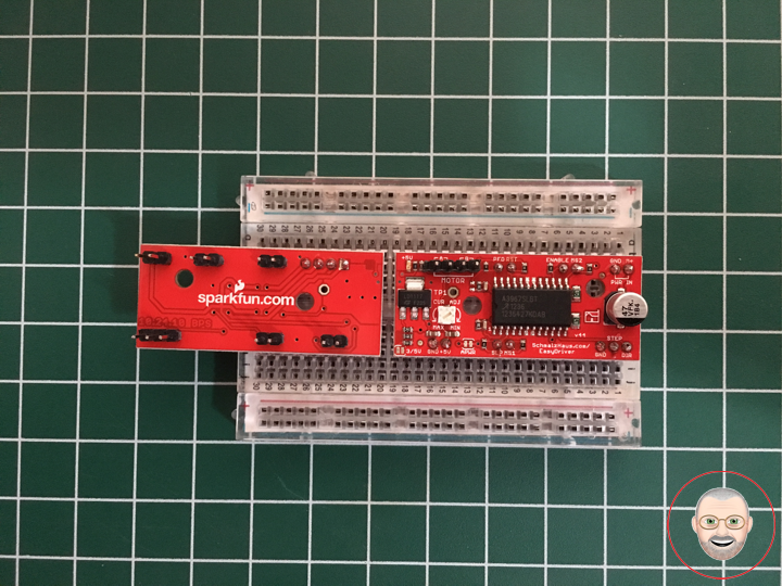
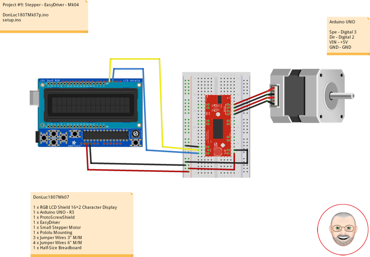
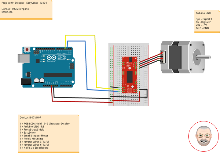
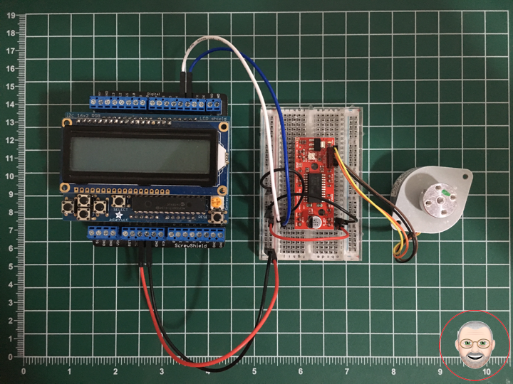
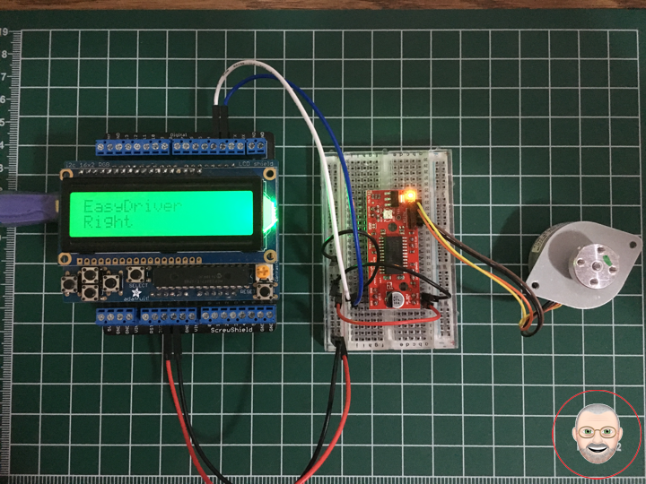
Once you have all the headers soldered on, it’s time to hook up the EasyDriver to your Arduino. Using the picture below, make all the necessary connections.

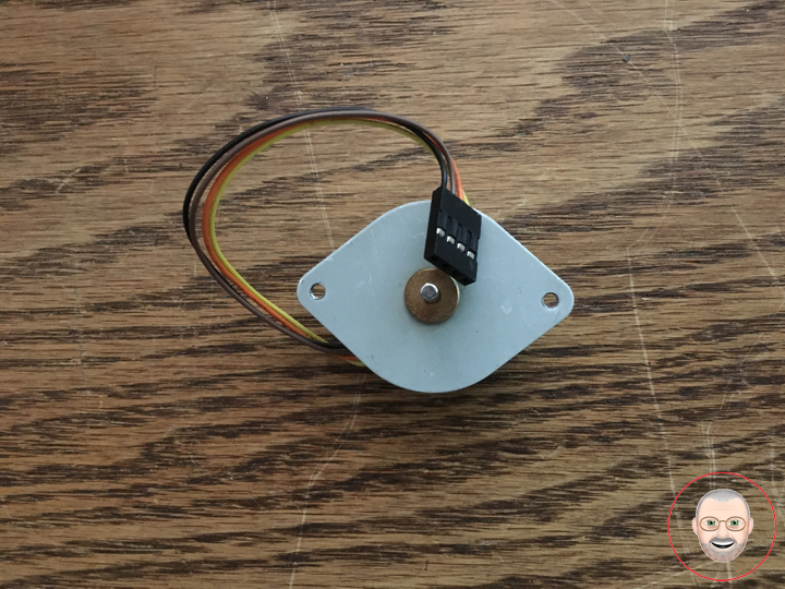
Note: The small stepper motor looks different than the one pictured. It should have a 4-pin connector on the end. This will be attached to the 4-pin male header facing upward. Because of the nature of this particular stepper, you can hook up the connector in either orientation, i.e. either the black wire on the left or the yellow wire on the left. It will work either way. If you are using a different motor, consult its documentation to find out which wires should go where.

IMPORTANT: Stepper motors require more power than can be supplied by the Arduino. In this example we will be powering the Uno with a 12V external supply. Notice that the power input (M+) on the EasyDriver is attached to the Vin pin on the Arduino. This will allow you to power both the Arduino and the motor with the same power supply.

DonLuc1807Mk07

1 x RGB LCD Shield 16×2 Character Display
1 x Arduino UNO – R3
1 x ProtoScrewShield
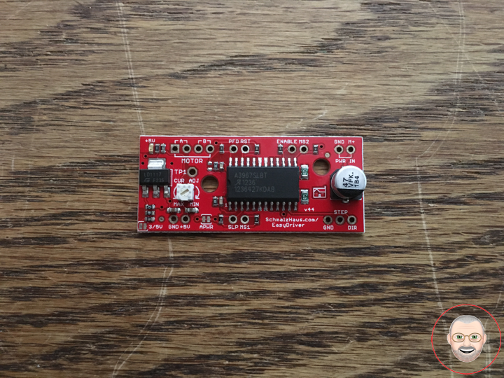
1 x EasyDriver
1 x Small Stepper Motor
1 x Pololu Mounting
3 x Jumper Wires 3″ M/M
4 x Jumper Wires 6″ M/M
1 x Half-Size Breadboard

Arduino UNO

Spe – Digital 3
Dir – Digital 2
VIN – +5V
GND – GND

DonLuc1807Mk07p.ino

// ***** Don Luc *****
// Software Version Information
// Project #9: Stepper - EasyDriver - Mk04
// 7-7
// DonLuc1807Mk07p 7-7
// Stepper
// EasyDriver

// include the library code:
#include <Adafruit_MCP23017.h>
#include <Adafruit_RGBLCDShield.h>

Adafruit_RGBLCDShield RGBLCDShield = Adafruit_RGBLCDShield();
#define GREEN 0x2

// EasyDriver
int dirPin = 2;                           // EasyDriver
int stepPin = 3;                          // stepPin

void loop() {

  // Display
  // Set the cursor to column 0, line 0  
  RGBLCDShield.setCursor(0,0);
  RGBLCDShield.print("EasyDriver");       // EasyDriver
  
  // EasyDriver
  int i;

  // Set the cursor to column 0, line 1
  RGBLCDShield.setCursor(0, 1);
  RGBLCDShield.print("Left");             // Left
  
  digitalWrite(dirPin, LOW);              // Set the direction.
  delay(100);

  for (i = 0; i<4000; i++)                // Iterate for 4000 microsteps.
  {
    digitalWrite(stepPin, LOW);           // This LOW to HIGH change is what creates the
    digitalWrite(stepPin, HIGH);          // "Rising Edge" so the easydriver knows to when to step.
    delayMicroseconds(500);               // This delay time is close to top speed for this
  }                                       // particular motor. Any faster the motor stalls.

  // Set the cursor to column 0, line 1
  RGBLCDShield.setCursor(0, 1);
  RGBLCDShield.print("Right");            // Right
  
  digitalWrite(dirPin, HIGH);             // Change direction.
  delay(2000);

  for (i = 0; i<4000; i++)                // Iterate for 4000 microsteps
  {
    digitalWrite(stepPin, LOW);           // This LOW to HIGH change is what creates the
    digitalWrite(stepPin, HIGH);          // "Rising Edge" so the easydriver knows to when to step.
    delayMicroseconds(500);               // This delay time is close to top speed for this
  }                                       // particular motor. Any faster the motor stalls.

  delay(2000);
  
  // Clear
  RGBLCDShield.clear();
  
}

setup.ino

// Setup
void setup() {

  // set up the LCD's number of columns and rows: 
  RGBLCDShield.begin(16, 2);
  RGBLCDShield.setBacklight(GREEN);
  
  // Display
  // Set the cursor to column 0, line 0  
  RGBLCDShield.setCursor(0,0);  
  RGBLCDShield.print("Don Luc");         // Don luc
  // Set the cursor to column 0, line 1
  RGBLCDShield.setCursor(0, 1);
  RGBLCDShield.print("EasyDriver");      // EasyDriver

  delay(5000);

  // Clear
  RGBLCDShield.clear();

  // EasyDriver
  pinMode(dirPin, OUTPUT);
  pinMode(stepPin, OUTPUT);

}

Don Luc

Project #9: Stepper – EasyDriver – Mk03

Assembly

The simplest way to use the EasyDriver is to attach headers to it for easy insertion onto a breadboard. Alternatively, you could solder the wires straight to the board. These instructions will assume you are using the breadboard method.

The first step is to solder straight male headers to the EasyDriver. Very few of the actual pins on the EasyDriver will be used in this example. However, soldering headers on all the broken out pins is recommended to give the board more stability when attached to a breadboard. A simple method for this is to break off the desired amount of headers, place them in the breadboard in the appropriate locations, place the EasyDriver on top, and then solder all the connections.

DonLuc1807Mk06

2 x EasyDriver
10 x 2 Header
2 x 3 Header
2 x 4 Header
2 x Half-Size Breadboard
1 x Flux-Core Solder 60/40
1 x Fume Extractor TENMA
1 x Soldering Station TENMA

Don Luc

Project #9: Stepper – EasyDriver – Mk02

EasyDriver – Stepper Motor Driver

Description

The EasyDriver is a simple to use stepper motor driver, compatible with anything that can output a digital 0 to 5V pulse (or 0 to 3.3V pulse if you solder SJ2 closed on the EasyDriver). The EasyDriver requires a 6V to 30V supply to power the motor and can power any voltage of stepper motor. The EasyDriver has an on board voltage regulator for the digital interface that can be set to 5V or 3.3V. Connect a 4-wire stepper motor and a microcontroller and you’ve got precision motor control! EasyDriver drives bi-polar motors, and motors wired as bi-polar. I.e. 4,6, or 8 wire stepper motors.

This EasyDriver V4.5 has been co-designed with Brian Schmalz. It provides much more flexibility and control over your stepper motor, when compared to older versions. The microstep select (MS1 and MS2) pins of the A3967 are broken out allowing adjustments to the microstepping resolution. The sleep and enable pins are also broken out for further control.

Note: Do not connect or disconnect a motor while the driver is energized. This will cause permanent damage to the A3967 IC.

Note: This product is a collaboration with Brian Schmalz. A portion of each sales goes back to them for product support and continued development.

Features

* A3967 Microstepping Driver
* MS1 and MS2 pins broken out to change microstepping resolution to full, half, quarter and eighth steps (defaults to eighth)
* Compatible with 4, 6, and 8 wire stepper motors of any voltage
* Adjustable current control from 150mA/phase to 700mA/phase
* Power supply range from 6V to 30V. The higher the voltage, the higher the torque at high speeds

Don Luc

Project #9: Stepper – Mk01

Stepper Motor

A stepper motor or step motor or stepping motor is a brushless DC electric motor that divides a full rotation into a number of equal steps. The motor’s position can then be commanded to move and hold at one of these steps without any position sensor for feedback (an open-loop controller), as long as the motor is carefully sized to the application in respect to torque and speed.

Switched reluctance motors are very large stepping motors with a reduced pole count, and generally are closed-loop commutated.

Fundamentals of Operation

Brushed DC motors rotate continuously when DC voltage is applied to their terminals. The stepper motor is known by its property to convert a train of input pulses (typically square wave pulses) into a precisely defined increment in the shaft position. Each pulse moves the shaft through a fixed angle.

Stepper motors effectively have multiple “toothed” electromagnets arranged around a central gear-shaped piece of iron. The electromagnets are energized by an external driver circuit or a micro controller. To make the motor shaft turn, first, one electromagnet is given power, which magnetically attracts the gear’s teeth. When the gear’s teeth are aligned to the first electromagnet, they are slightly offset from the next electromagnet. This means that when the next electromagnet is turned on and the first is turned off, the gear rotates slightly to align with the next one. From there the process is repeated. Each of those rotations is called a “step”, with an integer number of steps making a full rotation. In that way, the motor can be turned by a precise angle.

Unipolar Motors

A unipolar stepper motor has one winding with center tap per phase. Each section of windings is switched on for each direction of magnetic field. Since in this arrangement a magnetic pole can be reversed without switching the direction of current, the commutation circuit can be made very simple (e.g., a single transistor) for each winding. Typically, given a phase, the center tap of each winding is made common: giving three leads per phase and six leads for a typical two phase motor. Often, these two phase commons are internally joined, so the motor has only five leads.

Bipolar Motors

Bipolar motors have a single winding per phase. The current in a winding needs to be reversed in order to reverse a magnetic pole, so the driving circuit must be more complicated, typically with an H-bridge arrangement (however there are several off-the-shelf driver chips available to make this a simple affair). There are two leads per phase, none are common.

Small Stepper Motor

Description

These small steppers are a great way to get things moving, especially when positioning and repeatability is a concern.

When using a current limiting driver such as the Easydriver or Big Easydriver, a 12 volt power supply can be used as long as you adjust the current level to 400mA or less. If using a non current limited driver (like a L293D or an H-bridge) you will need to lower your input voltage to keep the motor current below 400mA.

This is a bipolar motor.

Features

* Stride Angle (degrees): 7.5
* 2-Phase
* Rated Voltage: 12V
* Rated Current: 400mA
* 3mm Diameter Drive Shaft
* 4-Wire Cable Attached
* In-traction Torque: 100 g/cm

Don Luc

Categories
Archives