Magnetometer
Programming and Coding
——
#DonLucElectronics #DonLuc #SparkFunRedBoard #Coding #Movement #9DOF #Magnetometer #Accelerometer #Gyroscope #Arduino #Project #Fritzing #Programming #Electronics #Microcontrollers #Consultant
——
——
——

——
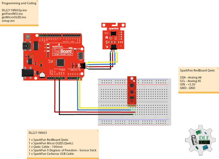
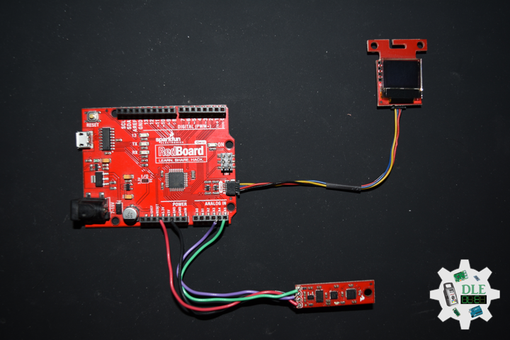
Programming and Coding
Most of the development in the world is all because of technology. Technology has grown much faster than everything else. All the technology is developed because of coding and programming. Programming and coding hold a vital role in development. It also includes developments from small projects to big projects.
The programming vs coding difference lies in the very definition of both processes. Programming is the general process of creating a program that follows certain standards and performs a certain task. Coding, on the other hand, is a part of programming that deals strictly with converting the language we understand into binary commands for the machine.
As we have discussed before in our discussion on programming vs coding, coding is just a part of programming. Yet, it still requires some time and skill to learn. Programming languages are very different from natural languages, and their syntax can sometimes be very confusing. The hardest languages are low-level ones that are close to actual processor instructions.
Programming
Programmers, on the other hand, need to review documentation and perform analysis besides coding which requires extra tools. You can find various code analysis tools, code generators, databases and testing frameworks in their inventory. Programming is passing the instructions and information to the computer that describes how a program should be carried out. Programming helps computers to perform certain actions. Various types of programming languages available in the market, like C, C++, Java, Python, etc., help develop new and creative technology.
Coding
Since coding is a simple act of translation, you don’t need much to perform it. In most cases, a simple text editor would suffice. Coding is a process of establishing a successful communication between a software program and the computer hardware. The compilers translate the program into assembly language. The coding process converts the assembly language to Binary Coded Signals.
Computer systems are electronic devices that rely on binary coded signals for communication and functioning. The two types of binary coded signals are o’s and 1’s. These signals are generated using switches and transistors. In the process of coding the high-level language and the assembly level languages are translated into binary codes and the communication between the computer hardware and software application is established.
Microcontrollers – Arduino IDE
Since the launch of the Arduino open-source platform, the brand has established themselves at the center of an expansive open-source community. The Arduino ecosystem is comprised of a diverse combination of hardware and software. The versatility of Arduino and its simple interface makes it a leading choice for a wide range of users around the world from hobbyists, designers, and artists to product prototypes.
Arduino code is written in C++ with an addition of special methods and functions, which we’ll mention later on. C++ is a human-readable programming language. When you create a “Sketch”, the name given to Arduino code files. The Arduino Integrated Development Environment (IDE) is the main text editing program used for Arduino programming. It is where you’ll be typing up your code before uploading it to the board you want to program. Arduino coding it is processed and compiled to machine language.
DL2211Mk03
1 x SparkFun RedBoard Qwiic
1 x SparkFun Micro OLED (Qwiic)
1 x Qwiic Cable – 100mm
1 x SparkFun 9 Degrees of Freedom – Sensor Stick
1 x SparkFun Cerberus USB Cable
SparkFun RedBoard Qwiic
SDA – Analog A4
SCL – Analog A5
VIN – +3.3V
GND – GND
——
DL2211Mk03p.ino
/* ***** Don Luc Electronics © *****
Software Version Information
Project #25 - Movement - 9-DOF - Mk04
25-04
DL2210Mk06p.ino
1 x SparkFun RedBoard Qwiic
1 x SparkFun Micro OLED (Qwiic)
1 x Qwiic Cable - 100mm
1 x SparkFun 9 Degrees of Freedom - Sensor Stick
1 x SparkFun Cerberus USB Cable
*/

// Include the Library Code
// Two Wire Interface (TWI/I2C)
#include <Wire.h>
// SparkFun Micro OLED
#include <SFE_MicroOLED.h>
// Includes and variables for IMU integration
// Accelerometer
#include <ADXL345.h>
// Magnetometer
#include <HMC58X3.h>
// MEMS Gyroscope
#include <ITG3200.h>
// Debug
#include "DebugUtils.h"
// FreeIMU
#include <CommunicationUtils.h>
#include <FreeIMU.h>

// Set the FreeIMU object
FreeIMU my3IMU = FreeIMU();

// Yaw Pitch Roll
float ypr[3];
float Yaw = 0;
float Pitch = 0;
float Roll = 0;

// SparkFun Micro OLED
#define PIN_RESET 9
#define DC_JUMPER 1
// I2C declaration
MicroOLED oled(PIN_RESET, DC_JUMPER);

// Software Version Information
String sver = "25-04";

void loop() {

  // isFreeIMU
  isFreeIMU();

  // Micro OLED
  isMicroOLED();

  // One delay in between reads
  delay(1000);

}
getFreeIMU.ino
// FreeIMU
// isFreeIMU
void isFreeIMU(){

  // FreeIMU
  // Yaw Pitch Roll
  my3IMU.getYawPitchRoll(ypr);
  // Yaw
  Yaw = ypr[0];
  // Pitch
  Pitch = ypr[1];
  // Roll
  Roll = ypr[2];

}
getMicroOLED.ino
// SparkFun Micro OLED
// Setup Micro OLED
void isSetupMicroOLED() {

  // Initialize the OLED
  oled.begin();
  // Clear the display's internal memory
  oled.clear(ALL);
  // Display what's in the buffer (splashscreen)
  oled.display();

  // Delay 1000 ms
  delay(1000);

  // Clear the buffer.
  oled.clear(PAGE);

}
// Micro OLED
void isMicroOLED() {

  // Text Display FreeIMU
  // Clear the display
  oled.clear(PAGE);
  // Set cursor to top-left
  oled.setCursor(0, 0);
  // Set font to type 0
  oled.setFontType(0);
  // FreeIMU
  oled.print("FreeIMU");
  oled.setCursor(0, 12);
  // Yaw
  oled.print("Y: ");
  oled.print(Yaw);
  oled.setCursor(0, 25);
  // Pitch
  oled.print("P: ");
  oled.print(Pitch);
  oled.setCursor(0, 39);
  // Roll
  oled.print("R: ");
  oled.print(Roll);
  oled.display();

}
setup.ino
// Setup
void setup() {

  // Give display time to power on
  delay(100);

  // Set up I2C bus
  Wire.begin();

  // Setup Micro OLED
  isSetupMicroOLED();

  // Pause
  delay(5);
  // Initialize IMU
  my3IMU.init();
  // Pause
  delay(5);

}
——
People can contact us: https://www.donluc.com/?page_id=1927
Technology Experience
- Single-Board Microcontrollers (PIC, Arduino, Raspberry Pi,Espressif, etc…)
- IoT
- Wireless (Radio Frequency, Bluetooth, WiFi, Etc…)
- Robotics
- Camera and Video Capture Receiver Stationary, Wheel/Tank and Underwater Vehicle
- Unmanned Vehicles Terrestrial and Marine
- Machine Learning
- RTOS
- Research & Development (R & D)
Instructor, E-Mentor, STEAM, and Arts-Based Training
- IoT
- PIC Microcontrollers
- Arduino
- Raspberry Pi
- Espressif
- Robotics
Follow Us
Luc Paquin – Curriculum Vitae – 2023
https://www.donluc.com/luc/
Web: https://www.donluc.com/
Facebook: https://www.facebook.com/neosteam.labs.9/
YouTube: https://www.youtube.com/channel/UC5eRjrGn1CqkkGfZy0jxEdA
Twitter: https://twitter.com/labs_steam
Pinterest: https://www.pinterest.com/NeoSteamLabs/
Instagram: https://www.instagram.com/neosteamlabs/
Don Luc
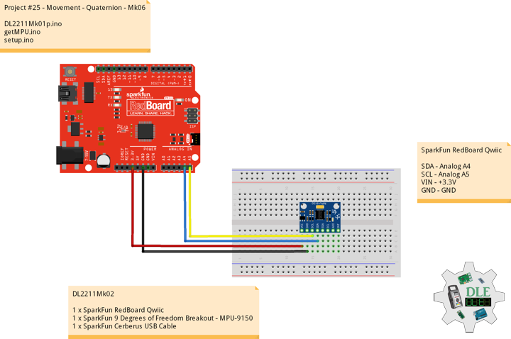
Project #25 – Movement – Quaternion – Mk06
——
#DonLucElectronics #DonLuc #SparkFunRedBoard #Movement #MPU9150 #9DOF #Quaternion #Magnetometer #Accelerometer #Gyroscope #Arduino #Project #Fritzing #Programming #Electronics #Microcontrollers #Consultant
——
——
——
——
Quaternion
In mathematics, the quaternion number system extends the complex numbers. Quaternions were first described by the Irish mathematician William Rowan Hamilton in 1843 and applied to mechanics in three-dimensional space. Hamilton defined a quaternion as the quotient of two directed lines in a three-dimensional space, as the quotient of two vectors. Multiplication of quaternions is noncommutative.
Quaternions are used in pure mathematics, but also have practical uses in applied mathematics, particularly for calculations involving three-dimensional rotations, such as in three-dimensional computer graphics, computer vision, and crystallographic texture analysis. They can be used alongside other methods of rotation, such as Euler angles and rotation matrices, or as an alternative to them, depending on the application.
SparkFun 9 Degrees of Freedom Breakout – MPU-9150
The SparkFun 9DOF MPU-9150 is the world’s first 9-axis MotionTracking MEMS device designed for the low power, low cost, and high performance requirements of consumer electronics equipment including smartphones, tablets and wearable sensors. And guess what? You get to play with it.
This breakout board makes it easy to prototype with the InvenSense MPU-9150 by breaking out all the pins you need to standard 0.1″ spaced headers. The board also provides I2C pullup resistors and a solder jumper to switch the I2C address of the device.
The MPU-9150 is a System in Package (SiP) that combines two chips: the MPU-6050, which contains a 3-axis gyroscope, 3-axis accelerometer, and an onboard Digital Motion Processor™ (DMP™) capable of processing complex MotionFusion algorithms; and the AK8975, a 3-axis digital compass. The part’s integrated 6-axis MotionFusion algorithms access all internal sensors to gather a full set of sensor data.
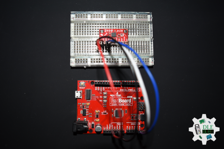
DL2211Mk02
1 x SparkFun RedBoard Qwiic
1 x SparkFun 9 Degrees of Freedom Breakout – MPU-9150
1 x SparkFun Cerberus USB Cable
SparkFun RedBoard Qwiic
SDA – Analog A4
SCL – Analog A5
VIN – +3.3V
GND – GND
——
DL2211Mk02p.ino
/* ***** Don Luc Electronics © *****
Software Version Information
Project #25 - Movement - Quaternion - Mk06
25-06
DL2211Mk02p.ino
1 x SparkFun RedBoard Qwiic
1 1 x SparkFun 9 Degrees of Freedom Breakout - MPU-9150
1 x SparkFun Cerberus USB Cable
*/

// Include the Library Code
// Two Wire Interface (TWI/I2C)
#include <Wire.h>
// I2CDev I2C utilities
#include "I2Cdev.h"
// MPU9150Lib 9-axis fusion
#include "MPU9150Lib.h"
// CalLib magnetometer and accelerometer calibration
#include "CalLib.h"
// Motion Driver InvenSense Embedded SDK v5.1
#include <dmpKey.h>
#include <dmpmap.h>
#include <inv_mpu.h>
#include <inv_mpu_dmp_motion_driver.h>
// EEPROM Magnetometer and Accelerometer data is stored
#include <EEPROM.h>

// the MPU object
MPU9150Lib MPU;
//  MPU_UPDATE_RATE defines the rate (in Hz)
// at which the MPU updates the sensor data and DMP output
#define MPU_UPDATE_RATE  (20)
//  MAG_UPDATE_RATE defines the rate (in Hz) at which the
// MPU updates the magnetometer data
//  MAG_UPDATE_RATE should be less than or equal to the MPU_UPDATE_RATE
#define MAG_UPDATE_RATE  (10)
//  MPU_MAG_MIX defines the influence that the magnetometer has on the yaw output.
//  The magnetometer itself is quite noisy so some mixing with the gyro yaw can help
//  significantly. Some example values are defined below:
// Just use gyro yaw
#define  MPU_MAG_MIX_GYRO_ONLY          0
// Just use magnetometer and no gyro yaw
#define  MPU_MAG_MIX_MAG_ONLY           1
// A good mix value
#define  MPU_MAG_MIX_GYRO_AND_MAG       10
// mainly gyros with a bit of mag correction
#define  MPU_MAG_MIX_GYRO_AND_SOME_MAG  50
//  MPU_LPF_RATE is the low pas filter rate and can be between 5 and 188Hz
#define MPU_LPF_RATE   5

// This is our earth frame gravity vector - quaternions and vectors
MPUQuaternion gravity;

//  SERIAL_PORT_SPEED defines the speed to use for the debug serial port
#define  SERIAL_PORT_SPEED  115200

// Software Version Information
String sver = "25-06";

void loop() {

  // MPU
  isMPU();

}
getMPU.ino
// MPU
// Setup MPU
void isSetupMPU() {

  // MPU
  MPU.init(MPU_UPDATE_RATE, MPU_MAG_MIX_GYRO_AND_MAG, MAG_UPDATE_RATE, MPU_LPF_RATE);     // start the MPU

  // Set up the initial gravity vector for quaternion rotation
  // Max value down the z axis
  gravity[QUAT_W] = 0;
  gravity[QUAT_X] = 0;
  gravity[QUAT_Y] = 0;
  gravity[QUAT_Z] = SENSOR_RANGE;

}
// MPU
void isMPU() {

  // Quaternion
  // This is our body frame gravity vector
  MPUQuaternion rotatedGravity;
  // This is the conjugate of the fused quaternion
  MPUQuaternion fusedConjugate;
  // Used in the rotation
  MPUQuaternion qTemp;
  // The accelerations
  MPUVector3 result;

  // Get the latest data
  if (MPU.read()) {

    // Need this for the rotation
    MPUQuaternionConjugate(MPU.m_fusedQuaternion, fusedConjugate);

    // Rotate the gravity vector into the body frame
    MPUQuaternionMultiply(gravity, MPU.m_fusedQuaternion, qTemp);
    MPUQuaternionMultiply(fusedConjugate, qTemp, rotatedGravity);

    // Now subtract rotated gravity from the body accels to get real accelerations.
    // Note that signs are reversed to get +ve acceleration results
    // in the conventional axes.
    result[VEC3_X] = -(MPU.m_calAccel[VEC3_X] - rotatedGravity[QUAT_X]);
    result[VEC3_Y] = -(MPU.m_calAccel[VEC3_Y] - rotatedGravity[QUAT_Y]);
    result[VEC3_Z] = -(MPU.m_calAccel[VEC3_Z] - rotatedGravity[QUAT_Z]);

    // print the residual accelerations
    MPU.printVector(result);
    Serial.println();

  }

}
setup.ino
// Setup
void setup() {

  // Serial
  Serial.begin(SERIAL_PORT_SPEED);
  Serial.println("Accel9150 starting");

  // Give display time to power on
  delay(100);

  // Set up I2C bus
  Wire.begin();

  // Setup MPU
  isSetupMPU();

}
——
People can contact us: https://www.donluc.com/?page_id=1927
Technology Experience
- Single-Board Microcontrollers (PIC, Arduino, Raspberry Pi,Espressif, etc…)
- IoT
- Wireless (Radio Frequency, Bluetooth, WiFi, Etc…)
- Robotics
- Camera and Video Capture Receiver Stationary, Wheel/Tank and Underwater Vehicle
- Unmanned Vehicles Terrestrial and Marine
- Machine Learning
- RTOS
- Research & Development (R & D)
Instructor and E-Mentor
- IoT
- PIC Microcontrollers
- Arduino
- Raspberry Pi
- Espressif
- Robotics
Follow Us
Luc Paquin – Curriculum Vitae – 2023
https://www.donluc.com/luc/
Web: https://www.donluc.com/
Facebook: https://www.facebook.com/neosteam.labs.9/
YouTube: https://www.youtube.com/channel/UC5eRjrGn1CqkkGfZy0jxEdA
Twitter: https://twitter.com/labs_steam
Pinterest: https://www.pinterest.com/NeoSteamLabs/
Instagram: https://www.instagram.com/neosteamlabs/
Don Luc
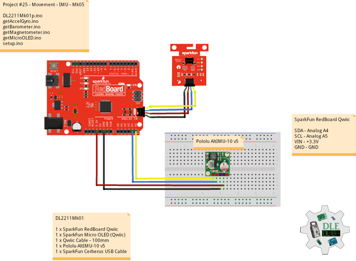
Project #25 – Movement – IMU – Mk05
——
#DonLucElectronics #DonLuc #SparkFunRedBoard #Movement #Magnetometer #Accelerometer #Gyroscope #9DOF #Barometer #Arduino #Project #Fritzing #Programming #Electronics #Microcontrollers #Consultant
——
——
——
——
Inertial Measurement Unit
An inertial measurement unit (IMU) is an electronic device that measures and reports a body’s specific force, angular rate, and sometimes the orientation of the body, using a combination of accelerometers, gyroscopes, and sometimes magnetometers. When the magnetometer is included, IMUs are referred to as IMMUs. IMUs are typically used to maneuver modern vehicles including motorcycles, missiles, aircraft, including unmanned aerial vehicles, among many others, and spacecraft, including satellites and landers. Recent developments allow for the production of IMU-enabled GPS devices. An IMU allows a GPS receiver to work when GPS-signals are unavailable, such as in tunnels, inside buildings, or when electronic interference is present.
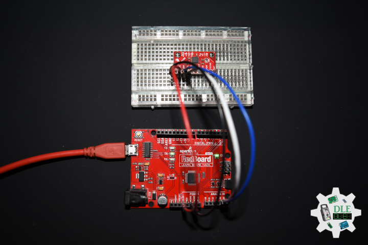
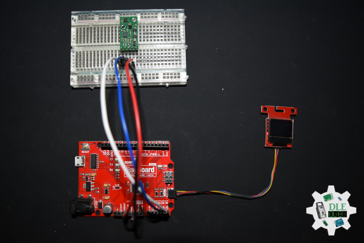
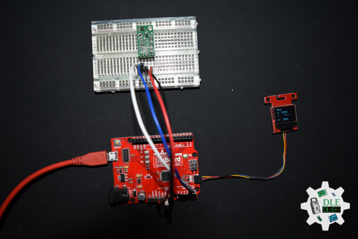
AltIMU-10 v5 Gyro, Accelerometer, Compass, and Altimeter (LSM6DS33, LIS3MDL, and LPS25H Carrier)
The Pololu AltIMU-10 v5 is an inertial measurement unit (IMU) and altimeter that features the same LSM6DS33 gyro and accelerometer and LIS3MDL magnetometer as the MinIMU-9 v5, and adds an LPS25H digital barometer. An I²C interface accesses ten independent pressure, rotation, acceleration, and magnetic measurements that can be used to calculate the sensor’s altitude and absolute orientation. The board operates from 2.5 to 5.5 V and has a 0.1″ pin spacing.
DL2211Mk01
1 x SparkFun RedBoard Qwiic
1 x SparkFun Micro OLED (Qwiic)
1 x Qwiic Cable – 100mm
1 x Pololu AltIMU-10 v5
1 x SparkFun Cerberus USB Cable
SparkFun RedBoard Qwiic
SDA – Analog A4
SCL – Analog A5
VIN – +3.3V
GND – GND
——
DL2211Mk01p.ino
/* ***** Don Luc Electronics © *****
Software Version Information
Project #25 - Movement - IMU - Mk05
25-05
DL2211Mk01p.ino
1 x SparkFun RedBoard Qwiic
1 x SparkFun Micro OLED (Qwiic)
1 x Qwiic Cable - 100mm
1 x Pololu AltIMU-10 v5
1 x SparkFun Cerberus USB Cable
*/

// Include the Library Code
// Two Wire Interface (TWI/I2C)
#include <Wire.h>
// SparkFun Micro OLED
#include <SFE_MicroOLED.h>
// Includes and variables for IMU integration
// STMicroelectronics LSM6DS33 gyroscope and accelerometer
#include <LSM6.h>
// STMicroelectronics LIS3MDL magnetometer
#include <LIS3MDL.h>
// STMicroelectronics LPS25H digital barometer
#include <LPS.h>

// 9DoF IMU
// STMicroelectronics LSM6DS33 gyroscope and accelerometer
LSM6 imu;
// Accelerometer and Gyroscopes
// Accelerometer
int imuAX;
int imuAY;
int imuAZ;
// Gyroscopes
int imuGX;
int imuGY;
int imuGZ;
// STMicroelectronics LIS3MDL magnetometer
LIS3MDL mag;
// Magnetometer
int magX;
int magY;
int magZ;
// STMicroelectronics LPS25H digital barometer
LPS ps;
// Digital Barometer
float pressure;
float altitude;
float temperature;

// SparkFun Micro OLED
#define PIN_RESET 9
#define DC_JUMPER 1
// I2C declaration
MicroOLED oled(PIN_RESET, DC_JUMPER);

// Software Version Information
String sver = "25-05";

void loop() {

  // Accelerometer and Gyroscopes
  isIMU();

  // Magnetometer
  isMag();

  // Barometer
  isBarometer();

  // Micro OLED
  isMicroOLED();

}
getAccelGyro.ino
// Accelerometer and Gyroscopes
// Setup IMU
void setupIMU() {

  // Setup IMU
  imu.init();
  // Default
  imu.enableDefault();

}
// Accelerometer and Gyroscopes
void isIMU() {

  // Accelerometer and Gyroscopes
  imu.read();
  // Accelerometer x, y, z
  imuAX = imu.a.x;
  imuAY = imu.a.y;
  imuAZ = imu.a.z;
  // Gyroscopes x, y, z
  imuGX = imu.g.x;
  imuGY = imu.g.y;
  imuGZ = imu.g.z;

}
getBarometer.ino
// STMicroelectronics LPS25H digital barometer
// Setup Barometer
void isSetupBarometer(){

  // Setup Barometer
  ps.init();
  // Default
  ps.enableDefault();

}
// Barometer
void isBarometer(){

  // Barometer
  pressure = ps.readPressureMillibars();
  // Altitude Meters
  altitude = ps.pressureToAltitudeMeters(pressure);
  // Temperature Celsius
  temperature = ps.readTemperatureC();

}
getMagnetometer.ino
// Magnetometer
// Setup Magnetometer
void setupMag() {

  // Setup Magnetometer
  mag.init();
  // Default
  mag.enableDefault();

}
// Magnetometer
void isMag() {

  // Magnetometer
  mag.read();
  // Magnetometer x, y, z
  magX = mag.m.x;
  magY = mag.m.y;
  magZ = mag.m.z;

}
getMicroOLED.ino
// SparkFun Micro OLED
// Setup Micro OLED
void isSetupMicroOLED() {

  // Initialize the OLED
  oled.begin();
  // Clear the display's internal memory
  oled.clear(ALL);
  // Display what's in the buffer (splashscreen)
  oled.display();

  // Delay 1000 ms
  delay(1000);

  // Clear the buffer.
  oled.clear(PAGE);

}
// Micro OLED
void isMicroOLED() {

  // Text Display Accelerometer
  // Clear the display
  oled.clear(PAGE);
  // Set cursor to top-left
  oled.setCursor(0, 0);
  // Set font to type 0
  oled.setFontType(0);
  // Accelerometer
  oled.print("Acceler");
  oled.setCursor(0, 12);
  // X
  oled.print("X: ");
  oled.print(imuAX);
  oled.setCursor(0, 25);
  // Y
  oled.print("Y: ");
  oled.print(imuAY);
  oled.setCursor(0, 39);
  // Z
  oled.print("Z: ");
  oled.print(imuAZ);
  oled.display();

  // Delay
  delay(3000);

  // Text Display Gyroscopes
  // Clear the display
  oled.clear(PAGE);
  // Set cursor to top-left
  oled.setCursor(0, 0);
  // Set font to type 0
  oled.setFontType(0);
  // Gyroscopes
  oled.print("Gyro");
  oled.setCursor(0, 12);
  // X
  oled.print("X: ");
  oled.print(imuGX);
  oled.setCursor(0, 25);
  // Y
  oled.print("Y: ");
  oled.print(imuGY);
  oled.setCursor(0, 39);
  // Z
  oled.print("Z: ");
  oled.print(imuGZ);
  oled.display();

  // Delay
  delay(3000);

  // Text Display Magnetometer
  // Clear the display
  oled.clear(PAGE);
  // Set cursor to top-left
  oled.setCursor(0, 0);
  // Set font to type 0
  oled.setFontType(0);
  // Magnetometer
  oled.print("Mag");
  oled.setCursor(0, 12);
  // X
  oled.print("X: ");
  oled.print(magX);
  oled.setCursor(0, 25);
  // Y
  oled.print("Y: ");
  oled.print(magY);
  oled.setCursor(0, 39);
  // Z
  oled.print("Z: ");
  oled.print(magZ);
  oled.display();

  // Delay
  delay(3000);

  // Text Display Barometer
  // Clear the display
  oled.clear(PAGE);
  // Set cursor to top-left
  oled.setCursor(0, 0);
  // Set font to type 0
  oled.setFontType(0);
  // Barometer
  oled.print("Baro");
  oled.setCursor(0, 12);
  // Pressure
  oled.print("P: ");
  oled.print(pressure);
  oled.setCursor(0, 25);
  // Altitude Meters
  oled.print("A: ");
  oled.print(altitude);
  oled.setCursor(0, 39);
  // Temperature Celsius
  oled.print("T: ");
  oled.print(temperature);
  oled.display();

  // Delay
  delay(3000);

}
setup.ino
// Setup
void setup() {

  // Give display time to power on
  delay(100);

  // Set up I2C bus
  Wire.begin();

  // Setup Micro OLED
  isSetupMicroOLED();

  // Setup IMU
  setupIMU();

  // Setup Magnetometer
  setupMag();

  // Setup Barometer
  isSetupBarometer();

}
——
People can contact us: https://www.donluc.com/?page_id=1927
Technology Experience
- Single-Board Microcontrollers (PIC, Arduino, Raspberry Pi,Espressif, etc…)
- IoT
- Wireless (Radio Frequency, Bluetooth, WiFi, Etc…)
- Robotics
- Camera and Video Capture Receiver Stationary, Wheel/Tank and Underwater Vehicle
- Unmanned Vehicles Terrestrial and Marine
- Machine Learning
- RTOS
- Research & Development (R & D)
Instructor and E-Mentor
- IoT
- PIC Microcontrollers
- Arduino
- Raspberry Pi
- Espressif
- Robotics
Follow Us
Luc Paquin – Curriculum Vitae – 2022
https://www.donluc.com/luc/
Web: https://www.donluc.com/
Facebook: https://www.facebook.com/neosteam.labs.9/
YouTube: https://www.youtube.com/channel/UC5eRjrGn1CqkkGfZy0jxEdA
Twitter: https://twitter.com/labs_steam
Pinterest: https://www.pinterest.com/NeoSteamLabs/
Instagram: https://www.instagram.com/neosteamlabs/
Don Luc
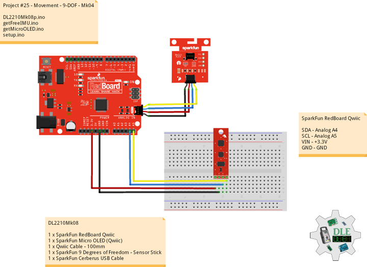
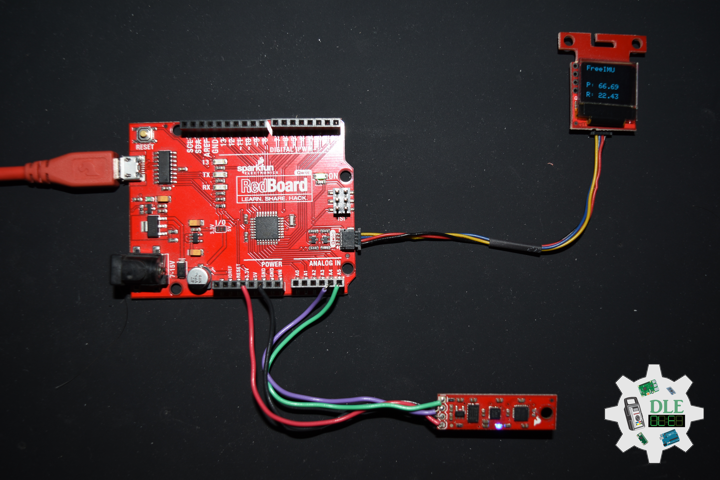
Project #25 – Movement – 9-DOF – Mk04
——
#DonLucElectronics #DonLuc #SparkFunRedBoard #Movement #9DOF #Accelerometer #Magnetometer #Gyroscope #Arduino #Project #Fritzing #Programming #Electronics #Microcontrollers #Consultant
——
——

——
——
Roll, Pitch, and Yaw
How is Controlling an Airplane or Robotic Different than Controlling a Car or Boat?
Stability and control are much more complex for an airplane, which can move freely in three dimensions, than for cars or boats, which only move in two. A change in any one of the three types of motion affects the other two.
Imagine three lines running through an airplane and intersecting at right angles at the airplane’s center of gravity.
- Rotation around the front-to-back axis is called Roll.
- Rotation around the side-to-side axis is called Pitch.
- Rotation around the vertical axis is called Yaw.
SparkFun 9 Degrees of Freedom – Sensor Stick
The SparkFun 9DOF Sensor Stick is a very small sensor board with 9 degrees of freedom. It includes the ADXL345 accelerometer, the HMC5883L magnetometer, and the ITG-3200 MEMS gyro. The “Stick” has a simple I2C interface and a mounting hole for attaching it to your project. Also, the board is a mere allowing it to be easily mounted in just about any application.
DL2210Mk08
1 x SparkFun RedBoard Qwiic
1 x SparkFun Micro OLED (Qwiic)
1 x Qwiic Cable – 100mm
1 x SparkFun 9 Degrees of Freedom – Sensor Stick
1 x SparkFun Cerberus USB Cable
SparkFun RedBoard Qwiic
SDA – Analog A4
SCL – Analog A5
VIN – +3.3V
GND – GND
——
DL2210Mk08p.ino
/* ***** Don Luc Electronics © *****
Software Version Information
Project #25 - Movement - 9-DOF - Mk04
25-04
DL2210Mk06p.ino
1 x SparkFun RedBoard Qwiic
1 x SparkFun Micro OLED (Qwiic)
1 x Qwiic Cable - 100mm
1 x SparkFun 9 Degrees of Freedom - Sensor Stick
1 x SparkFun Cerberus USB Cable
*/

// Include the Library Code
// Two Wire Interface (TWI/I2C)
#include <Wire.h>
// SparkFun Micro OLED
#include <SFE_MicroOLED.h>
// Includes and variables for IMU integration
// Accelerometer
#include <ADXL345.h>
// Magnetometer
#include <HMC58X3.h>
// MEMS Gyroscope
#include <ITG3200.h>
// Debug
#include "DebugUtils.h"
// FreeIMU
#include <CommunicationUtils.h>
#include <FreeIMU.h>

// Set the FreeIMU object
FreeIMU my3IMU = FreeIMU();

// Yaw Pitch Roll
float ypr[3];
float Yaw = 0;
float Pitch = 0;
float Roll = 0;

// SparkFun Micro OLED
#define PIN_RESET 9
#define DC_JUMPER 1
// I2C declaration
MicroOLED oled(PIN_RESET, DC_JUMPER);

// Software Version Information
String sver = "25-04";

void loop() {

  // isFreeIMU
  isFreeIMU();

  // Micro OLED
  isMicroOLED();

  // One delay in between reads
  delay(1000);

}
getFreeIMU.ino
// FreeIMU
// isFreeIMU
void isFreeIMU(){

  // FreeIMU
  // Yaw Pitch Roll
  my3IMU.getYawPitchRoll(ypr);
  // Yaw
  Yaw = ypr[0];
  // Pitch
  Pitch = ypr[1];
  // Roll
  Roll = ypr[2];

}
getMicroOLED.ino
// SparkFun Micro OLED
// Setup Micro OLED
void isSetupMicroOLED() {

  // Initialize the OLED
  oled.begin();
  // Clear the display's internal memory
  oled.clear(ALL);
  // Display what's in the buffer (splashscreen)
  oled.display();

  // Delay 1000 ms
  delay(1000);

  // Clear the buffer.
  oled.clear(PAGE);

}
// Micro OLED
void isMicroOLED() {

  // Text Display FreeIMU
  // Clear the display
  oled.clear(PAGE);
  // Set cursor to top-left
  oled.setCursor(0, 0);
  // Set font to type 0
  oled.setFontType(0);
  // FreeIMU
  oled.print("FreeIMU");
  oled.setCursor(0, 12);
  // Yaw
  oled.print("Y: ");
  oled.print(Yaw);
  oled.setCursor(0, 25);
  // Pitch
  oled.print("P: ");
  oled.print(Pitch);
  oled.setCursor(0, 39);
  // Roll
  oled.print("R: ");
  oled.print(Roll);
  oled.display();

}
setup.ino
// Setup
void setup() {

  // Give display time to power on
  delay(100);

  // Set up I2C bus
  Wire.begin();

  // Setup Micro OLED
  isSetupMicroOLED();

  // Pause
  delay(5);
  // Initialize IMU
  my3IMU.init();
  // Pause
  delay(5);

}
——
People can contact us: https://www.donluc.com/?page_id=1927
Technology Experience
- Single-Board Microcontrollers (PIC, Arduino, Raspberry Pi,Espressif, etc…)
- IoT
- Wireless (Radio Frequency, Bluetooth, WiFi, Etc…)
- Robotics
- Camera and Video Capture Receiver Stationary, Wheel/Tank and Underwater Vehicle
- Unmanned Vehicles Terrestrial and Marine
- Machine Learning
- RTOS
- Research & Development (R & D)
Instructor and E-Mentor
- IoT
- PIC Microcontrollers
- Arduino
- Raspberry Pi
- Espressif
- Robotics
Follow Us
Luc Paquin – Curriculum Vitae – 2022
https://www.donluc.com/luc/
Web: https://www.donluc.com/
Facebook: https://www.facebook.com/neosteam.labs.9/
YouTube: https://www.youtube.com/channel/UC5eRjrGn1CqkkGfZy0jxEdA
Twitter: https://twitter.com/labs_steam
Pinterest: https://www.pinterest.com/NeoSteamLabs/
Instagram: https://www.instagram.com/neosteamlabs/
Don Luc
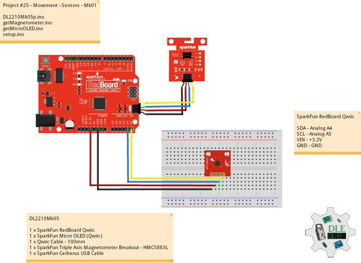
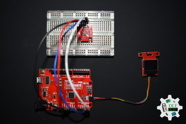
Project #25 – Movement – Sensors – Mk01
——
#DonLucElectronics #DonLuc #SparkFunRedBoard #Movement #Magnetometer #Arduino #Project #Fritzing #Programming #Electronics #Microcontrollers #Consultant
——
——
——
——
Movement
Accelerometers, gyroscopes, and magnetometers are the three main sensors we use for detecting motion and orientation. We can sense motion with an accelerometer.
Accelerometers are used to measure acceleration, that means linear motion in X, Y or Z. They can be used to detect when they are being moved around, detect motion, shock or vibration. They can also be used to detect gravitational pull in order to detect orientation or tilt.
Gyroscopes are used to measure rotational motion in X, Y or Z. They are often paired with accelerometers for inertial guidance systems, 3D motion capture and inverted pendulum type applications.
Magnetometers can sense where the strongest magnetic force is coming from, generally used to detect magnetic north, but can also be used for measuring magnetic fields. When combined with accelerometers and gyroscopes you can stabilize orientation calculations and also determine orientation with respect to the Earth.
Many 6-DoF sensors, which combine accelerometer and gyroscope or compass, accelerometer and magnetometer, and 9-DoF sensors that have 9DoF IMU accelerometers and gyroscopes and magnetometers.
DL2210Mk05
1 x SparkFun RedBoard Qwiic
1 x SparkFun Micro OLED (Qwiic)
1 x Qwiic Cable – 100mm
1 x SparkFun Triple Axis Magnetometer Breakout – HMC5883L
1 x SparkFun Cerberus USB Cable
SparkFun RedBoard Qwiic
SDA – Analog A4
SCL – Analog A5
VIN – +3.3V
GND – GND
DL2210Mk05p.ino
/* ***** Don Luc Electronics © *****
Software Version Information
Project #25 - Movement - Sensors - Mk01
25-01
DL2210Mk05p.ino
1 x SparkFun RedBoard Qwiic
1 x SparkFun Micro OLED (Qwiic)
1 x Qwiic Cable - 100mm
1 x SparkFun Triple Axis Magnetometer Breakout - HMC5883L
1 x SparkFun Cerberus USB Cable
*/

// Include the Library Code
// Two Wire Interface (TWI/I2C)
#include <Wire.h>
// Triple Axis Magnetometer
#include <HMC5883L.h>
// SparkFun Micro OLED
#include <SFE_MicroOLED.h>

// Triple Axis Magnetometer
HMC5883L compass;

// SparkFun Micro OLED
#define PIN_RESET 9
#define DC_JUMPER 1
// I2C declaration
MicroOLED oled(PIN_RESET, DC_JUMPER);

// Triple Axis Magnetometer
int X = 0;
int Y = 0;
int Z = 0;

// Software Version Information
String sver = "25-01";

void loop() {

  // Triple Axis Magnetometer
  isMagnetometer(),

  // Micro OLED
  isMicroOLED();

  // One delay in between reads
  delay(1000);

}
getMagnetometer.ino
// Magnetometer
// Setup Magnetometer
void isSetupMagnetometer(){

  // Magnetometer Serial
  // Initialize HMC5883L
  while (!compass.begin())
  {
    delay(500);
  }

  // Set measurement range
  // +/- 1.30 Ga: HMC5883L_RANGE_1_3GA (default)
  compass.setRange(HMC5883L_RANGE_1_3GA);

  // Set measurement mode
  // Continuous-Measurement: HMC5883L_CONTINOUS (default)
  compass.setMeasurementMode(HMC5883L_CONTINOUS);

  // Set data rate
  // 15.00Hz: HMC5883L_DATARATE_15HZ (default)
  compass.setDataRate(HMC5883L_DATARATE_15HZ);

  // Set number of samples averaged
  // 1 sample:  HMC5883L_SAMPLES_1 (default)
  compass.setSamples(HMC5883L_SAMPLES_1);

}
// Magnetometer
void isMagnetometer(){

  // Vector Norm
  Vector norm = compass.readNormalize();
  // Vector X, Y, Z
  // X Normalize
  X = norm.XAxis;
  // Y Normalize
  Y = norm.YAxis;
  // Z Normalize
  Z = norm.ZAxis;

}
getMicroOLED.ino
// SparkFun Micro OLED
// Setup Micro OLED
void isSetupMicroOLED() {

  // Initialize the OLED
  oled.begin();
  // Clear the display's internal memory
  oled.clear(ALL);
  // Display what's in the buffer (splashscreen)
  oled.display();

  // Delay 1000 ms
  delay(1000);

  // Clear the buffer.
  oled.clear(PAGE);

}
// Micro OLED
void isMicroOLED() {

  // Text Display Magnetometer
  // Clear the display
  oled.clear(PAGE);
  // Set cursor to top-left
  oled.setCursor(0, 0);
  // Set font to type 0
  oled.setFontType(0);
  // Magnetometer
  oled.print("Magneto");
  oled.setCursor(0, 12);
  // X Normalize
  oled.print("X: ");
  oled.print(X);
  oled.setCursor(0, 25);
  // Y Normalize
  oled.print("Y: ");
  oled.print(Y);
  oled.setCursor(0, 39);
  // Z Normalize
  oled.print("Z: ");
  oled.print(Z);
  oled.display();

}
setup.ino
// Setup
void setup() {

  // Give display time to power on
  delay(100);

  // Set up I2C bus
  Wire.begin();

  // Setup Triple Axis Magnetometer
  isSetupMagnetometer();

  // Setup Micro OLED
  isSetupMicroOLED();

}
——
People can contact us: https://www.donluc.com/?page_id=1927
Technology Experience
- Single-Board Microcontrollers (PIC, Arduino, Raspberry Pi,Espressif, etc…)
- IoT
- Wireless (Radio Frequency, Bluetooth, WiFi, Etc…)
- Robotics
- Camera and Video Capture Receiver Stationary, Wheel/Tank and Underwater Vehicle
- Unmanned Vehicles Terrestrial and Marine
- Machine Learning
- RTOS
- Research & Development (R & D)
Instructor and E-Mentor
- IoT
- PIC Microcontrollers
- Arduino
- Raspberry Pi
- Espressif
- Robotics
Follow Us
J. Luc Paquin – Curriculum Vitae – 2022 English & Español
https://www.jlpconsultants.com/luc/
Web: https://www.donluc.com/
Web: https://www.jlpconsultants.com/
Facebook: https://www.facebook.com/neosteam.labs.9/
YouTube: https://www.youtube.com/channel/UC5eRjrGn1CqkkGfZy0jxEdA
Twitter: https://twitter.com/labs_steam
Pinterest: https://www.pinterest.com/NeoSteamLabs/
Instagram: https://www.instagram.com/neosteamlabs/
Don Luc
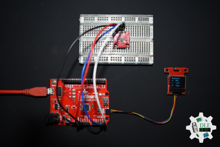
Project #24 – RTOS – Magnetometers HMC5883L – Mk02
——
#DonLucElectronics #DonLuc #SparkFunRedBoard #RTOS #FreeRTOS #Magnetometer #Arduino #Project #Fritzing #Programming #Electronics #Microcontrollers #Consultant
——
——
——
——
SparkFun Triple Axis Magnetometer Breakout – HMC5883L
This is a breakout board for Honeywell’s HMC5883L, a 3-axis digital compass. Communication with the HMC5883L is simple and all done through an I2C interface. There is no on-board regulator, so a regulated voltage of 2.16-3.6VDC should be supplied. The breakout board includes the HMC5883L sensor and all filtering capacitors as shown. The power and 2-wire interface pins are all broken out to a 0.1″ pitch header.
Magnetometers have a wide range of uses. The most common include using the chip as a digital compass to sense direction or using them to detect ferrous (magnetic) metals. Magnetic fields and current go hand-in-hand. When current flows through a wire, a magnetic field is created. This is the basic principle behind electromagnets. This is also the principle used to measure magnetic fields with a magnetometer. The direction of Earth’s magnetic fields affects the flow of electrons in the sensor, and those changes in current can be measured and calculated to derive a compass heading or other useful information.
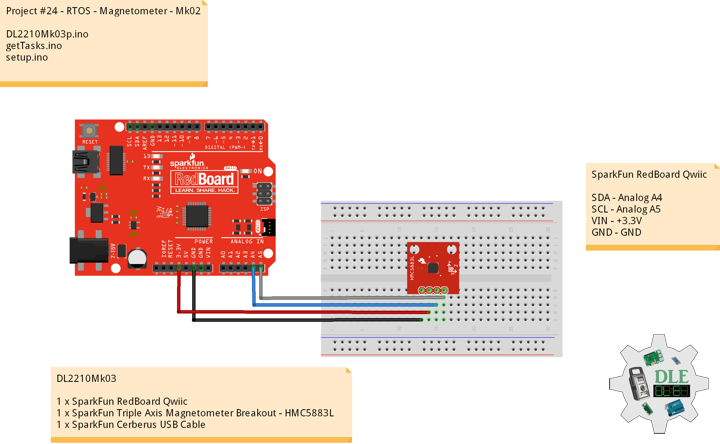
DL2210Mk03
1 x SparkFun RedBoard Qwiic
1 x SparkFun Triple Axis Magnetometer Breakout – HMC5883L
1 x SparkFun Cerberus USB Cable
SparkFun RedBoard Qwiic
SDA – Analog A4
SCL – Analog A5
VIN – +3.3V
GND – GND
DL2210Mk03p.ino
/* ***** Don Luc Electronics © *****
Software Version Information
Project #24 - RTOS - Magnetometer - Mk02
24-02
DL2210Mk03p.ino
1 x SparkFun RedBoard Qwiic
1 x SparkFun Triple Axis Magnetometer Breakout - HMC5883L
1 x SparkFun Cerberus USB Cable
*/

// Include the Library Code
// FreeRTOS
#include <Arduino_FreeRTOS.h>
// Two Wire Interface (TWI/I2C)
#include <Wire.h>
// Triple Axis Magnetometer
#include <HMC5883L.h>

// Define two tasks for Triple Axis Magnetometer
void isTaskMagnetometer( void *pvParameters );

// Software Version Information
String sver = "24-02";

void loop() {

  // Empty. Things are done in Tasks.

}
getTasks.ino
// Tasks
// Setup Task
void isSetupTask(){

  // Now set up one tasks to run independently
  // Magnetometer
  //xTaskCreatePinnedToCore(
  xTaskCreate(
    isTaskMagnetometer
    ,  "Magnetometer"
    ,  128  // Stack size
    ,  NULL
    ,  1  // Priority
    ,  NULL);

  // Now the task scheduler, which takes over control of scheduling individual tasks,
  // is automatically started.

}
// This is a Task Magnetometer Serial
void isTaskMagnetometer(void *pvParameters)
{

  (void) pvParameters;

  // Triple Axis Magnetometer
  HMC5883L compass;

  // Magnetometer Serial
  // Initialize HMC5883L
  Serial.println("Initialize HMC5883L");
  while (!compass.begin())
  {
    Serial.println("Could not find a valid HMC5883L sensor, check wiring!");
    delay(500);
  }

  // Set measurement range
  // +/- 1.30 Ga: HMC5883L_RANGE_1_3GA (default)
  compass.setRange(HMC5883L_RANGE_1_3GA);

  // Set measurement mode
  // Continuous-Measurement: HMC5883L_CONTINOUS (default)
  compass.setMeasurementMode(HMC5883L_CONTINOUS);

  // Set data rate
  // 15.00Hz: HMC5883L_DATARATE_15HZ (default)
  compass.setDataRate(HMC5883L_DATARATE_15HZ);

  // Set number of samples averaged
  // 1 sample:  HMC5883L_SAMPLES_1 (default)
  compass.setSamples(HMC5883L_SAMPLES_1);

  for (;;)
  {

    // Vector Norm
    Vector norm = compass.readNormalize();
    // Vector X, Y, Z
    Serial.print("Xnorm = ");
    Serial.print(norm.XAxis);
    Serial.print(" Ynorm = ");
    Serial.print(norm.YAxis);
    Serial.print(" ZNorm = ");
    Serial.print(norm.ZAxis);
    Serial.println();
    // One tick delay in between reads
    vTaskDelay(500);

  }

}
setup.ino
// Setup
void setup() {

  // Initialize serial communication
  // at 9600 bits per second:
  Serial.begin(9600);

  // Setup Task
  isSetupTask();

}
——
People can contact us: https://www.donluc.com/?page_id=1927
Technology Experience
- Single-Board Microcontrollers (PIC, Arduino, Raspberry Pi,Espressif, etc…)
- IoT
- Robotics
- Camera and Video Capture Receiver Stationary, Wheel/Tank and Underwater Vehicle
- Unmanned Vehicles Terrestrial and Marine
- Research & Development (R & D)
Instructor and E-Mentor
- IoT
- PIC Microcontrollers
- Arduino
- Raspberry Pi
- Espressif
- Robotics
Follow Us
J. Luc Paquin – Curriculum Vitae – 2022 English & Español
https://www.jlpconsultants.com/luc/
Web: https://www.donluc.com/
Web: https://www.jlpconsultants.com/
Facebook: https://www.facebook.com/neosteam.labs.9/
YouTube: https://www.youtube.com/channel/UC5eRjrGn1CqkkGfZy0jxEdA
Twitter: https://twitter.com/labs_steam
Pinterest: https://www.pinterest.com/NeoSteamLabs/
Instagram: https://www.instagram.com/neosteamlabs/
Don Luc