——
#DonLucElectronics #DonLuc #DFRobot #ASM #Smoke #CH4 #VOC #SHTC3 #SD #FireBeetle2ESP32E #Display #EEPROM #ESP32 #IoT #Arduino #Project #Fritzing #Programming #Electronics #Microcontrollers #Consultant
——
——
——
——
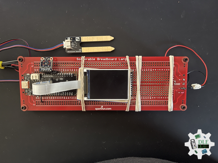
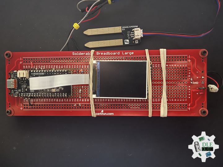
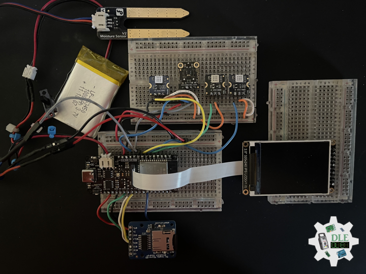
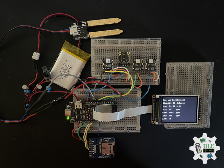
Gravity: Analog Soil Moisture Sensor
A soil moisture sensor can read the amount of moisture present in the soil surrounding it. It’s an ideal for monitoring an urban garden, or your pet plant’s water level. This is a must have component for a IOT garden / Agriculture. The new soil moisture sensor uses Immersion Gold which protects the nickel from oxidation. Electroless nickel immersion gold has several advantages over more conventional surface platings such as HASL, including excellent surface planarity, good oxidation resistance, and usability for untreated contact surfaces such as membrane switches and contact points. This soil moisture arduino sensor uses the two probes to pass current through the soil, and then it reads that resistance to get the moisture level. More water makes the soil conduct electricity more easily, while dry soil conducts electricity poorly. This sensor will be helpful to remind you to water your indoor plants or to monitor the soil moisture in your garden.
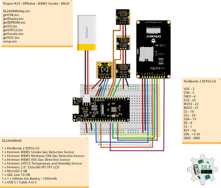
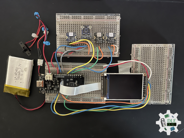
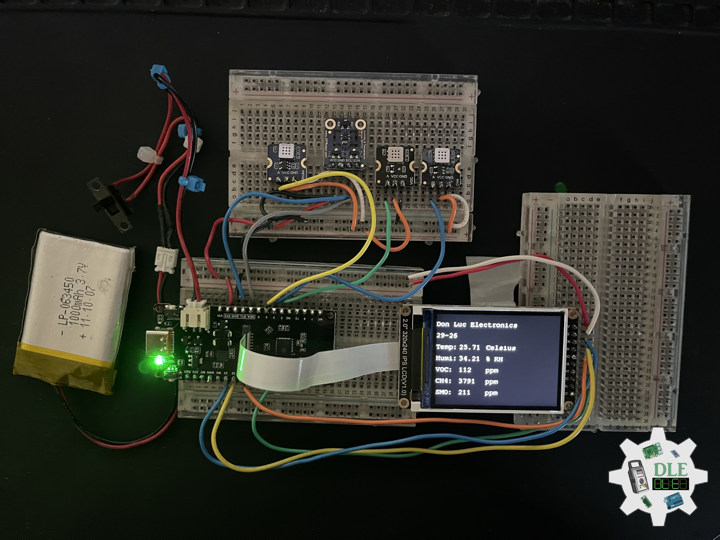
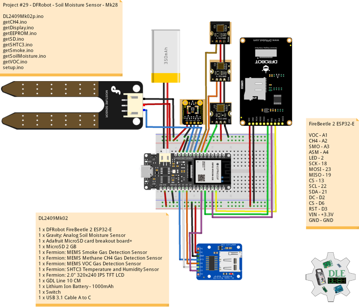
DL2409Mk02
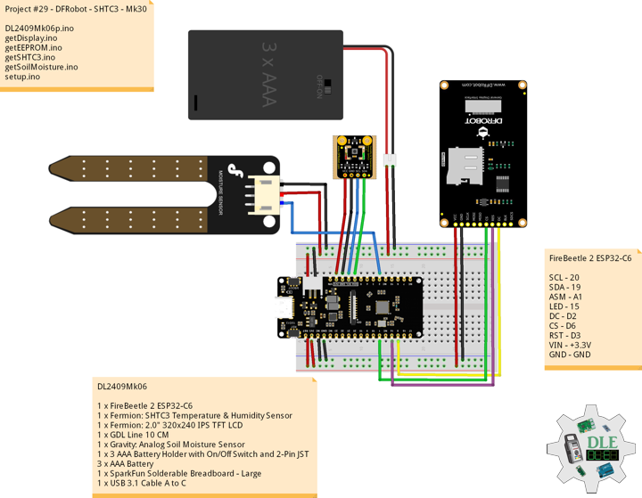
1 x DFRobot FireBeetle 2 ESP32-E
1 x Gravity: Analog Soil Moisture Sensor
1 x Adafruit MicroSD card breakout board+
1 x MicroSD 2 GB
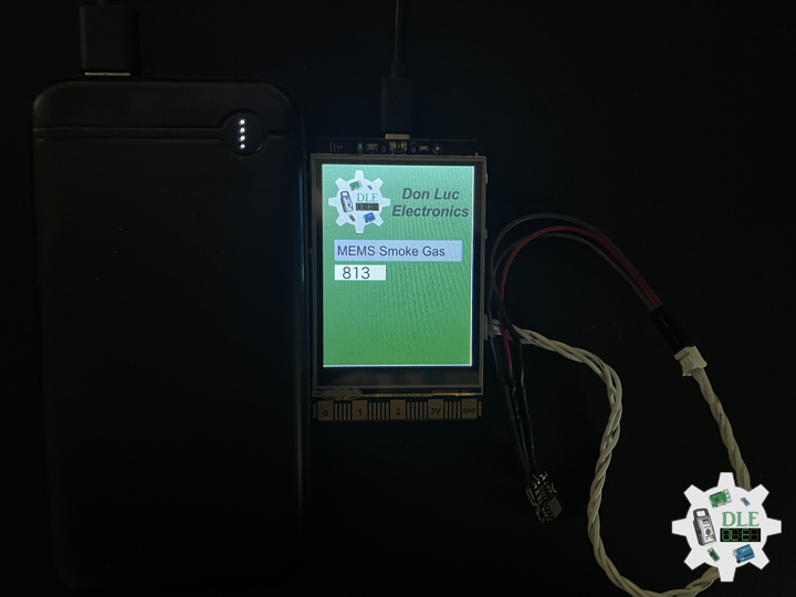
1 x Fermion: MEMS Smoke Gas Detection Sensor
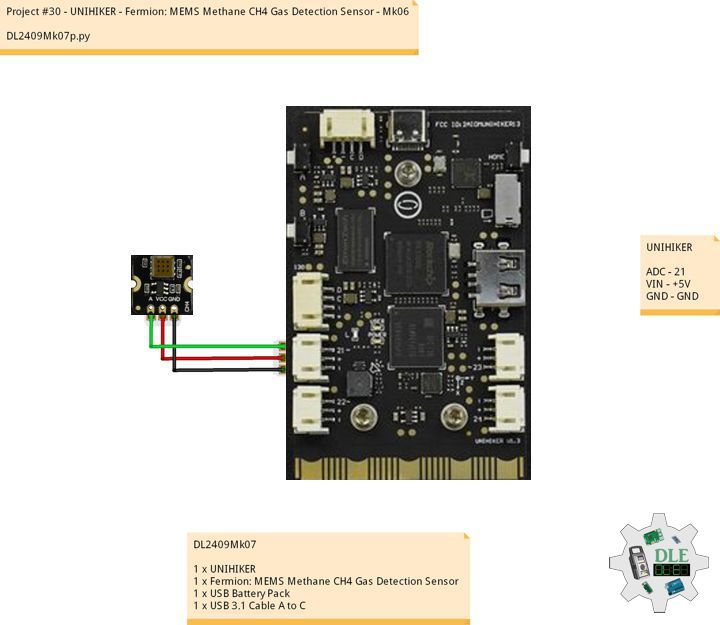
1 x Fermion: MEMS Methane CH4 Gas Detection Sensor
1 x Fermion: MEMS VOC Gas Detection Sensor
1 x Fermion: SHTC3 Temperature and Humidity Sensor
1 x Fermion: 2.0″ 320×240 IPS TFT LCD
1 x GDL Line 10 CM
1 x Lithium Ion Battery – 1000mAh
1 x Switch
1 x USB 3.1 Cable A to C
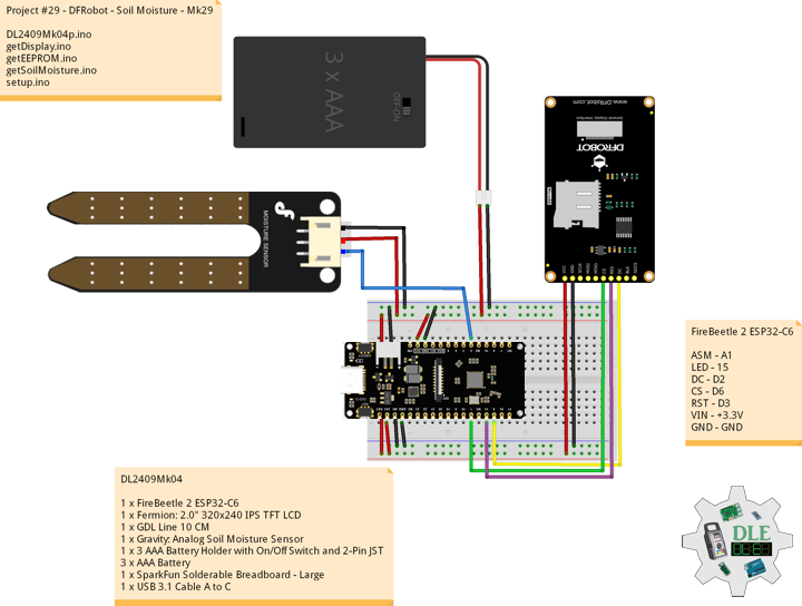
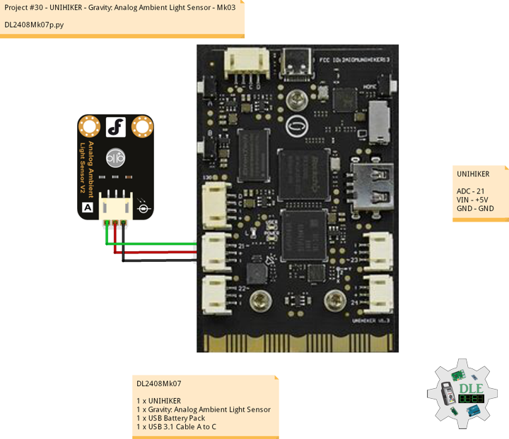
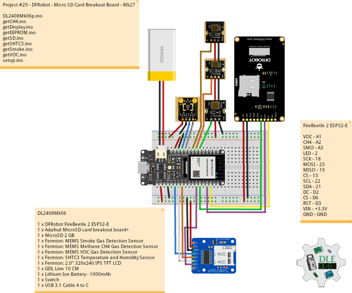
FireBeetle 2 ESP32-E
VOC – A1
CH4 – A2
SMO – A3
ASM – A4
LED – 2
SCK – 18
MOSI – 23
MISO – 19
CS – 13
SCL – 22
SDA – 21
DC – D2
CS – D6
RST – D3
VIN – +3.3V
GND – GND
DL2409Mk02p
DL2409Mk02p.ino
/****** Don Luc Electronics © ******
Software Version Information
Project #29 - DFRobot - Soil Moisture Sensor - Mk28
29-28
DL2409Mk02p.ino
DL2409Mk02
1 x DFRobot FireBeetle 2 ESP32-E
1 x Gravity: Analog Soil Moisture Sensor
1 x Adafruit MicroSD card breakout board+
1 x MicroSD 2 GB
1 x Fermion: MEMS Smoke Gas Detection Sensor
1 x Fermion: MEMS Methane CH4 Gas Detection Sensor
1 x Fermion: MEMS VOC Gas Detection Sensor
1 x Fermion: SHTC3 Temperature and Humidity Sensor
1 x Fermion: 2.0" 320x240 IPS TFT LCD
1 x GDL Line 10 CM
1 x Lithium Ion Battery - 1000mAh
1 x Switch
1 x USB 3.1 Cable A to C
*/
// Include the Library Code
// EEPROM Library to Read and Write EEPROM
// with Unique ID for Unit
#include "EEPROM.h"
// DFRobot Display GDL API
#include <DFRobot_GDL.h>
// Arduino
#include <Arduino.h>
// Wire
#include <Wire.h>
// SHTC3 Temperature and Humidity Sensor
#include "SHTSensor.h"
// SD Card
#include "FS.h"
#include "SD.h"
#include "SPI.h"
// Gravity: Analog Soil Moisture Sensor
int iSoilMoisture = A4;
int iSoilMoistureVal = 0;
int zz = 0;
// MEMS Smoke Gas
int iSensorSmoke = A3;
int iSensorValueSmoke = 0;
int z = 0;
// MEMS CH4 Gas
int iSensorCH4 = A2;
int iSensorValueCH4 = 0;
int y = 0;
// MEMS VOC Gas
int iSensorVOC = A1;
int iSensorValueVOC = 0;
int x = 0;
// MicroSD Card
const int chipSelect = 13;
String zzzzzz = "";
// SHTC3 Temperature and Humidity Sensor
SHTSensor sht;
// Temperature
float T;
// Humidity
float H;
// Defined ESP32
#define TFT_DC D2
#define TFT_CS D6
#define TFT_RST D3
/*dc=*/ /*cs=*/ /*rst=*/
// DFRobot Display 240x320
DFRobot_ST7789_240x320_HW_SPI screen(TFT_DC, TFT_CS, TFT_RST);
// LED Green
int iLEDGreen = 2;
// EEPROM Unique ID Information
#define EEPROM_SIZE 64
String uid = "";
// Software Version Information
String sver = "29-28";
void loop() {
// Gravity: Analog Soil Moisture Sensor
isSoilMoisture();
// MEMS Smoke Gas
isSmoke();
// MEMS CH4 Gas
isCH4();
// MEMS VOC Gas
isVOC();
// SHTC3 Temperature and Humidity Sensor
isSHTC3();
// DFRobot Display 240x320 - Temperature and Humidity, VOC, CH4, Smoke
isDisplayTH();
// MicroSD Card
isSD();
// Delay 5 Second
delay( 5000 );
}
getCH4.ino
// MEMS CH4 Gas
// is CH4
void isCH4(){
// MEMS CH4 Gas
y = analogRead( iSensorCH4 );
iSensorValueCH4 = map(y, 1, 4095, 1, 10000);
}
getDisplay.ino
// DFRobot Display 240x320
// DFRobot Display 240x320 - UID
void isDisplayUID() {
// DFRobot Display 240x320
// Text Display
// Text Wrap
screen.setTextWrap(false);
// Rotation
screen.setRotation(3);
// Fill Screen => black
screen.fillScreen(0x0000);
// Text Color => white
screen.setTextColor(0xffff);
// Font => Free Mono 9pt
screen.setFont(&FreeMono9pt7b);
// TextSize => 1.5
screen.setTextSize(1.5);
// DFRobot Display
screen.setCursor(0, 30);
screen.println("DFRobot Display");
// Don Luc Electronics
screen.setCursor(0, 60);
screen.println("Don Luc Electronics");
// Version
screen.setCursor(0, 90);
screen.println("Version");
screen.setCursor(0, 120);
screen.println( sver );
// EEPROM
screen.setCursor(0, 150);
screen.println("EEPROM");
screen.setCursor(0, 180);
screen.println( uid );
}
// DFRobot Display 240x320 - Temperature and Humidity, VOC, CH4, Smoke
void isDisplayTH() {
// DFRobot Display 240x320
// Text Display
// Text Wrap
screen.setTextWrap(false);
// Rotation
screen.setRotation(3);
// Fill Screen => black
screen.fillScreen(0x0000);
// Text Color => white
screen.setTextColor(0xffff);
// Font => Free Mono 9pt
screen.setFont(&FreeMono9pt7b);
// TextSize => 1.5
screen.setTextSize(1.5);
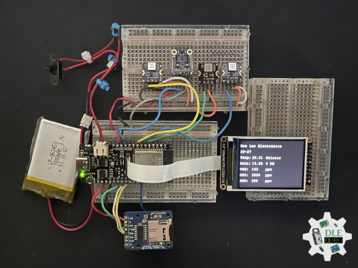
// Don Luc Electronics
screen.setCursor(0, 30);
screen.println("Don Luc Electronics");
// Temperature
screen.setCursor(0, 60);
screen.println( "Temp: " );
screen.setCursor(60, 60);
screen.println( T );
screen.setCursor(130, 60);
screen.println("Celsius");
// Humidity
screen.setCursor(0, 90);
screen.println("Humi: ");
screen.setCursor(60, 90);
screen.println( H );
screen.setCursor(130, 90);
screen.println("% RH");
// MEMS VOC Gas
screen.setCursor(0, 120);
screen.println( "VOC: " );
screen.setCursor(60, 120);
screen.println( iSensorValueVOC );
screen.setCursor(130, 120);
screen.println("ppm");
// MEMS CH4 Gas
screen.setCursor(0, 150);
screen.println( "CH4: " );
screen.setCursor(60, 150);
screen.println( iSensorValueCH4 );
screen.setCursor(130, 150);
screen.println("ppm");
// MEMS Smoke Gas
screen.setCursor(0, 180);
screen.println( "SMO: " );
screen.setCursor(60, 180);
screen.println( iSensorValueSmoke );
screen.setCursor(130, 180);
screen.println("ppm");
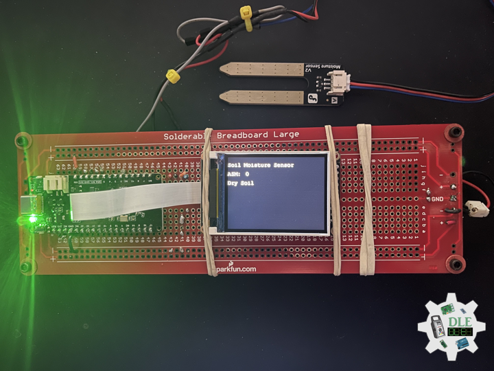
// Gravity: Analog Soil Moisture Sensor
screen.setCursor(0, 210);
screen.println( "ASM: " );
screen.setCursor(60, 210);
screen.println( iSoilMoistureVal );
screen.setCursor(130, 210);
}
getEEPROM.ino
// EEPROM
// isUID EEPROM Unique ID
void isUID() {

  // Is Unit ID
  uid = "";
  for (int x = 0; x < 7; x++)
  {
    uid = uid + char(EEPROM.read(x));
  }

}
getSD.ino
// MicroSD Card
// MicroSD Setup
void isSetupSD() {

    // MicroSD Card
    pinMode( chipSelect , OUTPUT );
    if(!SD.begin( chipSelect )){
        ;
        return;
    }

    uint8_t cardType = SD.cardType();

    // CARD NONE
    if(cardType == CARD_NONE){
        ;
        return;
    }

    // SD Card Type
    if(cardType == CARD_MMC){
        ;
    } else if(cardType == CARD_SD){
        ;
    } else if(cardType == CARD_SDHC){
        ;
    } else {
        ;
    }

    // Size
    uint64_t cardSize = SD.cardSize() / (1024 * 1024);

}
// MicroSD Card
void isSD() {

  zzzzzz = "";

  //DFR|EEPROM Unique ID|Version|
  //Temperature C|% RH|VOC|CH4|Smoke|Soil Moisture|*\r
  zzzzzz = "DFR|" + uid + "|" + sver + "|"
  + String( T ) + "|" + String( H ) + "|"
  + String( iSensorValueVOC ) + "|" + String( iSensorValueCH4 ) + "|"
  + String( iSensorValueSmoke ) + "|" + String( iSoilMoistureVal ) + "|*\r";;

  // msg + 1
  char msg[zzzzzz.length() + 1];

  zzzzzz.toCharArray(msg, zzzzzz.length() + 1);

  // Append File
  appendFile(SD, "/dfrdata.txt", msg );

}
// List Dir
void listDir(fs::FS &fs, const char * dirname, uint8_t levels){

    // List Dir
    dirname;

    File root = fs.open(dirname);

    if(!root){
        return;
    }

    if(!root.isDirectory()){
        return;
    }

    File file = root.openNextFile();

    while(file){
        if(file.isDirectory()){
            file.name();
            if(levels){
                listDir(fs, file.name(), levels -1);
            }
        } else {
            file.name();
            file.size();
        }
        file = root.openNextFile();
    }

}
// Write File
void writeFile(fs::FS &fs, const char * path, const char * message){

    // Write File
    path;

    File file = fs.open(path, FILE_WRITE);

    if(!file){
        return;
    }

    if(file.print(message)){
        ;
    } else {
        ;
    }

    file.close();

}
// Append File
void appendFile(fs::FS &fs, const char * path, const char * message){

    // Append File
    path;

    File file = fs.open(path, FILE_APPEND);

    if(!file){
        return;
    }

    if(file.print(message)){
        ;
    } else {
        ;
    }

    file.close();

}
getSHTC3.ino
// SHTC3 Temperature and Humidity Sensor
// SHTC3
void isSHTC3(){

  // SHTC3 Temperature and Humidity Sensor
  if (sht.readSample()) {

     // Temperature
     T = sht.getTemperature();
     // Humidity
     H = sht.getHumidity();

  }

}
getSmoke.ino
// Smoke
// isSmoke
void isSmoke(){

  // MEMS Smoke Gas
  z = analogRead( iSensorSmoke );
  iSensorValueSmoke = map(x, 1, 4095, 1, 1000);

}
getSoilMoisture.ino
// Gravity: Analog Soil Moisture Sensor
// Soil Moisture
void isSoilMoisture(){

  // Connect Soil Moisture Sensor to Analog 4
  zz = analogRead( iSoilMoisture );

  // iSoilMoistureVal => 0~900 Soil Moisture
  iSoilMoistureVal = map( zz, 0, 4095, 0, 900);

}
getVOC.ino
// MEMS VOC Gas
// is VOC
void isVOC(){

  // MEMS VOC Gas
  x = analogRead( iSensorVOC );
  iSensorValueVOC = map(x, 1, 4095, 1, 500);

}
setup.ino
// Setup
void setup()
{

  // Give display time to power on
  delay(100);

  // EEPROM Size
  EEPROM.begin(EEPROM_SIZE);

  // EEPROM Unique ID
  isUID();

  // Delay
  delay( 100 );

  // Wire
  Wire.begin();

  // Delay
  delay( 100 );

  // SHTC3 Temperature and Humidity Sensor
  sht.init();
  // SHT3x
  sht.setAccuracy(SHTSensor::SHT_ACCURACY_MEDIUM);

  // Delay
  delay( 100 );

  // DFRobot Display 240x320
  screen.begin();

  // Delay
  delay(100);

  // MicroSD Card
  isSetupSD();

  // Initialize the LED Green
  pinMode(iLEDGreen, OUTPUT);

  // iLEDGreen HIGH
  digitalWrite(iLEDGreen, HIGH );

  // DFRobot Display 240x320 - UID
  // Don Luc Electronics
  // Version
  // EEPROM
  isDisplayUID();

  // Delay 5 Second
  delay( 5000 );

}
——
People can contact us: https://www.donluc.com/?page_id=1927
Teacher, Instructor, E-Mentor, R&D and Consulting
- Programming Language
- Single-Board Microcontrollers (PIC, Arduino, Raspberry Pi, Arm, Silicon Labs, Espressif, Etc…)
- IoT
- Wireless (Radio Frequency, Bluetooth, WiFi, Etc…)
- Robotics
- Automation
- Camera and Video Capture Receiver Stationary, Wheel/Tank and Underwater Vehicle
- Unmanned Vehicles Terrestrial and Marine
- Machine Learning
- Artificial Intelligence (AI)
- RTOS
- Sensors, eHealth Sensors, Biosensor, and Biometric
- Research & Development (R & D)
- Consulting
Follow Us
Luc Paquin – Curriculum Vitae – 2024
https://www.donluc.com/luc/
Web: https://www.donluc.com/
Facebook: https://www.facebook.com/neosteam.labs.9/
YouTube: https://www.youtube.com/@thesass2063
Twitter: https://twitter.com/labs_steam
Pinterest: https://www.pinterest.com/NeoSteamLabs/
Instagram: https://www.instagram.com/neosteamlabs/
DFRobot Luc.Paquin: https://edu.dfrobot.com/dashboard/makelogs
Hackster.io: https://www.hackster.io/neosteam-labs
LinkedIn: https://www.linkedin.com/in/jlucpaquin/
Don Luc