——
#DonLucElectronics #DonLuc #Arduino #Christmas #SantaClaus #Display #Elecrow #Project #Patreon #Electronics #Microcontrollers #IoT #Fritzing #Programming #Consultant
——
——
——
——
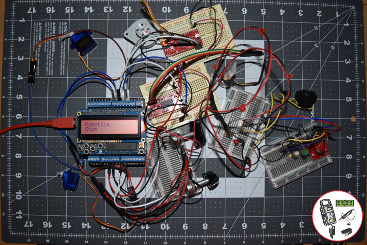
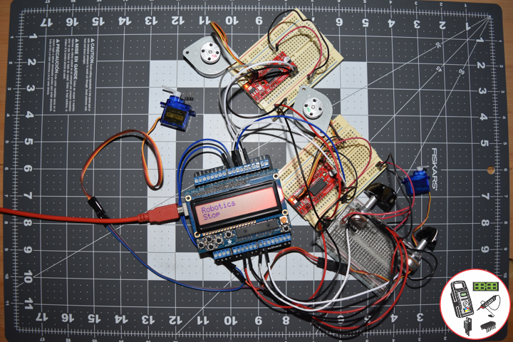
Christmas – Santa Claus
Santa Claus is a legendary figure originating in Western Christian culture who is said to bring gifts during the late evening and overnight hours on Christmas Eve. Christmas elves are said to make the gifts in Santa’s workshop, while flying reindeer pull his sleigh through the air. The popular conception of Santa Claus originates from folklore traditions surrounding the 4th-century Christian bishop Saint Nicholas, the patron saint of children. Saint Nicholas became renowned for his reported generosity and secret gift-giving.
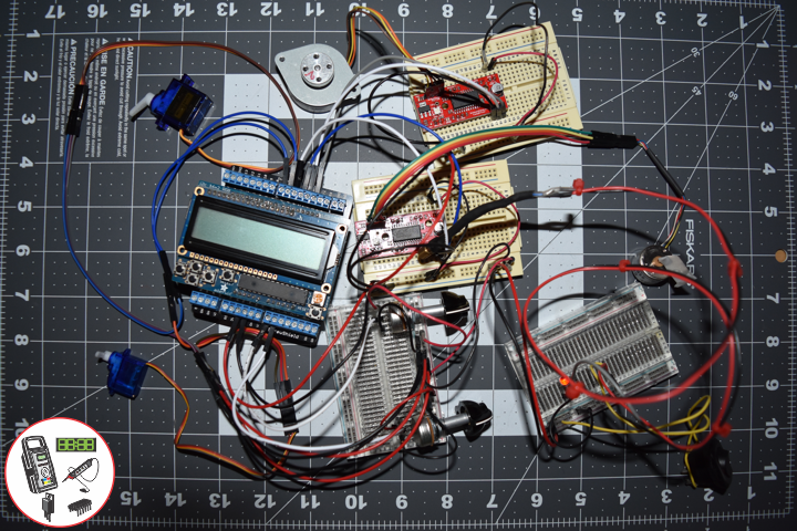
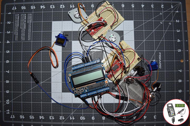
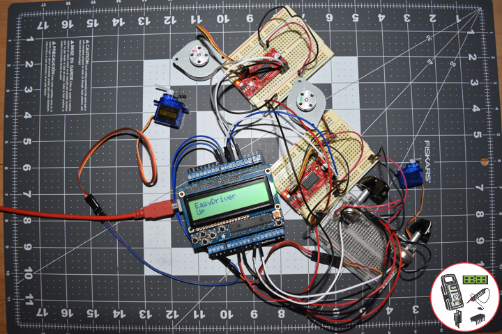
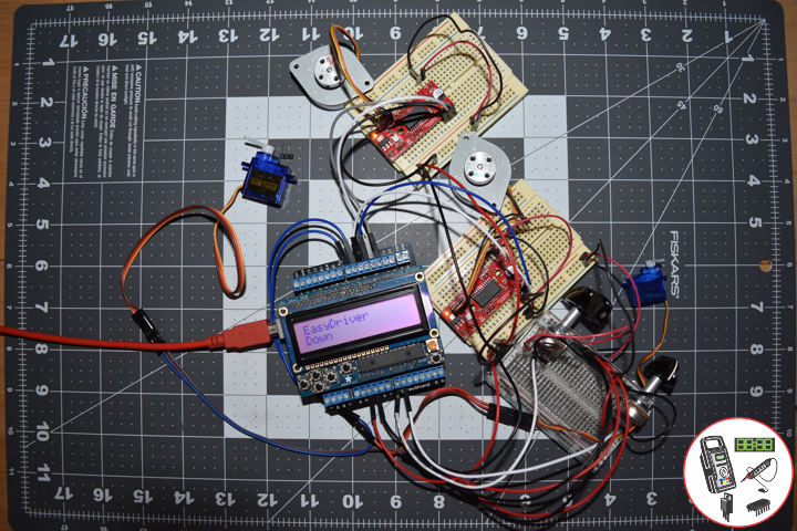
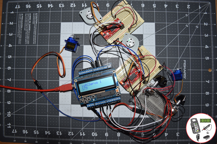
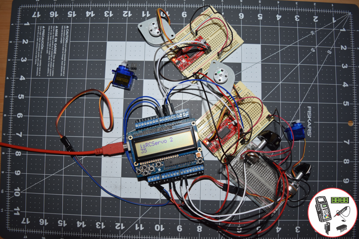
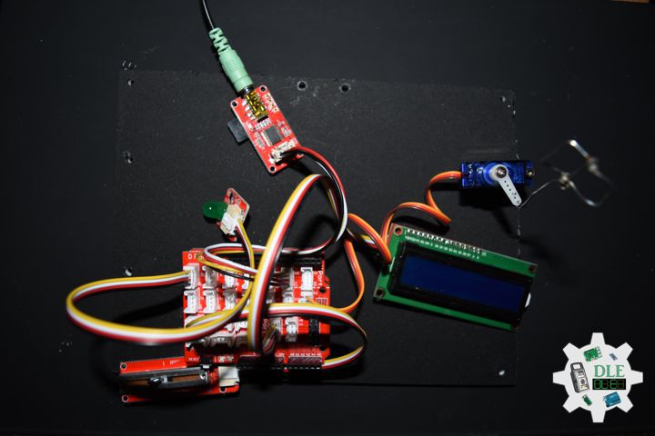
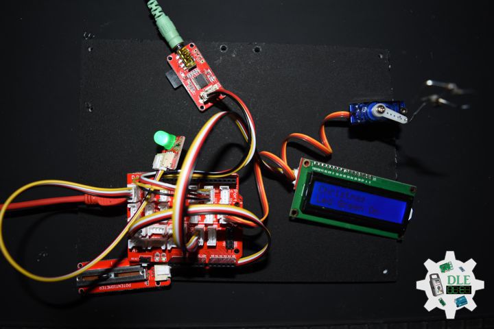
Tracking
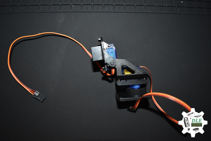
A Servo that to track Santa Claus’ yearly journey.
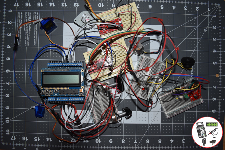
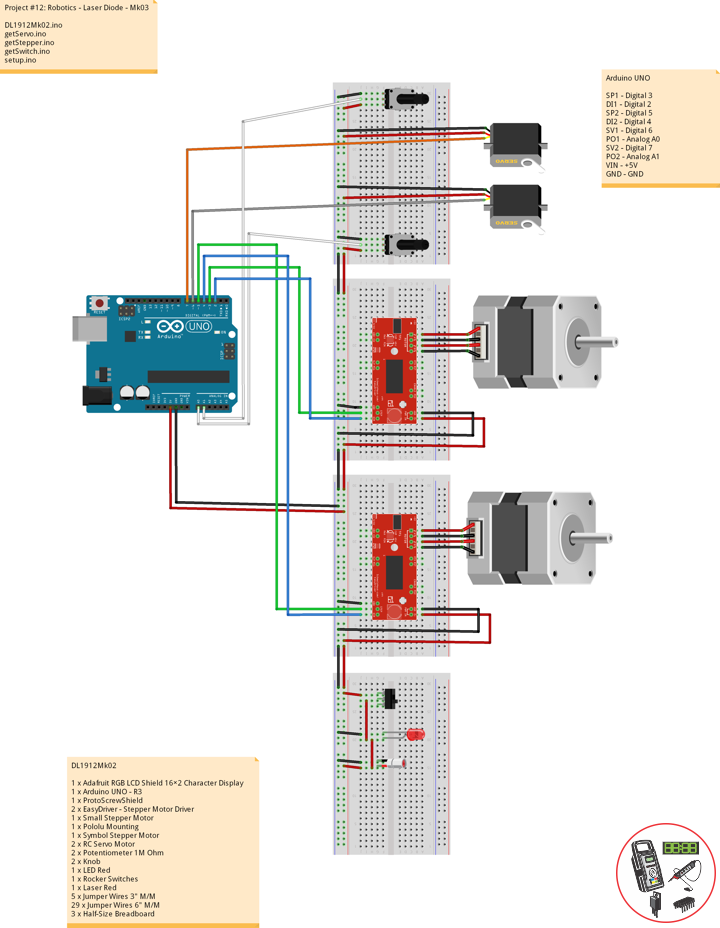
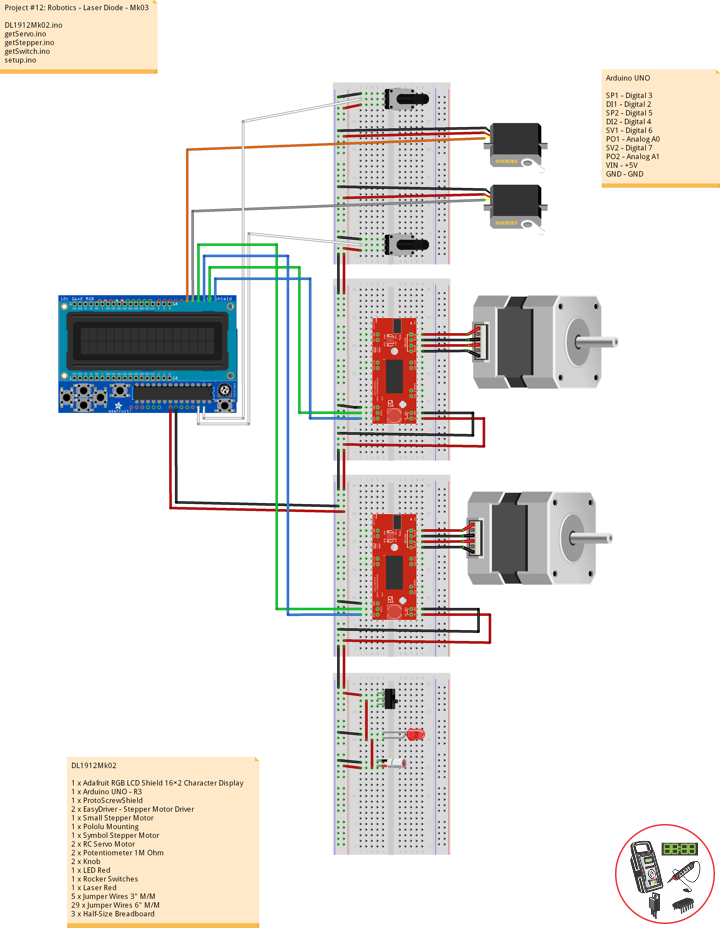
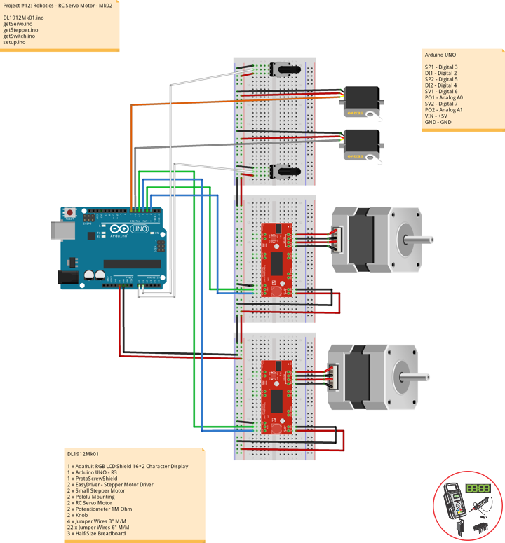
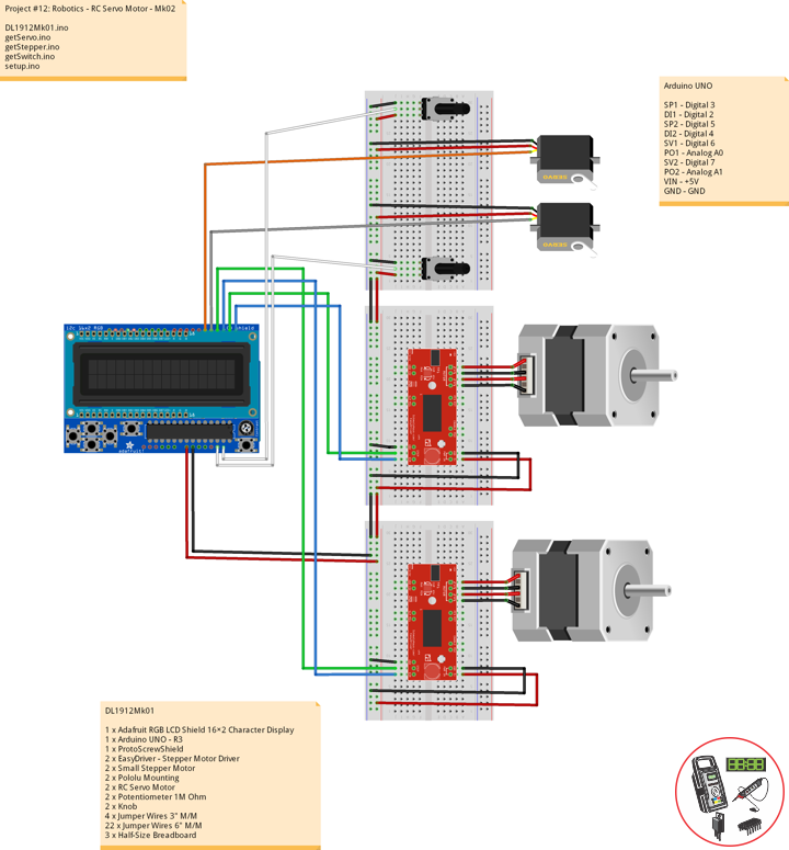
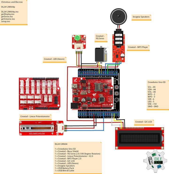
DL2412Mk04
1 x Crowduino Uno-SD
1 x Crowtail – Base Shield
1 x Crowtail – 9G Servo 2.0 (180 Degree Rotation)
1 x Crowtail – Linear Potentiometer – V2.0
1 x Crowtail – MP3 Player 2.0
1 x Crowtail – I2C LCD
1 x Crowtail – LED (Green)
1 x MicroSD 2 GB
1 x Insignia Speakers
1 x USB Battery Pack
1 x USB Mini-B Cable
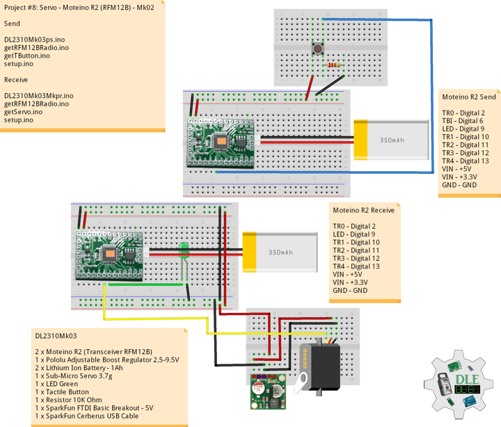
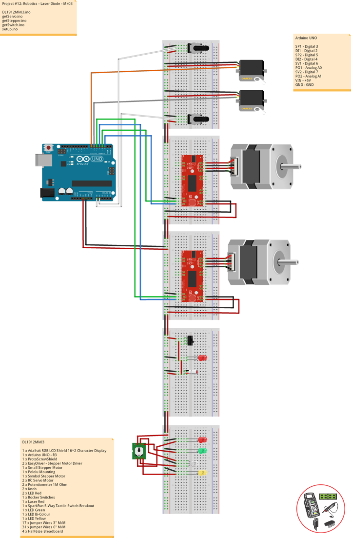
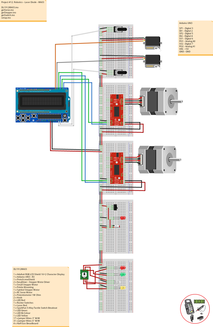
Crowduino Uno-SD
SCL – A5
SDA – A4
VOL – A0
MP3 – 2
MP3 – 3
SER – 6
LEG – 5
VIN – +5V
GND – GND
DL2412Mk04p
DL2412Mk04p.ino
/****** Don Luc Electronics © ******
Software Version Information
Christmas and Elecrow
Christmas
DL2412Mk04p.ino
DL2412Mk04
1 x Crowduino Uno-SD
1 x Crowtail - Base Shield
1 x Crowtail - 9G Servo 2.0 (180 Degree Rotation)
1 x Crowtail - Linear Potentiometer - V2.0
1 x Crowtail - MP3 Player 2.0
1 x Crowtail - I2C LCD
1 x Crowtail - LED (Green)
1 x MicroSD 2 GB
1 x Insignia Speakers
1 x USB Battery Pack
1 x USB Mini-B Cable
*/

// Include the Library Code
// Software Serial
#include <SoftwareSerial.h>
// MP3 Player
#include <MP3Player_KT403A.h>
// Servo
#include<Servo.h>
// Wire
#include <Wire.h>
// Liquid Crystal
#include "LiquidCrystal.h"

// Liquid Crystal
// Connect via i2c
LiquidCrystal lcd(0);

// MP3 Player
SoftwareSerial mp3(2, 3);

// Linear Potentiometer
int LinearPot = A0;
int LinearPotValue = 0;
int z = 0;

// LED Green
int LedGreen =  5;
// LED Green On Off
int zzz = 1;

// Create servo object to control a servo
Servo myservo;
// iServo
int iServo = 6;
// Servo zz
int zz = 0;

// Software Version Information
String sver = "Christmas";

void loop() {

  // Volume
  isVolume();

  // isServo
  isServo();

}
getDisplay.ino
// getDisplay
// Crowtail- I2C LCD
// Display UID
void isDisplayUID(){
// Set up the LCD's number of rows and columns:
lcd.begin(16, 2);
// Print a message to the LCD.
// Cursor
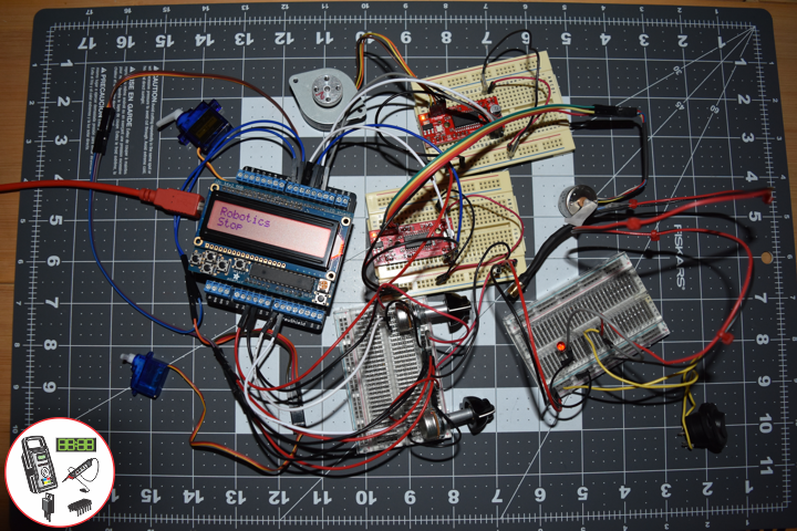
lcd.setCursor(0, 0);
lcd.print("Don Luc Electron");
// Cursor
lcd.setCursor(0, 1);
// Print a message to the LCD.
lcd.print( sver );
}
// isDisplay Green On
void isDisplayGOn(){
// Print a message to the LCD
// Clear
lcd.clear();
// Cursor
lcd.setCursor(0, 0);
lcd.print("Christmas");
// Cursor
lcd.setCursor(0, 1);
// Print a message to the LCD
lcd.print( "Led Green On" );
}
// isDisplay Green Off
void isDisplayGOff(){
// Print a message to the LCD
// Clear
lcd.clear();
// Cursor
lcd.setCursor(0, 0);
lcd.print("Christmas");
// Cursor
lcd.setCursor(0, 1);
// Print a message to the LCD
lcd.print( "Led Green Off" );
}
getServo.ino
// Servo
// isServo
void isServo(){

  // Servo zz
  zz -= 1;

  if ( zz == 0 ) {

    // Servo zz
    zz = 100;

    // LED Green On Off
    if ( zzz == 1 ) { // Led Green On

      // Led Green On
      Serial.println("Led Green On");
      digitalWrite(LedGreen, HIGH);
      // Servo Write
      myservo.write(-90);
      // isDisplay Green On
      isDisplayGOn();
      zzz = 2;

    } else if ( zzz == 2 ) { // Led Green Off

       // Led Green Off
      Serial.println("Led Green Off");
      digitalWrite(LedGreen, LOW);
      // Servo Write
      myservo.write(90);
      // isDisplay Green Off
      isDisplayGOff();
      zzz = 1;

    }

 }

}
getVolume.ino
// Volume
// is Volume
void isVolume(){
// Linear Potentiometer
// Allowable Volume values are 0 to 30
LinearPotValue = analogRead( LinearPot );
z = map(LinearPotValue, 0, 1023, 0, 30);
// Volume
SetVolume(z);
}
setup.ino
// Setup
void setup()
{

  // Delay
  delay(100);

  // Initialize the LED Green
  pinMode(LedGreen, OUTPUT);

  // MP3 Player
  // MP3 Player module is configured to talk at 9600 bauds
  mp3.begin(9600);

  // Small delay
  delay(100);

  // We configure the library to use the SD card
  SelectPlayerDevice(0x02);

  // Index of the song between 0 and 65535
  // Play Loop
  PlayLoop();

  // Attaches the iServo
  myservo.attach(iServo);

  // Servo zz
  zz = 101;

  // Display UID
  isDisplayUID();

  // Delay 5 Second
  delay( 5000 );

}
——
People can contact us: https://www.donluc.com/?page_id=1927
Electronics, IoT, Teacher, Instructor, R&D and Consulting
- Programming Language
- Single-Board Microcontrollers (PIC, Arduino, Raspberry Pi, Arm, Silicon Labs, Espressif, Etc…)
- IoT
- Wireless (Radio Frequency, Bluetooth, WiFi, Etc…)
- Robotics
- Automation
- Camera and Video Capture Receiver Stationary, Wheel/Tank and Underwater Vehicle
- Unmanned Vehicles Terrestrial and Marine
- Machine Learning
- Artificial Intelligence (AI)
- RTOS
- Sensors, eHealth Sensors, Biosensor, and Biometric
- Research & Development (R & D)
- Consulting
Follow Us
Luc Paquin – Curriculum Vitae – 2024
https://www.donluc.com/luc/
Web: https://www.donluc.com/
Facebook: https://www.facebook.com/neosteam.labs.9/
YouTube: https://www.youtube.com/@thesass2063
Twitter: https://twitter.com/labs_steam
Pinterest: https://www.pinterest.com/NeoSteamLabs/
Instagram: https://www.instagram.com/neosteamlabs/
Patreon: https://patreon.com/DonLucElectronics59
DFRobot: https://learn.dfrobot.com/user-10186.html
Hackster.io: https://www.hackster.io/neosteam-labs
Elecrow: https://www.elecrow.com/share/sharepj/center/no/760816d385ebb1edc0732fd873bfbf13
TikTok: https://www.tiktok.com/@luc.paquin8
Twitch: https://www.twitch.tv/lucpaquin
LinkedIn: https://www.linkedin.com/in/jlucpaquin/
Don Luc