——
#DonLuc #Environment #ESP32 #MQ #GPS #EMF #PIR #SparkFun #Adafruit #Pololu #Fritzing #Programming #Arduino #Consultant #Electronics #Microcontrollers #Vlog #Aphasia
——
——
——
——
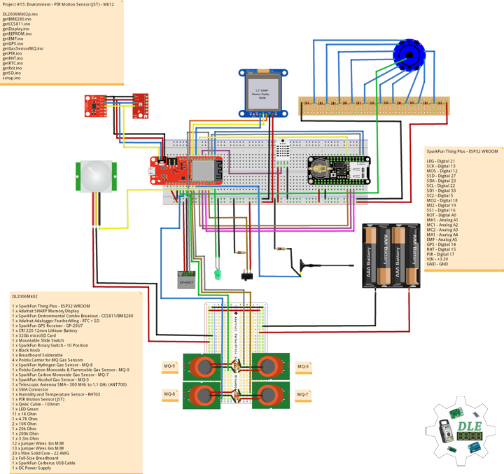
PIR Motion Sensor (JST)
SparkFun Item: SEN-13285
This is a simple to use motion sensor. Power it up and wait 1-2 seconds for the sensor to get a snapshot of the still room. If anything moves after that period, the ‘alarm’ pin will go low. The alarm pin is an open collector meaning you will need a pull up resistor on the alarm pin. The open drain setup allows multiple motion sensors to be connected on a single input pin. If any of the motion sensors go off, the input pin will be pulled low.
We’ve finally updated the connector! Gone is the old “odd” connector, now you will find a common 3-pin JST! This makes the PIR Sensor much more accessible for whatever your project may need. Red = Power, White = Ground, and Black = Alarm.
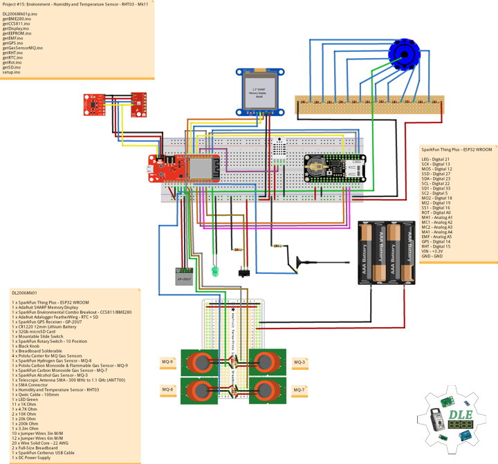
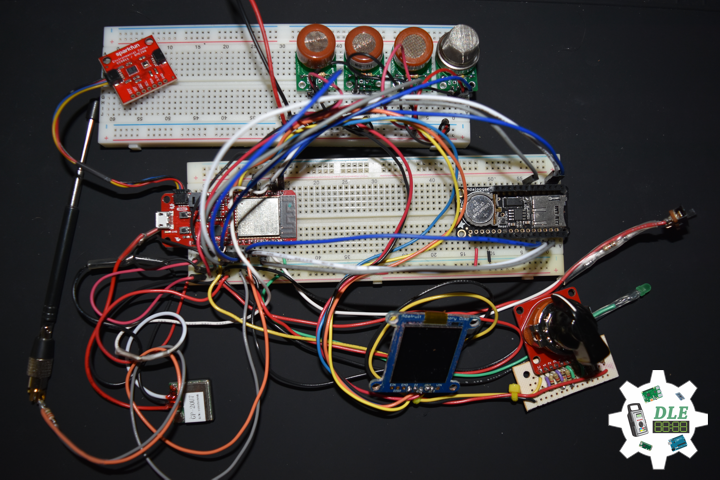
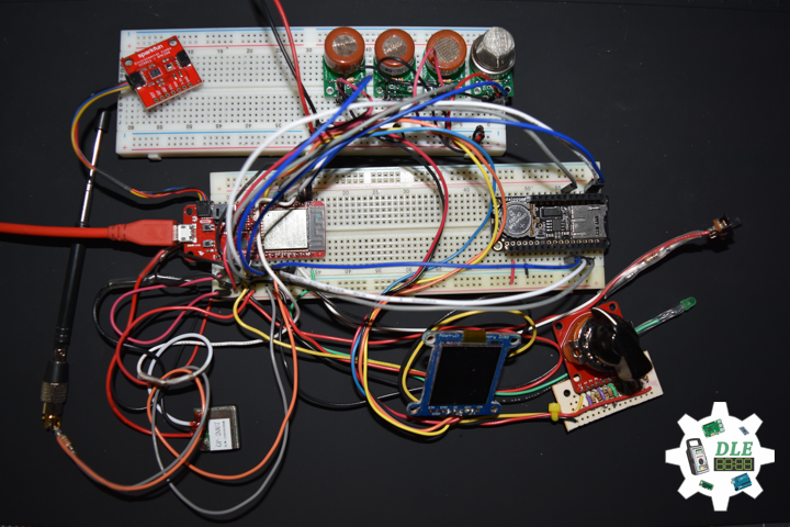
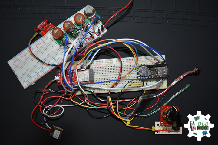
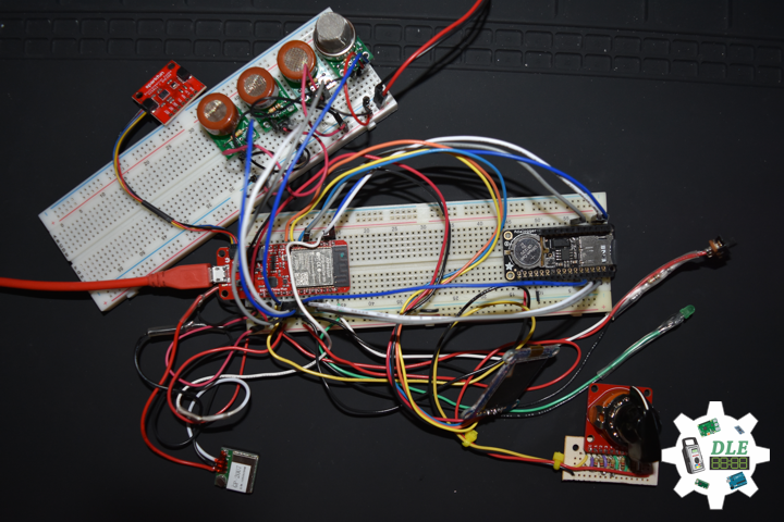
DL2006Mk02
1 x SparkFun Thing Plus – ESP32 WROOM
1 x Adafruit SHARP Memory Display
1 x SparkFun Environmental Combo Breakout – CCS811/BME280
1 x Adafruit Adalogger FeatherWing – RTC + SD
1 x SparkFun GPS Receiver – GP-20U7
1 x CR1220 12mm Lithium Battery
1 x 32Gb microSD Card
1 x Mountable Slide Switch
1 x SparkFun Rotary Switch – 10 Position
1 x Black Knob
1 x Breadboard Solderable
4 x Pololu Carrier for MQ Gas Sensors
1 x SparkFun Hydrogen Gas Sensor – MQ-8
1 x Pololu Carbon Monoxide & Flammable Gas Sensor – MQ-9
1 x SparkFun Carbon Monoxide Gas Sensor – MQ-7
1 x SparkFun Alcohol Gas Sensor – MQ-3
1 x Telescopic Antenna SMA – 300 MHz to 1.1 GHz (ANT700)
1 x SMA Connector
1 x Humidity and Temperature Sensor – RHT03
1 x PIR Motion Sensor (JST)
1 x Qwiic Cable – 100mm
1 x LED Green
11 x 1K Ohm
1 x 4.7K Ohm
2 x 10K Ohm
1 x 20k Ohm
1 x 200k Ohm
1 x 3.3m Ohm
12 x Jumper Wires 3in M/M
13 x Jumper Wires 6in M/M
20 x Wire Solid Core – 22 AWG
2 x Full-Size Breadboard
1 x SparkFun Cerberus USB Cable
1 x DC Power Supply
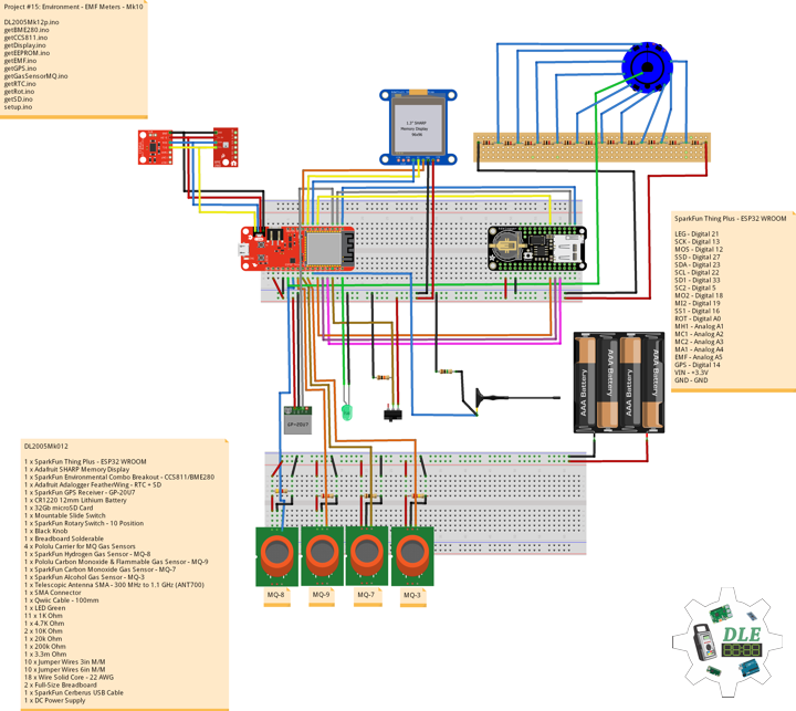
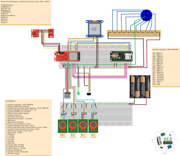
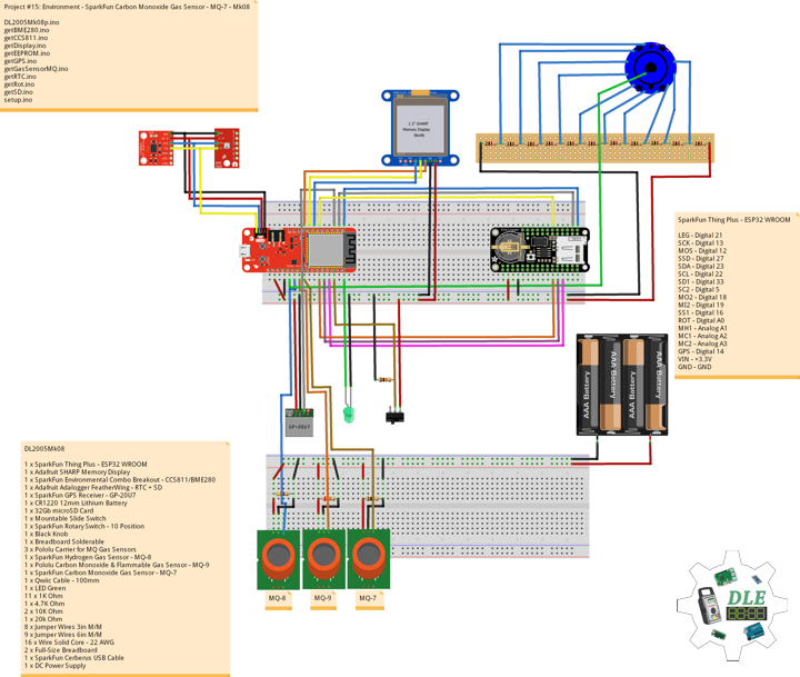
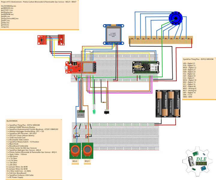
SparkFun Thing Plus – ESP32 WROOM
LEG – Digital 21
SCK – Digital 13
MOS – Digital 12
SSD – Digital 27
SDA – Digital 23
SCL – Digital 22
SD1 – Digital 33
SC2 – Digital 5
MO2 – Digital 18
MI2 – Digital 19
SS1 – Digital 16
ROT – Analog A1
MH1 – Analog A0
MC1 – Analog A2
MC2 – Analog A3
MA1 – Analog A4
EMF – Analog A5
GPS – Digital 14
RHT – Digital 15
PIR – Digital 17
VIN – +3.3V
GND – GND
DL2006Mk02p.ino
// ***** Don Luc Electronics © *****
// Software Version Information
// Project #15: Environment - PIR Motion Sensor (JST) - Mk12
// 06-02
// DL2006Mk02p.ino 15-12
// EEPROM with Unique ID
// 1 x SparkFun Thing Plus - ESP32 WROOM
// 1 x Adafruit SHARP Memory Display
// 1 x SparkFun Environmental Combo Breakout - CCS811/BME280
// 1 x Adafruit Adalogger FeatherWing - RTC + SD
// 1 x SparkFun GPS Receiver - GP-20U7
// 1 x CR1220 12mm Lithium Battery
// 1 x 32Gb microSD Card
// 1 x Mountable Slide Switch
// 1 x SparkFun Rotary Switch - 10 Position
// 1 x Black Knob
// 1 x Breadboard Solderable
// 4 x Pololu Carrier for MQ Gas Sensors
// 1 x SparkFun Hydrogen Gas Sensor - MQ-8
// 1 x Pololu Carbon Monoxide & Flammable Gas Sensor - MQ-9
// 1 x SparkFun Carbon Monoxide Gas Sensor - MQ-7
// 1 x SparkFun Alcohol Gas Sensor - MQ-3
// 1 x Telescopic Antenna SMA - 300 MHz to 1.1 GHz (ANT700)
// 1 x SMA Connector
// 1 x Humidity and Temperature Sensor - RHT03
// 1 x PIR Motion Sensor (JST)
// 1 x Qwiic Cable - 100mm
// 1 x LED Green
// 11 x 1K Ohm
// 1 x 4.7K Ohm
// 2 x 10K Ohm
// 1 x 20k Ohm
// 1 x 200k Ohm
// 1 x 3.3m Ohm
// 12 x Jumper Wires 3in M/M
// 13 x Jumper Wires 6in M/M
// 20 x Wire Solid Core - 22 AWG
// 2 x Full-Size Breadboard
// 1 x SparkFun Cerberus USB Cable
// 1 x DC Power Supply

// Include the Library Code
// EEPROM Library to Read and Write EEPROM with Unique ID for Unit
#include "EEPROM.h"
// Wire
#include <Wire.h>
// SHARP Memory Display
#include <Adafruit_SharpMem.h>
#include <Adafruit_GFX.h>
// SparkFun CCS811 - eCO2 & tVOC
#include <SparkFunCCS811.h>
// SparkFun BME280 - Humidity, Temperature, Altitude and Barometric Pressure
#include <SparkFunBME280.h>
// Date and Time
#include "RTClib.h"
// SD Card
#include "FS.h"
#include "SD.h"
#include "SPI.h"
// GPS Receiver
#include <TinyGPS++.h>
// Hardware Serial
#include <HardwareSerial.h>
// RHT Humidity and Temperature Sensor
#include <SparkFun_RHT03.h>

// LED Green
int iLEDGreen = 21;

// SHARP Memory Display
// any pins can be used
#define SHARP_SCK  13
#define SHARP_MOSI 12
#define SHARP_SS   27
// Set the size of the display here - 144x168
Adafruit_SharpMem display(SHARP_SCK, SHARP_MOSI, SHARP_SS, 144, 168);
// The currently-available SHARP Memory Display (144x168 pixels)
// requires > 4K of microcontroller RAM; it WILL NOT WORK on Arduino Uno
// or other <4K "classic" devices!
#define BLACK 0
#define WHITE 1
// 1/2 of lesser of display width or height
int minorHalfSize;

// SparkFun CCS811 - eCO2 & tVOC
// Default I2C Address
#define CCS811_ADDR 0x5B
CCS811 myCCS811(CCS811_ADDR);
float CCS811CO2 = 0;
float CCS811TVOC = 0;

// SparkFun BME280 - Humidity, Temperature, Altitude and Barometric Pressure
BME280 myBME280;
float BMEtempC = 0;
float BMEhumid = 0;
float BMEaltitudeM = 0;
float BMEpressure = 0;

// Date and Time
// PCF8523 Precision RTC
RTC_PCF8523 rtc;
String dateRTC = "";
String timeRTC = "";

// microSD Card
const int chipSelect = 33;
String zzzzzz = "";

// Mountable Slide Switch
int iSS1 = 16;
// State
int iSS1State = 0;

// ESP32 HardwareSerial
HardwareSerial tGPS(2);

// GPS Receiver
#define gpsRXPIN 14
// This one is unused and doesnt have a conection
#define gpsTXPIN 32
// The TinyGPS++ object
TinyGPSPlus gps;
float TargetLat;
float TargetLon;
int GPSStatus = 0;

// Rotary Switch - 10 Position
// Number 1 => 10
int iRotNum = A0;
// iRotVal - Value
int iRotVal = 0;
// Number
int z = 0;
int x = 0;

// Gas Sensors MQ
// Hydrogen Gas Sensor - MQ-8
int iMQ8 = A1;
int iMQ8Raw = 0;
int iMQ8ppm = 0;
// Two points are taken from the curve in datasheet
// With these two points, a line is formed which is "approximately equivalent" to the original curve
float H2Curve[3] = {2.3, 0.93,-1.44};
// Carbon Monoxide & Flammable Gas Sensor - MQ-9
int iMQ9 = A2;
int iMQ9Raw = 0;
int iMQ9ppm = 0;
// Carbon Monoxide Gas Sensor - MQ-7
int iMQ7 = A3;
int iMQ7Raw = 0;
int iMQ7ppm = 0;
// Alcohol Gas Sensor - MQ-3
int iMQ3 = A4;
int iMQ3Raw = 0;
int iMQ3ppm = 0;

// EMF Meter (Single Axis)
int iEMF = A5;
// Raise this number to increase data smoothing
#define NUMREADINGS 15
// Raise this number to decrease sensitivity (up to 1023 max)
int senseLimit = 15;
// EMF Value
int valEMF = 0;
// Readings from the analog input
int readings[ NUMREADINGS ];
// Index of the current reading
int indexEMF = 0;
// Running total
int totalEMF = 0;
// Final average of the probe reading
int averageEMF = 0;
int iEMFDis = 0;
int iEMFRect = 0;

// RHT Humidity and Temperature Sensor
// RHT03 data pin Digital 15
const int RHT03_DATA_PIN = 15;
// This creates a RTH03 object, which we'll use to interact with the sensor
RHT03 rht;
float latestHumidity;
float latestTempC;
float latestTempF;

// PIR Motion
// Motion detector
const int iMotion = 17;
// Proximity
int proximity = LOW;
String Det = "";

// Software Version Information
String sver = "15-12";
// EEPROM Unique ID Information
#define EEPROM_SIZE 64
String uid = "";

void loop() {

  // Receives NEMA data from GPS receiver
  isGPS();

  // Date and Time
  isRTC();

  // SparkFun BME280 - Humidity, Temperature, Altitude and Barometric Pressure
  isBME280();

  // SparkFun CCS811 - eCO2 & tVOC
  isCCS811();

  // Gas Sensors MQ
  isGasSensor();

  // EMF Meter (Single Axis)
  isEMF();

  // RHT03 Humidity and Temperature Sensor
  isRHT03();

  // isPIR Motion
  isPIR();

  // Rotary Switch
  isRot();

  // Slide Switch
  // Read the state of the iSS1 value
  iSS1State = digitalRead(iSS1);

  // If it is the Slide Switch State is HIGH
  if (iSS1State == HIGH) {

    // iLEDGreen
    digitalWrite(iLEDGreen,  HIGH );

    // microSD Card
    isSD();

  } else {

    // iLEDGreen
    digitalWrite(iLEDGreen,  LOW );

  }

  delay( 1000 );

}
getBME280.ino
// SparkFun BME280 - Humidity, Temperature, Altitude and Barometric Pressure
// isBME280 - Temperature, Humidity, Altitude and Barometric Pressure
void isBME280(){

  // Temperature Celsius
  BMEtempC = myBME280.readTempC();
  // Humidity
  BMEhumid = myBME280.readFloatHumidity();
  // Altitude Meters
  BMEaltitudeM = (myBME280.readFloatAltitudeMeters(), 2);
  // Barometric Pressure
  BMEpressure = myBME280.readFloatPressure();

}
getCCS811.ino
// CCS811 - eCO2 & tVOC
// isCCS811 - eCO2 & tVOC
void isCCS811(){

  // This sends the temperature & humidity data to the CCS811
  myCCS811.setEnvironmentalData(BMEhumid, BMEtempC);

  // Calling this function updates the global tVOC and eCO2 variables
  myCCS811.readAlgorithmResults();

  // eCO2 Concentration
  CCS811CO2 = myCCS811.getCO2();

  // tVOC Concentration
  CCS811TVOC = myCCS811.getTVOC();

}
getDisplay.ino
// Display
// SHARP Memory Display - UID
void isDisplayUID() {
// Text Display
// Clear Display
display.clearDisplay();
display.setRotation(4);
display.setTextSize(3);
display.setTextColor(BLACK);
// Don Luc Electronics
display.setCursor(0,10);
display.println( "Don Luc" );
display.setTextSize(2);
display.setCursor(0,40);
display.println( "Electronics" );
// Version
display.setTextSize(3);
display.setCursor(0,70);
display.println( "Version" );
display.setTextSize(2);
display.setCursor(0,100);
display.println( sver );
// EEPROM Unique ID
display.setTextSize(1);
display.setCursor(0,130);
display.println( "EEPROM Unique ID" );
display.setTextSize(2);
display.setCursor(0,145);
display.println( uid );
// Refresh
display.refresh();
delay( 100 );
}
// Display Environmental
void isDisplayEnvironmental(){
// Text Display Environmental
// Clear Display
display.clearDisplay();
display.setRotation(4);
display.setTextSize(1);
display.setTextColor(BLACK);
// Temperature Celsius
display.setCursor(0,0);
display.println( "Temperature Celsius" );
display.setCursor(0,10);
display.print( BMEtempC );
display.println( " C" );
// Humidity
display.setCursor(0,20);
display.println( "Humidity" );
display.setCursor(0,30);
display.print( BMEhumid );
display.println( "%" );
// Altitude Meters
display.setCursor(0,40);
display.println( "Altitude Meters" );
display.setCursor(0,50);
display.print( BMEaltitudeM );
display.println( " m" );
// Pressure
display.setCursor(0,60);
display.println( "Barometric Pressure" );
display.setCursor(0,70);
display.print( BMEpressure );
display.println( " Pa" );
// eCO2 Concentration
display.setCursor(0,80);
display.println( "eCO2 Concentration" );
display.setCursor(0,90);
display.print( CCS811CO2 );
display.println( " ppm" );
// tVOC Concentration
display.setCursor(0,100);
display.println( "tVOC Concentration" );
display.setCursor(0,110);
display.print( CCS811TVOC );
display.println( " ppb" );
// Date
display.setCursor(0,120);
display.println( dateRTC );
// Time
display.setCursor(0,130);
display.println( timeRTC );
// GPS Status
display.setCursor(0,140);
display.println( GPSStatus );
// Target Latitude
display.setCursor(0,150);
display.println( TargetLat );
// Target Longitude
display.setCursor(0,160);
display.println( TargetLon );
// Refresh
display.refresh();
delay( 100 );
}
// Display Date
void isDisplayDate() {
// Text Display Date
// Clear Display
display.clearDisplay();
display.setRotation(4);
display.setTextSize(2);
display.setTextColor(BLACK);
// Date
display.setCursor(0,5);
display.println( dateRTC );
// Time
display.setCursor(0,30);
display.println( timeRTC );
// GPS Status
display.setCursor(0,60);
display.print( "GPS: " );
display.println( GPSStatus );
// Target Latitude
display.setCursor(0,80);
display.println( "Latitude" );
display.setCursor(0,100);
display.println( TargetLat );
// Target Longitude
display.setCursor(0,120);
display.println( "Longitude" );
display.setCursor(0,140);
display.println( TargetLon );
// Refresh
display.refresh();
delay( 100 );
}
// Display BME280
void isDisplayBME280() {
// Text Display BME280
// Clear Display
display.clearDisplay();
display.setRotation(4);
display.setTextSize(2);
display.setTextColor(BLACK);
// Temperature Celsius
display.setCursor(0,10);
display.println( "Temperature" );
display.setCursor(0,30);
display.print( BMEtempC );
display.println( " C" );
// Humidity
display.setCursor(0,50);
display.println( "Humidity" );
display.setCursor(0,70);
display.print( BMEhumid );
display.println( "%" );
// Altitude Meters
display.setCursor(0,90);
display.println( "Altitude M" );
display.setCursor(0,110);
display.print( BMEaltitudeM );
display.println( " m" );
// Pressure
display.setCursor(0,130);
display.println( "Barometric" );
display.setCursor(0,150);
display.print( BMEpressure );
display.println( "Pa" );
// Refresh
display.refresh();
delay( 100 );
}
// Display CCS811 - eCO2 & tVOC
void isDisplayCCS811() {
// Text Display CCS811
// Clear Display
display.clearDisplay();
display.setRotation(4);
display.setTextSize(2);
display.setTextColor(BLACK);
// eCO2 Concentration
display.setCursor(0,10);
display.println( "eCO2" );
display.setCursor(0,30);
display.print( CCS811CO2 );
display.println( " ppm" );
// tVOC Concentration
display.setCursor(0,60);
display.println( "tVOC" );
display.setCursor(0,80);
display.print( CCS811TVOC );
display.println( " ppb" );
// Refresh
display.refresh();
delay( 100 );
}
// Display Gas Sensors MQ
void isDisplayMQ() {
// Text Display MQ
// Clear Display
display.clearDisplay();
display.setRotation(4);
display.setTextSize(2);
display.setTextColor(BLACK);
// Gas Sensors MQ
display.setCursor(0,10);
display.println( "Gas H2 MQ8" );
display.setCursor(0,30);
display.print( iMQ8ppm );
display.println( " ppm" );
display.setCursor(0,50);
display.println( "Gas CO MQ9" );
display.setCursor(0,70);
display.print( iMQ9ppm );
display.println( " ppm" );
display.setCursor(0,90);
display.println( "Gas CO MQ7" );
display.setCursor(0,110);
display.print( iMQ7ppm );
display.println( " ppm" );
display.setCursor(0,130);
display.println( "BAC MQ3" );
display.setCursor(0,150);
display.print( iMQ3ppm );
display.println( "%" );
// Refresh
display.refresh();
delay( 100 );
}
// EMF Meter (Single Axis)
void isDisplayEMF() {
// Text Display EMF Meter
// Clear Display
display.clearDisplay();
display.setRotation(4);
display.setTextSize(2);
display.setTextColor(BLACK);
// EMF Meter
display.setCursor(0,10);
display.println( "EMF Meter" );
display.setCursor(0,30);
display.print( "EMF: " );
display.println( averageEMF );
display.setCursor(0,50);
display.println( iEMFDis );
display.setCursor(0,70);
display.setTextSize(1);
display.println( "0 1 2 3 4 5 6 7 8 9 10" );
display.setCursor(0,90);
display.drawRect(0, 90, iEMFRect , display.height(), BLACK);
display.fillRect(0, 90, iEMFRect , display.height(), BLACK);
// Refresh
display.refresh();
delay( 100 );
}
// Display PIR Motion
void isDisplayPIR() {
// Text Display PIR
// Clear Display
display.clearDisplay();
display.setRotation(4);
display.setTextSize(2);
display.setTextColor(BLACK);
// PIR Motion
display.setCursor(0,10);
display.println( "PIR Motion" );
display.setCursor(0,30);
display.println( Det );
// Refresh
display.refresh();
delay( 100 );
}
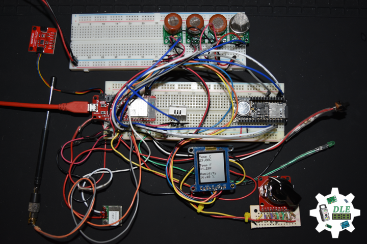
// Display RHT
void isDisplayRHT() {
// Text Display RHT
// Clear Display
display.clearDisplay();
display.setRotation(4);
display.setTextSize(2);
display.setTextColor(BLACK);
// Temperature
display.setCursor(0,10);
display.println( "Temp C" );
display.setCursor(0,30);
display.print( latestTempC );
display.println( "C" );
// Temp F
display.setCursor(0,60);
display.println( "Temp F" );
display.setCursor(0,80);
display.print( latestTempF );
display.println( "F" );
// Humidity
display.setCursor(0,110);
display.println( "Humidity" );
display.setCursor(0,130);
display.print( latestHumidity );
display.println( " %" );
// Refresh
display.refresh();
delay( 100 );
}
// Display Z
void isDisplayZ() {
// Text Display Z
// Clear Display
display.clearDisplay();
display.setRotation(4);
display.setTextSize(3);
display.setTextColor(BLACK);
// Z
display.setCursor(0,10);
display.print( "Z: " );
display.println( z );
// Refresh
display.refresh();
delay( 100 );
}
getEEPROM.ino
// EEPROM
// isUID EEPROM Unique ID
void isUID()
{

  // Is Unit ID
  uid = "";
  for (int x = 0; x < 5; x++)
  {
    uid = uid + char(EEPROM.read(x));
  }

}
getEMF.ino
// EMF Meter (Single Axis)
// Setup EMF Meter
void isSetupEMF() {

  // EMF Meter (Single Axis)
  pinMode( iEMF, OUTPUT );
  for (int i = 0; i < NUMREADINGS; i++){
    readings[ i ] = 0;     // Initialize all the readings to 0
  }

}
// EMF Meter
void isEMF() {

  // Probe EMF Meter
  // Take a reading from the probe
  valEMF = analogRead( iEMF );

  // If the reading isn't zero, proceed
  if( valEMF >= 1 ){

    // Turn any reading higher than the senseLimit value into the senseLimit value
    valEMF = constrain( valEMF, 1, senseLimit );
    // Remap the constrained value within a 1 to 1023 range
    valEMF = map( valEMF, 1, senseLimit, 1, 1023 );

    // Subtract the last reading
    totalEMF -= readings[ indexEMF ];
    // Read from the sensor
    readings[ indexEMF ] = valEMF;
    // Add the reading to the total
    totalEMF += readings[ indexEMF ];
    // Advance to the next index
    indexEMF = ( indexEMF + 1 );

    // If we're at the end of the array...
    if ( indexEMF >= NUMREADINGS ) {

      // Wrap around to the beginning
      indexEMF = 0;

    }

    // Calculate the average
    averageEMF = totalEMF / NUMREADINGS;

    iEMFDis = averageEMF;
    iEMFRect = map( averageEMF, 1, 1023, 1, 144 );

  }
  else
  {

    averageEMF = 0;

  }

}
getGPS.ino
// GPS Receiver
// Setup GPS
void setupGPS() {

  // Setup GPS
  tGPS.begin(  9600 , SERIAL_8N1, gpsRXPIN, gpsTXPIN );

}
// isGPS
void isGPS(){

  // Receives NEMA data from GPS receiver
  // This sketch displays information every time a new sentence is correctly encoded.
  while ( tGPS.available() > 0)
    if (gps.encode( tGPS.read() ))
    {
     displayInfo();
    }

  if (millis() > 5000 && gps.charsProcessed() < 10)
  {
    while(true);
  }

}
// GPS Vector Pointer Target
void displayInfo(){

  // Location
  if (gps.location.isValid())
  {

    TargetLat = gps.location.lat();
    TargetLon = gps.location.lng();
    GPSStatus = 2;

  }
  else
  {

    GPSStatus = 0;

  }

}
getGasSensorMQ.ino
// Gas Sensors MQ
// Gas Sensor
void isGasSensor() {

  // Read in analog value from each gas sensors

  // Hydrogen Gas Sensor - MQ-8
  iMQ8Raw = analogRead( iMQ8 );

  // Carbon Monoxide & Flammable Gas Sensor - MQ-9
  iMQ9Raw = analogRead( iMQ9 );

  // Carbon Monoxide Gas Sensor - MQ-7
  iMQ7Raw = analogRead( iMQ7 );

  // Alcohol Gas Sensor - MQ-3
  iMQ3Raw = analogRead( iMQ3 );

  // Caclulate the PPM of each gas sensors

  // Hydrogen Gas Sensor - MQ-8
  iMQ8ppm = isMQ8( iMQ8Raw );

  // Carbon Monoxide & Flammable Gas Sensor - MQ-9
  iMQ9ppm = isMQ9( iMQ9Raw );

  // Carbon Monoxide Gas Sensor - MQ-7
  iMQ7ppm = isMQ7( iMQ7Raw );

  // Alcohol Gas Sensor - MQ-3
  iMQ3ppm = isMQ3( iMQ3Raw );

}
// Hydrogen Gas Sensor - MQ-8 - PPM
int isMQ8(double rawValue) {

  // RvRo
  double RvRo = rawValue * (3.3 / 1023);

  return (pow(4.7,( ((log(RvRo)-H2Curve[1])/H2Curve[2]) + H2Curve[0])));

}
// Carbon Monoxide & Flammable Gas Sensor - MQ-9
int isMQ9(double rawValue) {

  double RvRo = rawValue * 3.3 / 4095;

  double ppm = 3.027*exp(1.0698*( RvRo ));
  return ppm;

}
// Carbon Monoxide Gas Sensor - MQ-7
int isMQ7(double rawValue) {

  double RvRo = rawValue * 3.3 / 4095;

  double ppm = 3.027*exp(1.0698*( RvRo ));
  return ppm;

}
// Alcohol Gas Sensor - MQ-3
int isMQ3(double rawValue) {

  double RvRo = rawValue * 3.3 / 4095;

  double bac = RvRo * 0.21;
  return bac;

}
getPIR.ino
// PIR Motion
// Setup PIR
void setupPIR() {

  // Setup PIR Montion
  pinMode(iMotion, INPUT_PULLUP);

}
// isPIR Motion
void isPIR() {

  // Proximity
  proximity = digitalRead(iMotion);
  if (proximity == LOW)
  {

    // PIR Motion Sensor's LOW, Motion is detected
    Det = "Motion Yes";

  }
  else
  {

    // PIR Motion Sensor's HIGH
    Det = "No";

  }

}
getRHT.ino
// RHT03 Humidity and Temperature Sensor
// setup RTH03 Humidity and Temperature Sensor
void setupRTH03() {

  // RHT03 Humidity and Temperature Sensor
  // Call rht.begin() to initialize the sensor and our data pin
  rht.begin(RHT03_DATA_PIN);

}
// RHT03 Humidity and Temperature Sensor
void isRHT03(){

  // Call rht.update() to get new humidity and temperature values from the sensor.
  int updateRet = rht.update();

  // The humidity(), tempC(), and tempF() functions can be called -- after
  // a successful update() -- to get the last humidity and temperature value
  latestHumidity = rht.humidity();
  latestTempC = rht.tempC();
  latestTempF = rht.tempF();

}
getRTC.ino
// Date & Time
// PCF8523 Precision RTC
void setupRTC() {

  // Date & Time
  // pcf8523 Precision RTC
  if (! rtc.begin()) {
    while (1);
  }

  if (! rtc.initialized()) {
    // Following line sets the RTC to the date & time this sketch was compiled
    rtc.adjust(DateTime(F(__DATE__), F(__TIME__)));
    // This line sets the RTC with an explicit date & time, for example to set
    // January 21, 2014 at 3am you would call:
    // rtc.adjust(DateTime(2018, 9, 29, 12, 17, 0));
  }

}
// Date and Time RTC
void isRTC () {

  // Date and Time
  dateRTC = "";
  timeRTC = "";
  DateTime now = rtc.now();

  // Date
  dateRTC = now.year(), DEC;
  dateRTC = dateRTC + "/";
  dateRTC = dateRTC + now.month(), DEC;
  dateRTC = dateRTC + "/";
  dateRTC = dateRTC + now.day(), DEC;

  // Time
  timeRTC = now.hour(), DEC;
  timeRTC = timeRTC + ":";
  timeRTC = timeRTC + now.minute(), DEC;
  timeRTC = timeRTC + ":";
  timeRTC = timeRTC + now.second(), DEC;

}
getRot.ino
// Rotary Switch
// isRot - iRotVal - Value
void isRot() {

  // Rotary Switch
  z = analogRead( iRotNum );
  x = map(z, 0, 4095, 0, 9);
  iRotVal = map(z, 0, 4095, 0, 10);

  // Range Value
  switch ( iRotVal ) {
    case 0:

      // Display Environmental
      isDisplayEnvironmental();

      break;
    case 1:

      // Display Date
      isDisplayDate();

      break;
    case 2:

      // Display BME280
      isDisplayBME280();

      break;
    case 3:

      // RHT03 Humidity and Temperature Sensor
      isDisplayRHT();

      break;
    case 4:

      // Display CCS811 - eCO2 & tVOC
      isDisplayCCS811();

      break;
    case 5:

      // Display Gas Sensors MQ
      isDisplayMQ();

      break;
    case 6:

      // EMF Meter (Single Axis)
      isDisplayEMF();

      break;
    case 7:

      // Display PIR Motion
      isDisplayPIR();

      break;
    case 8:

      // Display UID
      isDisplayUID();

      break;
    case 9:

      // Z
      isDisplayZ();

      break;
  }

}
getSD.ino
// microSD Card
// microSD Setup
void setupSD() {

    // microSD Card
    pinMode( chipSelect , OUTPUT );
    if(!SD.begin( chipSelect )){
        ;
        return;
    }

    uint8_t cardType = SD.cardType();

    if(cardType == CARD_NONE){
        ;
        return;
    }

    //Serial.print("SD Card Type: ");
    if(cardType == CARD_MMC){
        ;
    } else if(cardType == CARD_SD){
        ;
    } else if(cardType == CARD_SDHC){
        ;
    } else {
        ;
    }

    uint64_t cardSize = SD.cardSize() / (1024 * 1024);

}
// microSD Card
void isSD() {

  zzzzzz = "";

  // EEPROM Unique ID|Version|Date|Time|GPS Status|Target Latitude|Target Longitude|Temperature Celsius|Humidity|Altitude Meters|Barometric Pressure|Latest Temp C|Latest Temp F|Latest Humidity|eCO2 Concentration|tVOC Concentration|H2 Gas Sensor MQ-8|CO Gas Sensor MQ-9|CO Gas Sensor MQ-7|Alcohol Gas Sensor MQ-3|EMF Meter (Single Axis)|PIR Motion
  zzzzzz = uid + "|" + sver + "|" + dateRTC + "|" + timeRTC + "|" + GPSStatus + "|" + TargetLat + "|" + TargetLon + "|" + BMEtempC + "|" + BMEhumid + "|" + BMEaltitudeM + "|" + BMEpressure + "|" + latestTempC + "|" + latestTempF + "|" + latestHumidity + "|" + CCS811CO2 + "|" + CCS811TVOC + "|" + iMQ8ppm + "|" + iMQ9ppm + "|" + iMQ7ppm + "|" + iMQ9ppm + "|" + iMQ3ppm + "|" + averageEMF + "|" + Det + "|\r";

  char msg[zzzzzz.length() + 1];

  zzzzzz.toCharArray(msg, zzzzzz.length() + 1);

  appendFile(SD, "/espdata.txt", msg );

}
// List Dir
void listDir(fs::FS &fs, const char * dirname, uint8_t levels){

    dirname;

    File root = fs.open(dirname);

    if(!root){
        return;
    }

    if(!root.isDirectory()){
        return;
    }

    File file = root.openNextFile();

    while(file){
        if(file.isDirectory()){
            file.name();
            if(levels){
                listDir(fs, file.name(), levels -1);
            }
        } else {
            file.name();
            file.size();
        }
        file = root.openNextFile();
    }

}
// Write File
void writeFile(fs::FS &fs, const char * path, const char * message){

    path;

    File file = fs.open(path, FILE_WRITE);

    if(!file){
        return;
    }

    if(file.print(message)){
        ;
    } else {
        ;
    }

    file.close();

}
// Append File
void appendFile(fs::FS &fs, const char * path, const char * message){

    path;

    File file = fs.open(path, FILE_APPEND);

    if(!file){
        return;
    }

    if(file.print(message)){
        ;
    } else {
        ;
    }

    file.close();

}
setup.ino
// Setup
void setup() {

  // EEPROM Size
  EEPROM.begin(EEPROM_SIZE);

  // EEPROM Unique ID
  isUID();

  // GPS Receiver
  // Setup GPS
  setupGPS();

  // SHARP Display Start & Clear the Display
  display.begin();
  // Clear Display
  display.clearDisplay();

  // Display UID
  isDisplayUID();

  // Wire - Inialize I2C Hardware
  Wire.begin();

  // SparkFun BME280 - Humidity, Temperature, Altitude and Barometric Pressure
  myBME280.begin();

  // CCS811 - eCO2 & tVOC
  myCCS811.begin();

  // Initialize the LED Green
  pinMode(iLEDGreen, OUTPUT);

  // Date & Time RTC
  // PCF8523 Precision RTC
  setupRTC();

  // Date & Time
  isRTC();

  // microSD Card
  setupSD();

  // Slide Switch
  pinMode(iSS1, INPUT);

  // EMF Meter (Single Axis) - Setup
  isSetupEMF();

  // RHT03 Humidity and Temperature Sensor
  // setup RTH03 Humidity and Temperature Sensor
  setupRTH03();

  // PIR Motion
  // Setup PIR
  setupPIR();

  delay( 5000 );

}
Technology Experience
- Single-Board Microcontrollers (Arduino, Raspberry Pi,Espressif, etc…)
- Robotics
- Research & Development (R & D)
- Desktop Applications (Windows, OSX, Linux, Multi-OS, Multi-Tier, etc…)
- Mobile Applications (Android, iOS, Blackberry, Windows Mobile, Windows CE, etc…)
- Web Applications (LAMP, Scripting, Java, ASP, ASP.NET, RoR, Wakanda, etc…)
- Social Media Programming & Integration (Facebook, Twitter, YouTube, Pinterest, etc…)
- Content Management Systems (WordPress, Drupal, Joomla, Moodle, etc…)
- Bulletin Boards (phpBB, SMF, Vanilla, jobberBase, etc…)
- eCommerce (WooCommerce, OSCommerce, ZenCart, PayPal Shopping Cart, etc…)
Instructor
- Arduino
- Raspberry Pi
- Espressif
- Robotics
- DOS, Windows, OSX, Linux, iOS, Android, Multi-OS
- Linux-Apache-PHP-MySQL
Follow Us
The Alpha Geek
Why “The Alpha Geek”?
Aphasia
Don Luc Aphasia
J. Luc Paquin – Curriculum Vitae
https://www.donluc.com/DLHackster/LucPaquinCVEngMk2020a.pdf
Web: https://www.donluc.com/
Web: http://www.jlpconsultants.com/
Web: https://www.donluc.com/DLHackster/
Web: https://www.hackster.io/neosteam-labs
Facebook: https://www.facebook.com/neosteam.labs.9/
YouTube: https://www.youtube.com/channel/UC5eRjrGn1CqkkGfZy0jxEdA
Twitter: https://twitter.com/labs_steam
Pinterest: https://www.pinterest.com/NeoSteamLabs/
Instagram: https://www.instagram.com/luc.paquin/
Don Luc