——
#DonLucElectronics #DonLuc #Environment #MQ #PIR #HCSR04 #RHT03 #RTC #ArduinoUNO #Arduino #AdafruitPowerBoost #Project #Programming #Electronics #Microcontrollers #Consultant
——
——
——
——
——
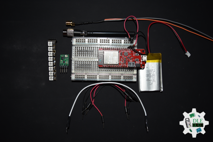
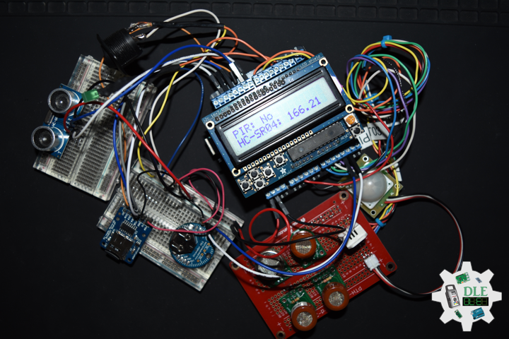
HC-SR04 Ultrasonic Sensor
This is the HC-SR04 ultrasonic distance sensor. This economical sensor provides 2cm to 400cm of non-contact measurement functionality with a ranging accuracy that can reach up to 3mm. Each HC-SR04 module includes an ultrasonic transmitter, a receiver and a control circuit.
There are only four pins that you need to worry about on the HC-SR04: VCC (Power), Trig (Trigger), Echo (Receive), and GND (Ground). You will find this sensor very easy to set up and use for your next range-finding project. This sensor has additional control circuitry that can prevent inconsistent “bouncy” data depending on the application.
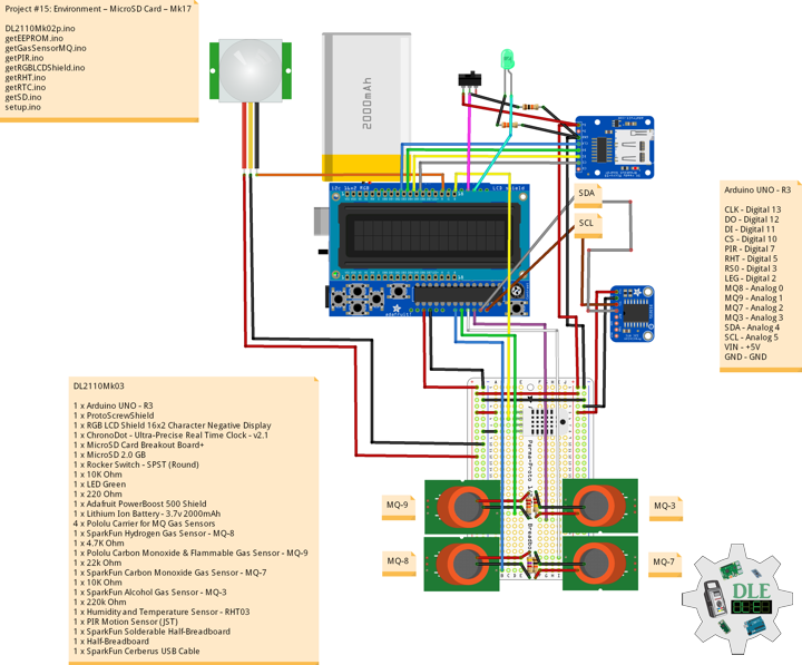
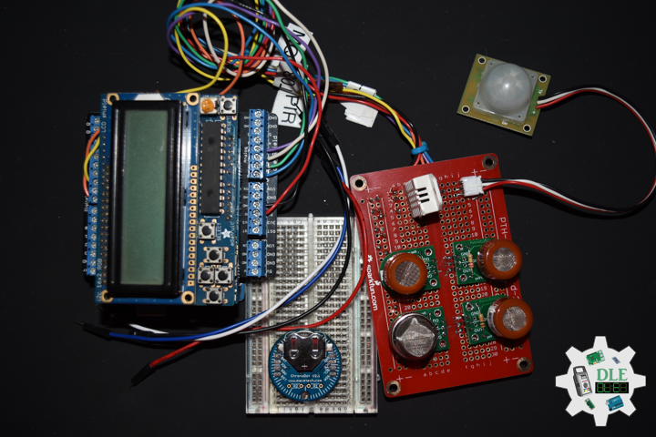
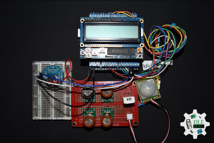
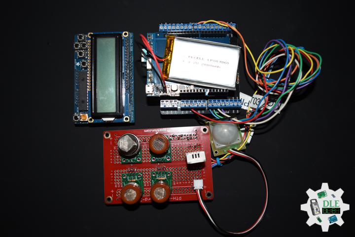
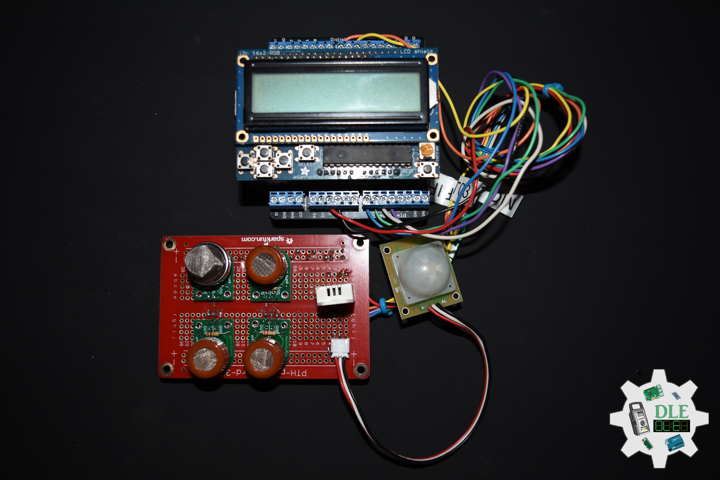
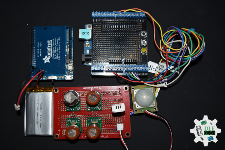
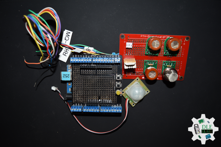
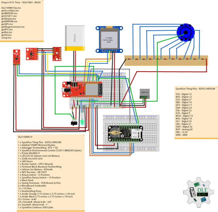
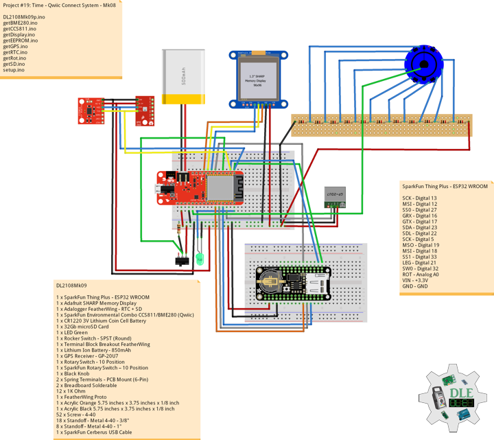
DL2110Mk05
1 x Arduino UNO – R3
1 x ProtoScrewShield
1 x RGB LCD Shield 16×2 Character Negative Display
1 x HC-SR04 Ultrasonic Sensor
1 x ChronoDot – Ultra-Precise Real Time Clock – v2.1
1 x CR1632 Batteries
1 x MicroSD Card Breakout Board+
1 x MicroSD 2.0 GB
1 x Rocker Switch – SPST (Round)
1 x 10K Ohm
1 x LED Green
1 x 220 Ohm
1 x Adafruit PowerBoost 500 Shield
1 x Lithium Ion Battery – 3.7v 2000mAh
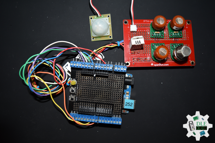
4 x Pololu Carrier for MQ Gas Sensors
1 x SparkFun Hydrogen Gas Sensor – MQ-8
1 x 4.7K Ohm
1 x Pololu Carbon Monoxide & Flammable Gas Sensor – MQ-9
1 x 22k Ohm
1 x SparkFun Carbon Monoxide Gas Sensor – MQ-7
1 x 10K Ohm
1 x SparkFun Alcohol Gas Sensor – MQ-3
1 x 220k Ohm
1 x Temperature and Humidity Sensor- RHT03
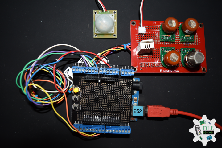
1 x PIR Motion Sensor (JST)
1 x SparkFun Solderable Half-Breadboard
1 x Half-Breadboard
1 x SparkFun Cerberus USB Cable
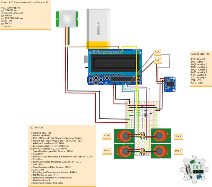
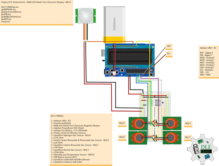
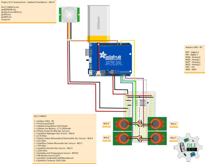
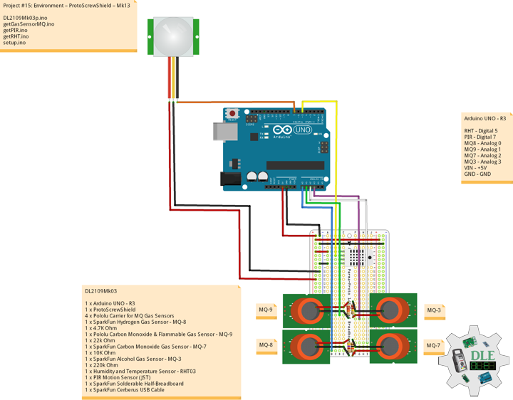
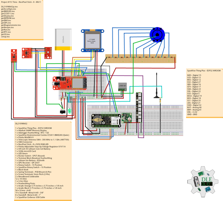
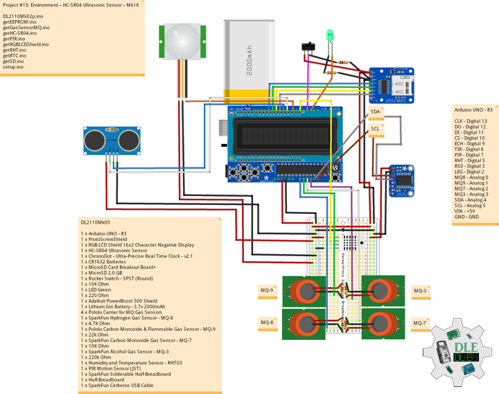
Arduino UNO – R3
CLK – Digital 13
DO – Digital 12
DI – Digital 11
CS – Digital 10
ECH – Digital 9
TIR – Digital 8
PIR – Digital 7
RHT – Digital 5
RS0 – Digital 3
LEG – Digital 2
MQ8 – Analog 0
MQ9 – Analog 1
MQ7 – Analog 2
MQ3 – Analog 3
SDA – Analog 4
SCL – Analog 5
VIN – +5V
GND – GND
DL2110Mk05p.ino
/*
***** Don Luc Electronics © *****
Software Version Information
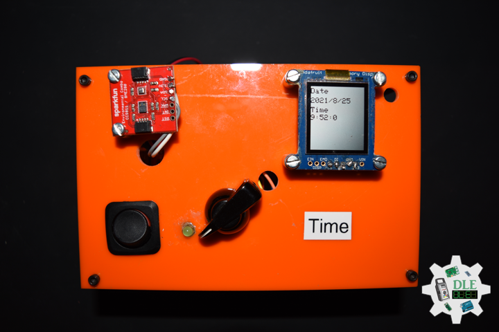
Project #15: Environment – HC-SR04 Ultrasonic Sensor – Mk18
10-05
DL2110Mk05p.ino
1 x Arduino UNO - R3
1 x ProtoScrewShield
1 x RGB LCD Shield 16x2 Character Negative Display
1 x HC-SR04 Ultrasonic Sensor
1 x ChronoDot - Ultra-Precise Real Time Clock - v2.1
1 x CR1632 Batteries
1 x MicroSD Card Breakout Board+
1 x MicroSD 2.0 GB
1 x Rocker Switch - SPST (Round)
1 x 10K Ohm
1 x LED Green
1 x 220 Ohm
1 x Adafruit PowerBoost 500 Shield
1 x Lithium Ion Battery - 3.7v 2000mAh
4 x Pololu Carrier for MQ Gas Sensors
1 x SparkFun Hydrogen Gas Sensor - MQ-8
1 x 4.7K Ohm
1 x Pololu Carbon Monoxide & Flammable Gas Sensor - MQ-9
1 x 22k Ohm
1 x SparkFun Carbon Monoxide Gas Sensor - MQ-7
1 x 10K Ohm
1 x SparkFun Alcohol Gas Sensor - MQ-3
1 x 220k Ohm
1 x Temperature and Humidity Sensor - RHT03
1 x PIR Motion Sensor (JST)
1 x SparkFun Solderable Half-Breadboard
1 x Half-Breadboard
1 x SparkFun Cerberus USB Cable
*/
// Include the Library Code
// EEPROM Library to Read and Write EEPROM with Unique ID for Unit
#include <EEPROM.h>
// RHT Temperature and Humidity Sensor
#include <SparkFun_RHT03.h>
// Adafruit RGB LCD Shield 16x2
#include <Adafruit_RGBLCDShield.h>
// Wire
#include <Wire.h>
// DS3231 RTC Date and Time
#include <RTClib.h>
// SD Card
#include <SPI.h>
#include <SD.h>
// RHT Temperature and Humidity Sensor
// RHT03 data pin Digital 5
const int RHT03_DATA_PIN = 5;
// This creates a RTH03 object, which we'll use to interact with the sensor
RHT03 rht;
float latestHumidity;
float latestTempC;
// Gas Sensors MQ
// Hydrogen Gas Sensor - MQ-8
int iMQ8 = A0;
int iMQ8Raw = 0;
int iMQ8ppm = 0;
// Two points are taken from the curve in datasheet.
// With these two points, a line is formed which is
// "approximately equivalent" to the original curve.
float H2Curve[3] = {2.3, 0.93,-1.44};
// Carbon Monoxide & Flammable Gas Sensor - MQ-9
int iMQ9 = A1;
int iMQ9Raw = 0;
int iMQ9ppm = 0;
// Carbon Monoxide Gas Sensor - MQ-7
int iMQ7 = A2;
int iMQ7Raw = 0;
int iMQ7ppm = 0;
// Alcohol Gas Sensor - MQ-3
int iMQ3 = A3;
int iMQ3Raw = 0;
int iMQ3ppm = 0;
// PIR Motion
// Motion detector
const int iMotion = 7;
// Proximity
int proximity = LOW;
String Det = "";
// Adafruit RGB LCD Shield
Adafruit_RGBLCDShield RGBLCDShield = Adafruit_RGBLCDShield();
// These #defines make it easy to set the backlight color
#define OFF 0x0
#define RED 0x1
#define YELLOW 0x3
#define GREEN 0x2
#define TEAL 0x6
#define BLUE 0x4
#define VIOLET 0x5
#define WHITE 0x7
// Momentary Button
int yy = 0;
uint8_t momentaryButton = 0;
// DS3231 RTC Date and Time
RTC_DS3231 rtc;
String sDate;
String sTime;
// SD Card
const int chipSelect = 10;
String zzzzzz = "";
// LED Green
int iLEDGreen = 2;
// Rocker Switch - SPST (Round)
int iSS1 = 3;
// State
int iSS1State = 0;
// HC-SR04 Ultrasonic Sensor
int iTrig = 8;
int iEcho = 9;
// Stores the distance measured by the distance sensor
float distance = 0;
// Software Version Information
String uid = "";
// Version
String sver = "15-18";
void loop()
{
// Adafruit RGB LCD Shield
// Clear
RGBLCDShield.clear();
// iLEDGreen LOW
digitalWrite(iLEDGreen, LOW );
// RHT Temperature and Humidity Sensor
isRHT03();
// Gas Sensors MQ
isGasSensor();
// isPIR Motion
isPIR();
// DS3231 RTC Date and Time
isRTC();
// HC-SR04 Ultrasonic Sensor
isHCSR04();
// Adafruit RGB LCD Shield
// Display
isDisplay();
// Slide Switch
// Read the state of the iSS1 value
iSS1State = digitalRead(iSS1);
// If it is the Slide Switch State is HIGH
if (iSS1State == HIGH) {
// iLEDGreen HIGH
digitalWrite(iLEDGreen, HIGH );
// MicroSD Card
isSD();
} else {
// iLEDGreen LOW
digitalWrite(iLEDGreen, LOW );
}
// Delay
delay( 500 );
}
getEEPROM.ino
// EEPROM
// isUID EEPROM Unique ID
void isUID()
{

  // Is Unit ID
  uid = "";
  for (int x = 0; x < 5; x++)
  {
    uid = uid + char(EEPROM.read(x));
  }

}
getGasSensorMQ.ino
// Gas Sensors MQ
// Gas Sensor
void isGasSensor() {

  // Read in analog value from each gas sensors

  // Hydrogen Gas Sensor - MQ-8
  iMQ8Raw = analogRead( iMQ8 );

  // Carbon Monoxide & Flammable Gas Sensor - MQ-9
  iMQ9Raw = analogRead( iMQ9 );

  // Carbon Monoxide Gas Sensor - MQ-7
  iMQ7Raw = analogRead( iMQ7 );

  // Alcohol Gas Sensor - MQ-3
  iMQ3Raw = analogRead( iMQ3 );

  // Caclulate the PPM of each gas sensors

  // Hydrogen Gas Sensor - MQ-8
  iMQ8ppm = isMQ8( iMQ8Raw );

  // Carbon Monoxide & Flammable Gas Sensor - MQ-9
  iMQ9ppm = isMQ9( iMQ9Raw );

  // Carbon Monoxide Gas Sensor - MQ-7
  iMQ7ppm = isMQ7( iMQ7Raw );

  // Alcohol Gas Sensor - MQ-3
  iMQ3ppm = isMQ3( iMQ3Raw );

}
// Hydrogen Gas Sensor - MQ-8 - PPM
int isMQ8(double rawValue) {

  // RvRo
  double RvRo = rawValue * (3.3 / 1023);

  return (pow(4.7,( ((log(RvRo)-H2Curve[1])/H2Curve[2]) + H2Curve[0])));

}
// Carbon Monoxide & Flammable Gas Sensor - MQ-9
int isMQ9(double rawValue) {

  double RvRo = rawValue * 3.3 / 4095;

  double ppm = 3.027*exp(1.0698*( RvRo ));
  return ppm;

}
// Carbon Monoxide Gas Sensor - MQ-7
int isMQ7(double rawValue) {

  double RvRo = rawValue * 3.3 / 4095;

  double ppm = 3.027*exp(1.0698*( RvRo ));
  return ppm;

}
// Alcohol Gas Sensor - MQ-3
int isMQ3(double rawValue) {

  double RvRo = rawValue * 3.3 / 4095;

  double bac = RvRo * 0.21;
  return bac;

}
getHC-SR04.ino
// HC-SR04 Ultrasonic Sensor
// Setup HC-SR04
void setupHCSR04() {

  // The trigger iTrig will output pulses of electricity
  pinMode(iTrig, OUTPUT);
  // The echo iEcho will measure the duration of pulses coming back from the distance sensor
  pinMode(iEcho, INPUT);

}
// HC-SR04
void isHCSR04() {

  // Variable to store the distance measured by the sensor
  distance = isDistance();

}
// Distance
float isDistance() {

  // Variable to store the time it takes for a ping to bounce off an object
  float echoTime;
  // Variable to store the distance calculated from the echo time
  float calculatedDistance;

  // Send out an ultrasonic pulse that's 10ms long
  digitalWrite(iTrig, HIGH);
  delayMicroseconds(10);
  digitalWrite(iTrig, LOW);

  // Use the pulseIn command to see how long it takes for the
  // pulse to bounce back to the sensor
  echoTime = pulseIn(iEcho, HIGH);

  // Calculate the distance of the object that reflected the pulse
  // (half the bounce time multiplied by the speed of sound)
  // cm = 58.0
  calculatedDistance = echoTime / 58.0;

  // Send back the distance that was calculated
  return calculatedDistance;

}
getPIR.ino
// PIR Motion
// Setup PIR
void setupPIR() {

  // Setup PIR Montion
  pinMode(iMotion, INPUT_PULLUP);

}
// isPIR Motion
void isPIR() {

  // Proximity
  proximity = digitalRead(iMotion);
  if (proximity == LOW)
  {

    // PIR Motion Sensor's LOW, Motion is detected
    Det = "Motion Yes";

  }
  else
  {

    // PIR Motion Sensor's HIGH
    Det = "No";

  }

}
getRGBLCDShield.ino
// Adafruit RGB LCD Shield
// Setup RGB LCD Shield
void isSetupRGBLCDShield() {
// Adafruit RGB LCD Shield
// Set up the LCD's number of columns and rows:
RGBLCDShield.begin(16, 2);
// Set the cursor to column 0, line 0
RGBLCDShield.setBacklight(RED);
// Don luc
RGBLCDShield.setCursor(0,0);
RGBLCDShield.print("Don Luc");
// Set the cursor to column 0, line 1
RGBLCDShield.setCursor(0, 1);
// Electronics
RGBLCDShield.print("Electronics");
// Delay
delay(5000);
// Clear
RGBLCDShield.clear();
// Set the cursor to column 0, line 0
RGBLCDShield.setBacklight(TEAL);
// Version
RGBLCDShield.setCursor(0,0);
RGBLCDShield.print("Version: " + sver);
// Set the cursor to column 0, line 1
RGBLCDShield.setCursor(0, 1);
// Unit ID
RGBLCDShield.print("Unit ID: " + uid);
// Delay
delay(5000);
// Clear
RGBLCDShield.clear();
}
// isDisplay
void isDisplay() {
// Momentary Button
momentaryButton = RGBLCDShield.readButtons();
switch ( yy ) {
case 1:
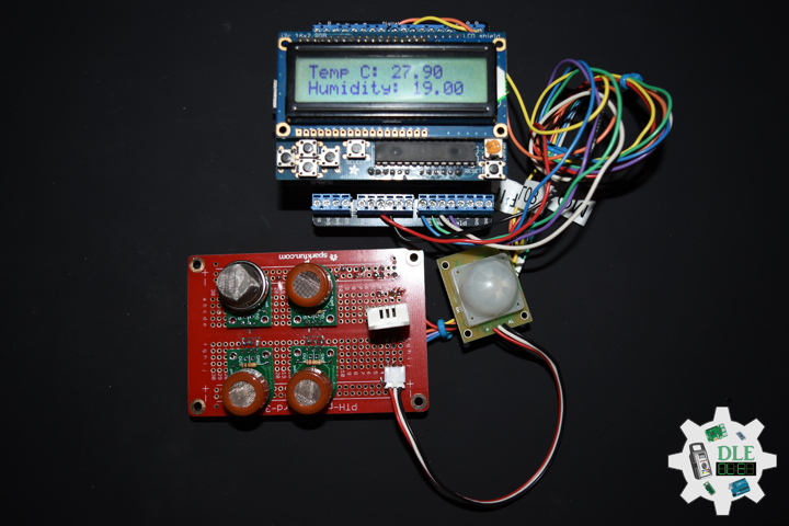
// RHT Temperature and Humidity Sensor
// Set the cursor to column 0, line 0
RGBLCDShield.setCursor(0,0);
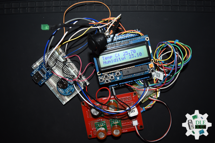
// Temperature C
RGBLCDShield.print( "Temp C: " );
RGBLCDShield.print( latestTempC );
// Set the cursor to column 0, line 1
RGBLCDShield.setCursor(0, 1);
// Humidity
RGBLCDShield.print( "Humidity: " );
RGBLCDShield.print( latestHumidity );
break;
case 2:
// Set the cursor to column 0, line 0
// PIR Motion Sensor
RGBLCDShield.setCursor(0,0);
RGBLCDShield.print( "PIR: " );
RGBLCDShield.print( Det );
// Set the cursor to column 0, line 1
// HC-SR04 Ultrasonic Sensor
RGBLCDShield.setCursor(0, 1);
RGBLCDShield.print( "HC-SR04: " );
RGBLCDShield.print( distance );
break;
case 3:
// Gas Sensors 1
// Set the cursor to column 0, line 0
RGBLCDShield.setCursor(0,0);
// Hydrogen Gas Sensor - MQ-8
RGBLCDShield.print( "MQ-8: " );
RGBLCDShield.print( iMQ8ppm );
// Set the cursor to column 0, line 1
RGBLCDShield.setCursor(0, 1);
// Carbon Monoxide & Flammable Gas Sensor - MQ-9
RGBLCDShield.print( "MQ-9: " );
RGBLCDShield.print( iMQ9ppm );
break;
case 4:
// Gas Sensors 2
// Set the cursor to column 0, line 0
RGBLCDShield.setCursor(0,0);
// Carbon Monoxide Gas Sensor - MQ-7
RGBLCDShield.print( "MQ-7: " );
RGBLCDShield.print( iMQ7ppm );
// Set the cursor to column 0, line 1
RGBLCDShield.setCursor(0, 1);
// Alcohol Gas Sensor - MQ-3
RGBLCDShield.print( "MQ-3: " );
RGBLCDShield.print( iMQ3ppm );
break;
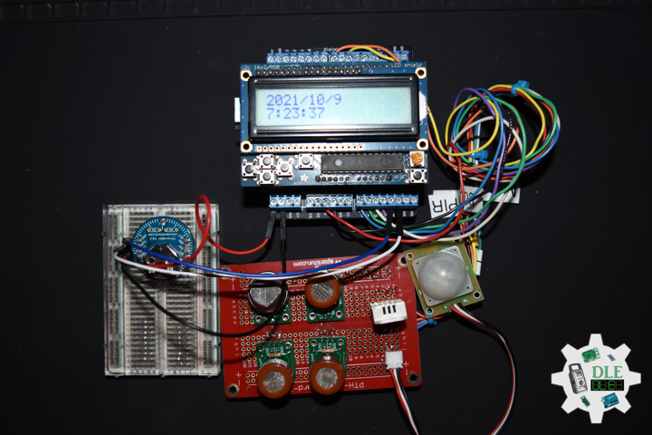
case 5:
// DS3231 RTC Date and Time
// Date and Time
DateTime now = rtc.now();
// Set the cursor to column 0, line 0
// Date
RGBLCDShield.setCursor(0,0);
RGBLCDShield.print( sDate );
// Set the cursor to column 0, line 1
RGBLCDShield.setCursor(0, 1);
// Time
RGBLCDShield.print( sTime );
break;
default:
// Don luc Electronics
yy = 5;
RGBLCDShield.setBacklight(RED);
// Set the cursor to column 0, line 0
// Don luc
RGBLCDShield.setCursor(0,0);
RGBLCDShield.print("Don Luc");
// Set the cursor to column 0, line 1
RGBLCDShield.setCursor(0, 1);
// Electronics
RGBLCDShield.print("Electronics");
}
if ( momentaryButton ) {
if ( momentaryButton & BUTTON_UP ) {
yy = 1;
// RHT Temperature and Humidity Sensor
RGBLCDShield.setBacklight(GREEN);
}
if ( momentaryButton & BUTTON_DOWN ) {
yy = 2;
// PIR Motion Sensor
RGBLCDShield.setBacklight(VIOLET);
}
if ( momentaryButton & BUTTON_LEFT ) {
yy = 3;
// Gas Sensors 1
RGBLCDShield.setBacklight(TEAL);
}
if ( momentaryButton & BUTTON_RIGHT ) {
yy = 4;
// Gas Sensors 2
RGBLCDShield.setBacklight(YELLOW);
}
if ( momentaryButton & BUTTON_SELECT ) {
yy = 5;
// DS3231 RTC Date and Time
RGBLCDShield.setBacklight(WHITE);
}
}
}
getRHT.ino
// RHT Temperature and Humidity Sensor
// setup RHT Temperature and Humidity Sensor
void setupRTH03() {

  // RHT Temperature and Humidity Sensor
  // Call rht.begin() to initialize the sensor and our data pin
  rht.begin(RHT03_DATA_PIN);

}
// RHT Temperature and Humidity Sensor
void isRHT03(){

  // Call rht.update() to get new humidity and temperature values from the sensor.
  int updateRet = rht.update();

  // The humidity(), tempC(), and tempF() functions can be called -- after
  // a successful update() -- to get the last humidity and temperature value
  latestHumidity = rht.humidity();
  latestTempC = rht.tempC();

}
getRTC.ino
// DS3231 RTC Date and Time
// Setup DS3231 RTC
void isSetupRTC() {

  if (! rtc.begin()) {
    while (1);
  }

  if (rtc.lostPower()) {
    // Following line sets the RTC to the date & time this sketch was compiled
    rtc.adjust(DateTime(F(__DATE__), F(__TIME__)));
    // This line sets the RTC with an explicit date & time, for example to set
    // January 21, 2014 at 3am you would call:
    // rtc.adjust(DateTime(2014, 1, 21, 3, 0, 0));
  }

}
// DS3231 RTC Date and Time
void isRTC(){

    // Date and Time
    sDate = "";
    sTime = "";
    // Date Time
    DateTime now = rtc.now();

    // sData
    sDate += String(now.year(), DEC);
    sDate += "/";
    sDate += String(now.month(), DEC);
    sDate += "/";
    sDate += String(now.day(), DEC);

    // sTime
    sTime += String(now.hour(), DEC);
    sTime += ":";
    sTime += String(now.minute(), DEC);
    sTime += ":";
    sTime += String(now.second(), DEC);

}
getSD.ino
// MicroSD Card
// MicroSD Setup
void setupSD() {

  // MicroSD Card
  if (!SD.begin(chipSelect)) {

     while (true);

  }

}
// MicroSD Card
void isSD() {

  zzzzzz = "";

  // Don Luc Electronics © (1983-2021)
  // Arduino Data
  // EEPROM Unique ID
  // Version
  // Date
  // Time
  // Temperature Celsius
  // Humidity
  // Hydrogen Gas Sensor - MQ-8
  // Carbon Monoxide & Flammable Gas Sensor - MQ-9
  // Carbon Monoxide Gas Sensor - MQ-7
  // Alcohol Gas Sensor - MQ-3
  // PIR Motion
  // HC-SR04 Ultrasonic Sensor
  // EEPROM Unique ID|Version|Date|Time|Temperature Celsius|Humidity|MQ-8|MQ-9|MQ-7|MQ-3|PIR Motion|HC-SR04|
  zzzzzz = uid + "|" + sver + "|" + sDate + "|" + sTime + "|" + latestTempC + "|" + latestHumidity + "|"
  + iMQ8ppm + "|" + iMQ9ppm + "|" + iMQ7ppm + "|" +
  iMQ3ppm + "|" + Det + "|" + distance + "|";


  // Open the file. Note that only one file can be open at a time,
  // so you have to close this one before opening another.

  File dataFile = SD.open("arddata.txt", FILE_WRITE);

  // If the file is available, write to it:
  if ( dataFile ) {

    dataFile.println( zzzzzz );

    dataFile.close();

  }

}
setup.ino
// Setup
void setup()
{

  // EEPROM Unique ID
  isUID();

  // RHT Temperature and Humidity Sensor
  // Setup RTH03 Temperature and Humidity Sensor
  setupRTH03();

  // PIR Motion
  // Setup PIR
  setupPIR();

  // Setup DS3231 RTC
  isSetupRTC();

  //MicroSD Card
  setupSD();

  // Initialize the LED Green
  pinMode(iLEDGreen, OUTPUT);
  // iLEDGreen LOW
  digitalWrite(iLEDGreen,  LOW );

  // Slide Switch
  pinMode(iSS1, INPUT);

  // Setup HC-SR04
  setupHCSR04();

  // Adafruit RGB LCD Shield
  isSetupRGBLCDShield();

}
——
People can contact us: https://www.donluc.com/?page_id=1927
Technology Experience
- Single-Board Microcontrollers (PIC, Arduino, Raspberry Pi,Espressif, etc…)
- IoT
- Robotics
- Camera and Video Capture Receiver Stationary, Wheel/Tank and Underwater Vehicle
- Unmanned Vehicles Terrestrial and Marine
- Research & Development (R & D)
- Desktop Applications (Windows, OSX, Linux, Multi-OS, Multi-Tier, etc…)
- Mobile Applications (Android, iOS, Blackberry, Windows Mobile, Windows CE, etc…)
- Web Applications (LAMP, Scripting, Java, ASP, ASP.NET, RoR, Wakanda, etc…)
- Social Media Programming & Integration (Facebook, Twitter, YouTube, Pinterest, etc…)
- Content Management Systems (WordPress, Drupal, Joomla, Moodle, etc…)
- Bulletin Boards (phpBB, SMF, Vanilla, jobberBase, etc…)
- eCommerce (WooCommerce, OSCommerce, ZenCart, PayPal Shopping Cart, etc…)
Instructor and E-Mentor
- IoT
- PIC Microcontrollers
- Arduino
- Raspberry Pi
- Espressif
- Robotics
- DOS, Windows, OSX, Linux, iOS, Android, Multi-OS
- Linux-Apache-PHP-MySQL
Follow Us
J. Luc Paquin – Curriculum Vitae – 2021 English & Español
https://www.jlpconsultants.com/luc/
Web: https://www.donluc.com/
Web: https://www.jlpconsultants.com/
Facebook: https://www.facebook.com/neosteam.labs.9/
YouTube: https://www.youtube.com/channel/UC5eRjrGn1CqkkGfZy0jxEdA
Twitter: https://twitter.com/labs_steam
Pinterest: https://www.pinterest.com/NeoSteamLabs/
Instagram: https://www.instagram.com/neosteamlabs/
Don Luc