——
#DonLucElectronics #DonLuc #TCRT5000 #Robotics #FireBeetle2ESP32E #ESP32 #Display #IoT #Project #Fritzing #Programming #Electronics #Microcontrollers #Consultant
——
——
——
——
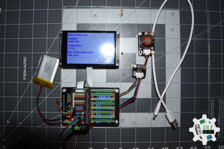
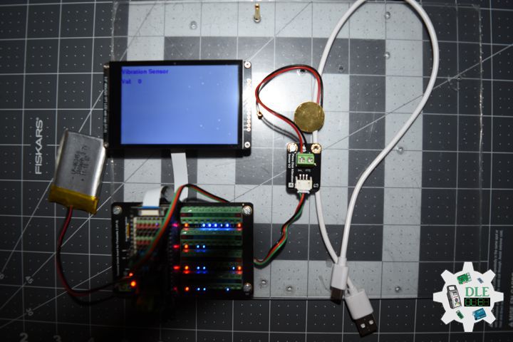
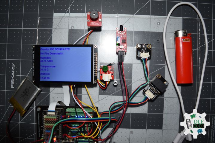
TCRT5000 Optical Infrared Line Follower
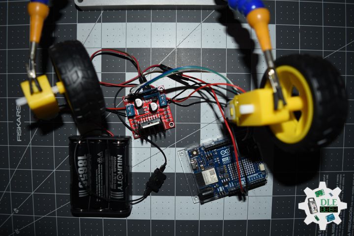
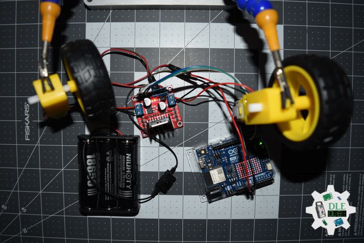
The TCRT5000 is an infrared optical sensor widely used as a line follower in mobile robots and proximity detection systems. It consists of an infrared emitter (IR LED) and a phototransistor receiver, housed in a single package. Its operation is based on the principle of reflection: the LED emits infrared light toward a surface, and the phototransistor detects the amount of light reflected. Light surfaces (such as white lines) reflect more light, while dark surfaces (such as black lines) absorb it, allowing the sensor to differentiate between the two. This capability makes it an essential tool for line-following robots, as it enables them to detect and follow paths marked on the ground.
The TCRT5000 infrared optical sensor, commonly used as a line follower, has diverse applications in electronics and robotics projects. Its main uses include line-following robots, edge detection, speed or rotation measurement with encoders, and object or people counting.
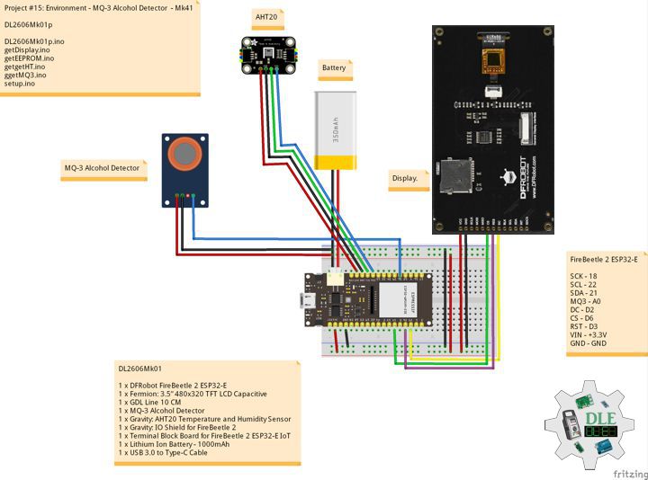
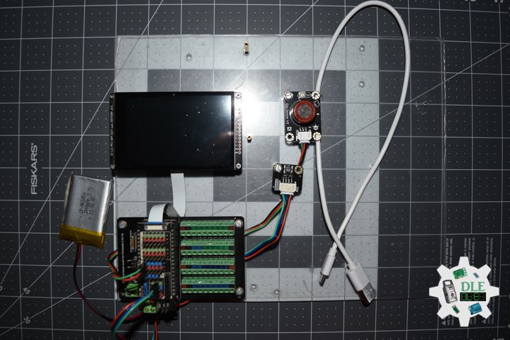
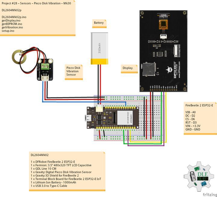
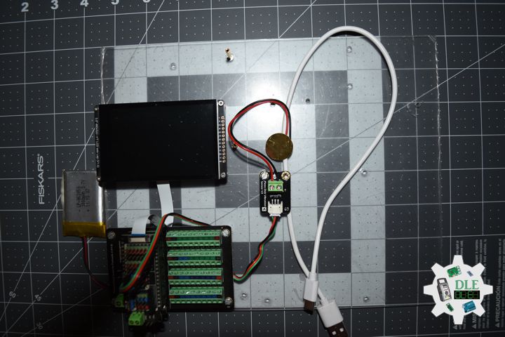
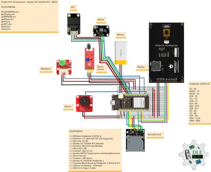
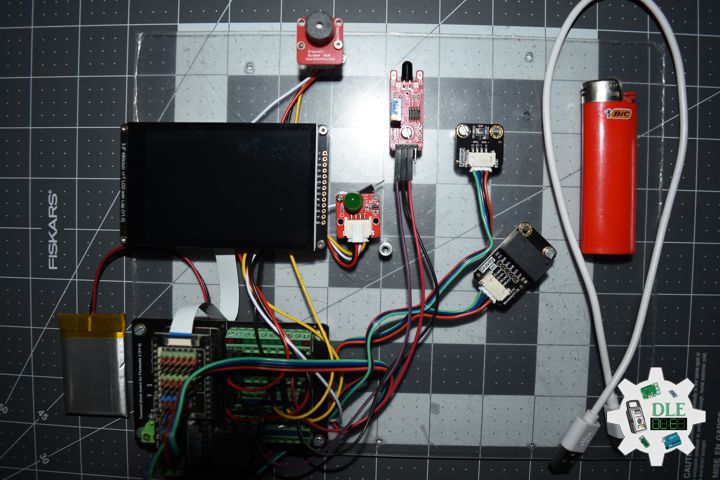
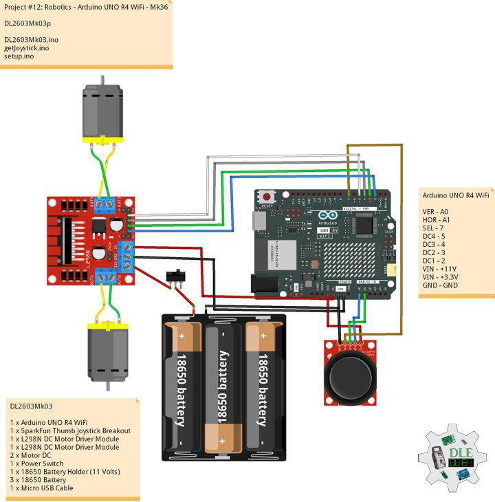
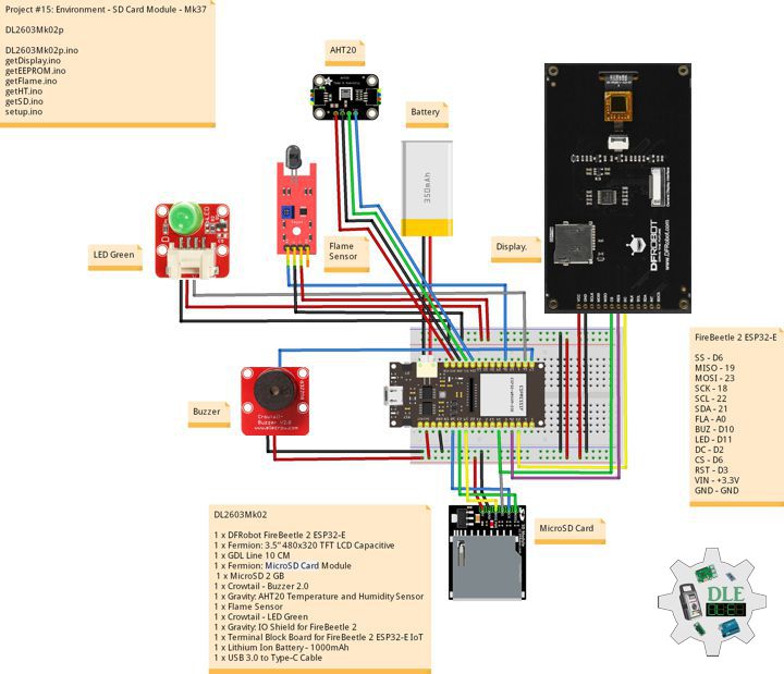
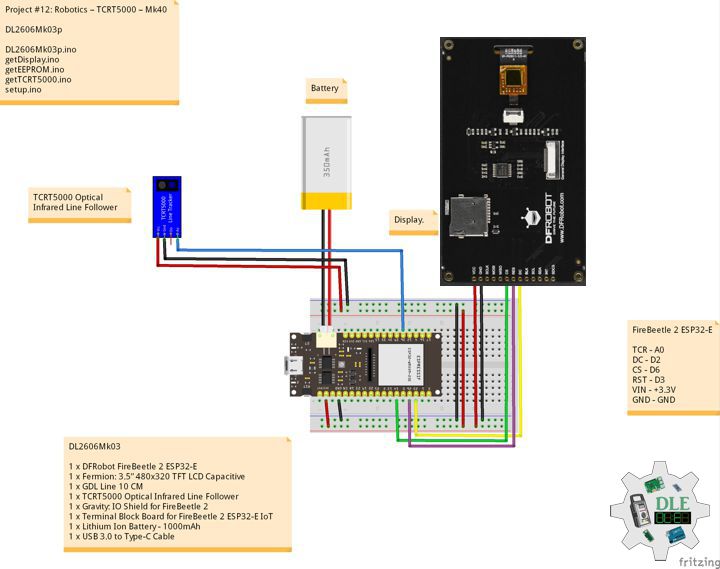
DL2606Mk03
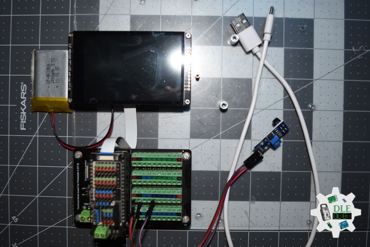
1 x DFRobot FireBeetle 2 ESP32-E
1 x Fermion: 3.5” 480×320 TFT LCD Capacitive
1 x GDL Line 10 CM
1 x TCRT5000 Optical Infrared Line Follower
1 x Gravity: IO Shield for FireBeetle 2
1 x Terminal Block Board for FireBeetle 2 ESP32-E IoT
1 x Lithium Ion Battery – 1000mAh
1 x USB 3.0 to Type-C Cable
DL2606Mk03p
DL2606Mk03p.ino
/****** Don Luc Electronics © ******
Software Version Information
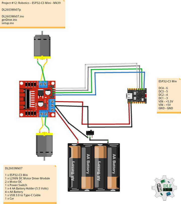
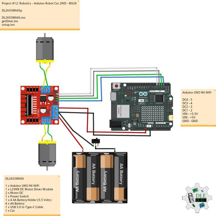
Project #12: Robotics – TCRT5000 – Mk40
12-40
DL2606Mk03p.ino
DL2606k03
1 x DFRobot FireBeetle 2 ESP32-E
1 x Fermion: 3.5” 480x320 TFT LCD Capacitive
1 x GDL Line 10 CM
1 x TCRT5000 Optical Infrared Line Follower
1 x Gravity: IO Shield for FireBeetle 2
1 x Terminal Block Board for FireBeetle 2 ESP32-E IoT
1 x Lithium Ion Battery - 1000mAh
1 x USB 3.0 to Type-C Cable
*/
// Include the Library Code
// EEPROM Library to Read and Write EEPROM with Unique ID for Unit
#include "EEPROM.h"
// DFRobot Display GDL API
#include <DFRobot_GDL.h>
// TCRT5000 Optical Infrared Line
int iTCRT5000 = A0;
// Value
int iValue = 0;
// Voltage
float fVoltage;
// Print
String sPrint = "";
// Defined ESP32
#define TFT_DC D2
#define TFT_CS D6
#define TFT_RST D3
/*dc=*/ /*cs=*/ /*rst=*/
// DFRobot Display 320x480
DFRobot_ILI9488_320x480_HW_SPI screen(TFT_DC, TFT_CS, TFT_RST);
// Software Version Information
// EEPROM Unique ID Information
#define EEPROM_SIZE 64
String uid = "";
// Software Version Information
String sver = "12-40";
void loop() {
// isTCRT5000
isTCRT5000();
// isDisplay TCRT5000
isDisplayTCRT5000();
// Delay 1 Second
delay( 1000 );
}
getDisplay.ino
// DFRobot Display 320x480
// DFRobot Display 320x480 - UID
void isDisplayUID(){
// DFRobot Display 320x480
// Text Display
// Text Wrap
screen.setTextWrap(false);
// Rotation
screen.setRotation(3);
// Fill Screen => black
screen.fillScreen(0x0000);
// Text Color => white
screen.setTextColor(0xffff);
// Font => Free Sans Bold 12pt
screen.setFont(&FreeSansBold12pt7b);
// TextSize => 1.5
screen.setTextSize(1.5);
// Don Luc Electronics
screen.setCursor(0, 30);
screen.println("Don Luc Electronics");
// Tilt Switch
screen.setCursor(0, 60);
screen.println("TCRT5000 Optical Infrared Line Follower");
// Version
screen.setCursor(0, 90);
screen.println("Version");
screen.setCursor(0, 120);
screen.println( sver );
// EEPROM
screen.setCursor(0, 150);
screen.println("EEPROM");
screen.setCursor(0, 180);
screen.println( uid );
}
// isDisplay TCRT5000
void isDisplayTCRT5000(){
// DFRobot Display 320x480
// Text Display
// Text Wrap
screen.setTextWrap(false);
// Rotation
screen.setRotation(3);
// Fill Screen => white
screen.fillScreen(0xffff);
// Text Color => blue
screen.setTextColor(0x001F);
// Font => Free Sans Bold 12pt
screen.setFont(&FreeSansBold12pt7b);
// TextSize => 1.5
screen.setTextSize(1.5);
// Vibration Senso
screen.setCursor(0, 30);
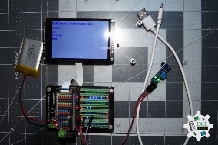
screen.println("TCRT5000 Optical Infrared Line");
// Value
screen.setCursor(0, 70);
screen.println( "Value" );
screen.setCursor(0, 100);
screen.println( iValue );
// Voltage
screen.setCursor(0, 130);
screen.println( "Voltage" );
screen.setCursor(0, 160);
screen.println( fVoltage );
// Print
screen.setCursor(0, 190);
screen.println( "Print" );
screen.setCursor(0, 220);
screen.println( sPrint );
}
getEEPROM.ino
// isUID EEPROM Unique ID
void isUID()
{

  // Is Unit ID
  uid = "";
  for (int x = 0; x < 7; x++)
  {
    uid = uid + char(EEPROM.read(x));
  }

}
getTCRT5000.ino
// TCRT5000 Optical Infrared Line
// isTCRT5000
void isTCRT5000(){

  // isTCRT5000
  iValue = analogRead( iTCRT5000 );

  // Convert the analog reading (which goes from 0 - 4095)
  // to a voltage (0 - 3.3V):
  fVoltage = iValue * (3.3 / 4095.0);

  // the lower the voltage, the brighter it is
  if ((fVoltage >= 0) && (fVoltage <= 0.4)) {

    sPrint = "It is light";

  } else if ((fVoltage > 0.4) && (fVoltage <= 2)) {

    sPrint = "Ot is bright";

  } else {

    sPrint = "It is dark";

  }

}
setup.ino
// Setup
void setup()
{

  // Delay
  delay( 100 );

   // EEPROM Size
  EEPROM.begin(EEPROM_SIZE);

  // EEPROM Unique ID
  isUID();

  // Delay
  delay(100);

  // DFRobot Display 320x480
  screen.begin();

  // Delay
  delay( 100 );

  // DFRobot Display 320x480 - UID
  // Don Luc Electronics
  // Version
  // EEPROM
  isDisplayUID();

  // Wait for the sensor to heat up for 20 seconds
  delay( 5000 );

}
——
Consultant, R&D, Electronics, IoT, Teacher and Instructor
- Programming Language
- Single-Board Microcontrollers (PIC, Arduino, Raspberry Pi, Arm, Silicon Labs, Espressif, Etc…)
- IoT
- Wireless (Radio Frequency, Bluetooth, WiFi, Etc…)
- Robotics
- Automation
- Camera and Video Capture Receiver Stationary, Wheel/Tank , Underwater and UAV Vehicle
- Unmanned Vehicles Terrestrial, Marine and UAV
- Machine Learning
- Artificial Intelligence (AI)
- RTOS
- Sensors, eHealth Sensors, Biosensor, and Biometric
- Research & Development (R & D)
- Consulting
Follow Us
Luc Paquin – Curriculum Vitae – 2026
https://www.donluc.com/luc/LucPaquinCVEng2026Mk01.pdf
https://www.donluc.com/luc/
Web: https://www.donluc.com/
Web: https://www.jlpconsultants.com/
Facebook: https://www.facebook.com/neosteam.labs.9/
YouTube: https://www.youtube.com/@thesass2063
DFRobot: https://learn.dfrobot.com/user-10186.html
TikTok: https://www.tiktok.com/@luc.paquin8
Hackster: https://www.hackster.io/luc-paquin
LinkedIn: https://www.linkedin.com/in/jlucpaquin/
Don Luc