——
#DonLucElectronics #DonLuc #Arduino #EEPROM #DHT11 #ASM #Display #Elecrow #Project #Patreon #Electronics #Microcontrollers #IoT #Fritzing #Programming #Consultant
——
——

——

——
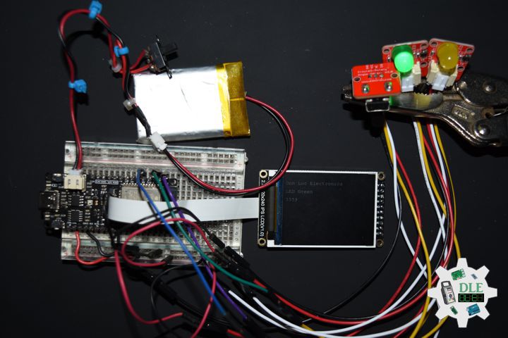
EEPROM
EEPROM (Electrically Erasable Programmable Read-only Memory) is a type of non-volatile memory. EEPROM is a type of non-volatile ROM that enables individual bytes of data to be erased and reprogrammed. That is why EEPROM chips are known as byte erasable chips. EEPROM is usually used to store small amounts of data in computing and other electronic devices. It is used in computers, usually integrated in microcontrollers such as smart cards and remote keyless systems, or as a separate chip device, to store relatively small amounts of data by allowing individual bytes to be erased and reprogrammed.
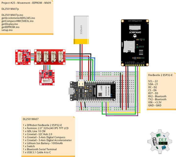
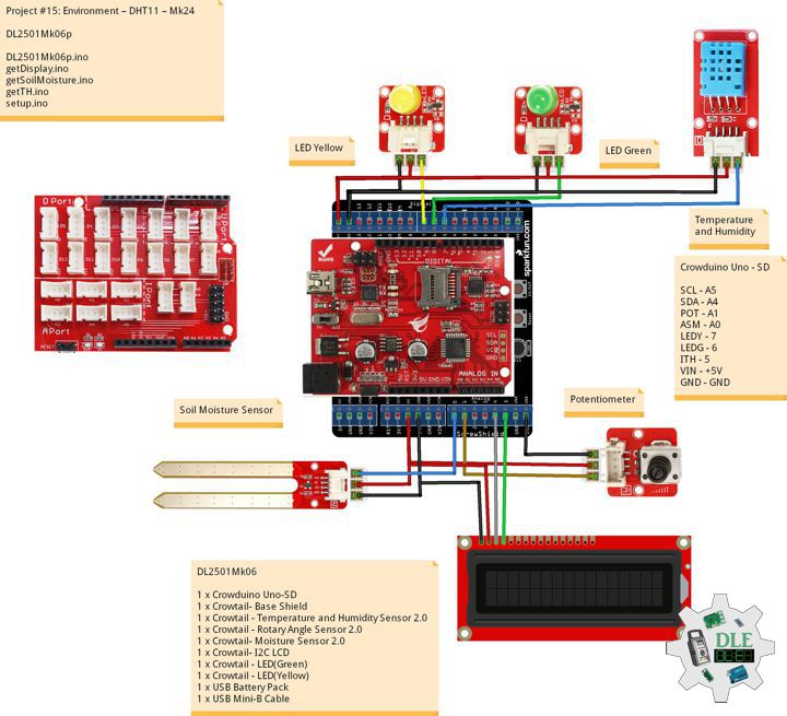
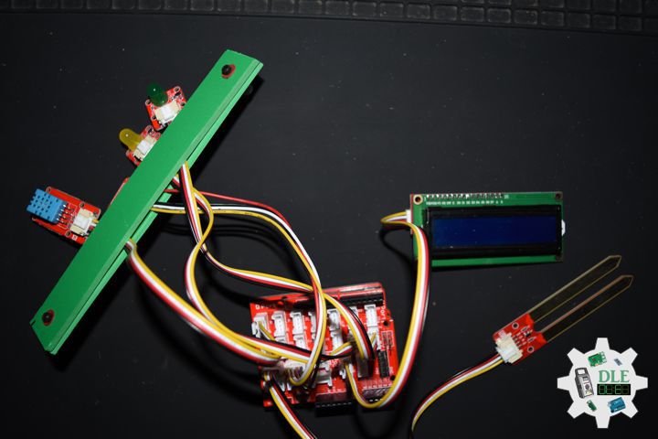
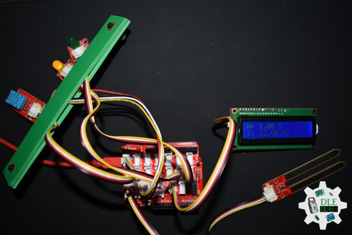
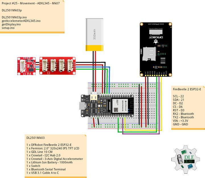
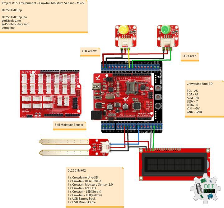
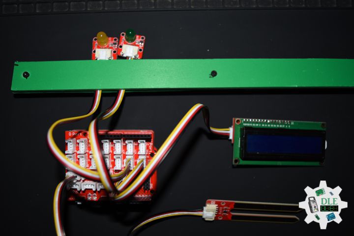
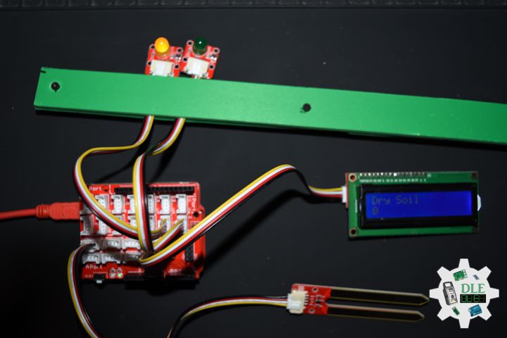
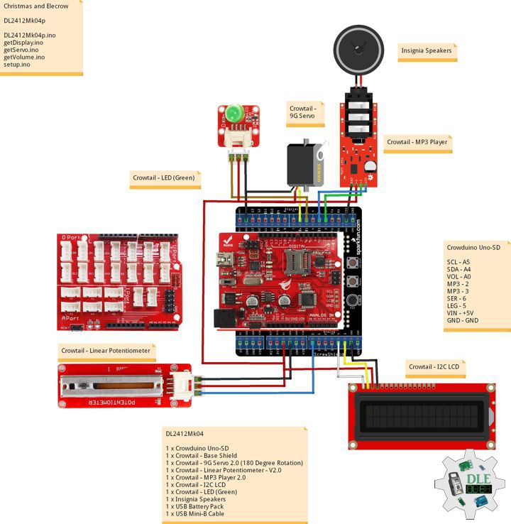
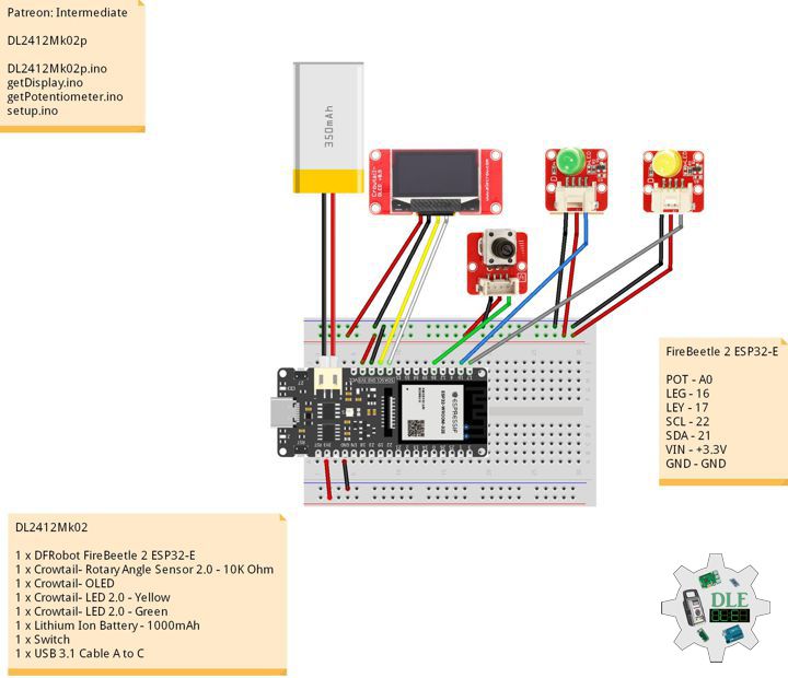
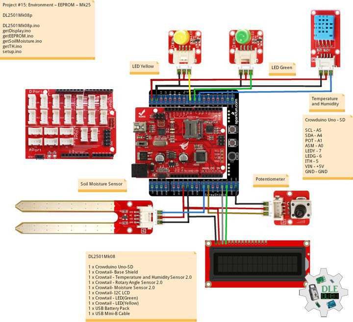
DL2501Mk08
1 x Crowduino Uno – SD
1 x Crowtail – Base Shield
1 x Crowtail – Temperature and Humidity Sensor 2.0
1 x Crowtail – Rotary Angle Sensor 2.0
1 x Crowtail – Moisture Sensor 2.0
1 x Crowtail – I2C LCD
1 x Crowtail – LED(Green)
1 x Crowtail – LED(Yellow)
1 x USB Battery Pack
1 x USB Mini-B Cable
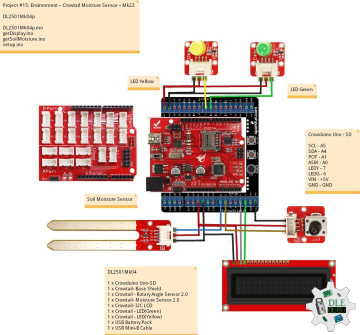
Crowduino Uno – SD
SCL – A5
SDA – A4
POT – A1
ASM – A0
LEDY – 7
LEDG – 6
ITH – 5
VIN – +5V
GND – GND
DLE-EEPROM-UID-UnoMk001
DLE-EEPROM-UID-UnoMk001.ino
/* ***** Don Luc Electronics © ******
Software Version Information
DLE-EEPROM-UID-UnoMk001
Arduino UNO
5V
ver: UnoMk001
EEPROM with unique ID
*/

// Include Library Code
// EEPROM library to read and write EEPROM with unique ID for unit
#include <EEPROM.h>

// Software Version Information
String sver = "UnoMk001";
// Unit ID information
String uid = "DLEU001";
// Read Unique ID
// String ruid = "";

void loop()
{

   // <== Write and Read EEPROM
   isEEPROMw();

}
getEEPROM.ino
// getEEPROM
// Write and Read EEPROM with Unique ID for Unit
void isEEPROMw() {

  // Write EEPROM with Unique ID for Unit
  int incb = 0;
  int v = 0;
  String emp = "";
  String ruid = "";

  // Set Unit ID
  // The message starts with uid then is followed by 7 characters
  // First clear a string buffer
  emp = "";
  // Loop through the 7 ID characters and write their ASCII (byte) value to the EEPROM
  for (int y = 0; y < 7; y++)
  {

     // Get ASCII value of character
     v = int(uid.charAt(y)); // + 5));
     // Add the actual character to the buffer
     emp = emp + uid.charAt(y + 5);
     // Write the value to the EEPROM
     EEPROM.write(y, v);

  }

  // Write EEPROM with Unique ID for Unit
  Serial.println( "Write ID Information");

  // Read ID Information
  // Unit ID
  for (int y = 0; y < 7; y++)
  {

    ruid = ruid + char(EEPROM.read(y));

  }

  // Read ID Information
  Serial.print( "Read ID Information: ");
  Serial.println( ruid );
  Serial.println( "Ok!" );
  ruid = "";

  delay( 5000 );

}
setup.ino
// Setup
void setup()
{

  // Open the serial port at 9600 bps:
  Serial.begin(9600);

  // Serial
  Serial.print( "Software Version Information: ");
  Serial.println( sver );
  Serial.print( "Unit ID Information: ");
  Serial.println( uid );

  delay(5000);

}
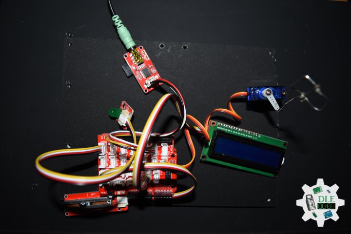
DL2501Mk08p
DL2501Mk08p.ino
/****** Don Luc Electronics © ******
Software Version Information
Project #15: Environment – EEPROM – Mk25
DL2501Mk08p.ino
DL2501Mk08
1 x Crowduino Uno - SD
1 x Crowtail - Base Shield
1 x Crowtail - Temperature and Humidity Sensor 2.0
1 x Crowtail - Rotary Angle Sensor 2.0
1 x Crowtail - Moisture Sensor 2.0
1 x Crowtail - I2C LCD
1 x Crowtail - LED(Green)
1 x Crowtail - LED(Yellow)
1 x USB Battery Pack
1 x USB Mini-B Cable
*/

// Include the Library Code
// EEPROM library to read and write EEPROM with unique ID for unit
#include <EEPROM.h>
// Wire
#include <Wire.h>
// Liquid Crystal
#include "LiquidCrystal.h"
// Temperature and Humidity Sensor
#include "DHT.h"

// Temperature and Humidity Sensor
#define DHTPIN 5
// DHT 11
#define DHTTYPE DHT11
DHT dht(DHTPIN, DHTTYPE);
// Temperature and Humidity Sensor
float h = 0;
float t = 0;

// Potentiometer
int iPotentiometer = A1;
// Change Your Threshold Here
int Threshold = 0;
int zz = 0;

// Liquid Crystal
// Connect via i2c
LiquidCrystal lcd(0);

// Crowtail Moisture Sensor
int iSoilMoisture = A0;
int iSoilMoistureVal = 0;

// LED Yellow
int iLEDYellow = 7;

// LED Green
int iLEDGreen = 6;

// EEPROM Unique ID Information
String uid = "";

// Software Version Information
String sver = "15-25";

void loop() {

  // Crowtail Moisture Sensor
  isSoilMoisture();

  // Temperature and Humidity Sensor
  isTH();

  // Delay 2 Second
  delay( 2000 );

  // Display Temperature and Humidity
  isDisplayTH();

  // Delay 2 Second
  delay( 2000 );

  // Display EEPROM
  isDisplayEEPROM();

  // Delay 2 Second
  delay( 2000 );

}
getDisplay.ino
// getDisplay
// Crowbits - OLED 128X64 UID
void isDisplayUID(){

  // Set up the LCD's number of rows and columns:
  lcd.begin(16, 2);
  // Print a message to the LCD.
  // Cursor
  lcd.setCursor(0, 0);
  lcd.print("Don Luc Electron");
  // Cursor
  lcd.setCursor(0, 1);
  // Print a message to the LCD.
  lcd.print( sver );

}
// isDisplay Green
void isDisplayG(){

  // Print a message to the LCD
  // Clear
  lcd.clear();
  // Cursor
  lcd.setCursor(0, 0);
  lcd.print("Humid Soil");
  // Cursor
  lcd.setCursor(0, 1);
  // Print a message to the LCD
  lcd.print( iSoilMoistureVal );

}
// isDisplay Yellow
void isDisplayY(){

  // Print a message to the LCD
  // Clear
  lcd.clear();
  // Cursor
  lcd.setCursor(0, 0);
  lcd.print("Dry Soil");
  // Cursor
  lcd.setCursor(0, 1);
  // Print a message to the LCD
  lcd.print( iSoilMoistureVal );

}
// Display Temperature and Humidity
void isDisplayTH(){

  // Clear
  lcd.clear();
  // Set the cursor to column 0, line 0
  lcd.setCursor(0, 0);
  lcd.print("H: ");
  lcd.print(h);
  lcd.print(" %");
  // Set the cursor to column 0, line 1
  lcd.setCursor(0, 1);
  lcd.print("T: ");
  lcd.print(t);
  lcd.print(" *C");

}
// Display EEPROM
void isDisplayEEPROM(){

  // Clear
  lcd.clear();
  // Set the cursor to column 0, line 0
  lcd.setCursor(0, 0);
  lcd.print("EEPROM");
  // Set the cursor to column 0, line 1
  lcd.setCursor(0, 1);
  lcd.print( uid );

}
getEEPROM.ino
// EEPROM
// isUID EEPROM Unique ID
void isUID() {

  // Is Unit ID
  uid = "";
  for (int x = 0; x < 7; x++)
  {
    uid = uid + char(EEPROM.read(x));
  }

}
getSoilMoisture.ino
// Crowtail Moisture Sensor
// Soil Moisture
void isSoilMoisture(){

  // Connect Soil Moisture Sensor to Analog 0
  // iSoilMoistureVal => 0~700 Soil Moisture
  iSoilMoistureVal = analogRead( iSoilMoisture );

  // Threshold => 200~500
  zz = analogRead( iPotentiometer );
  Threshold = map( zz, 0, 1024, 200, 500);

  // Threshold
  if (iSoilMoistureVal > Threshold) {

    // 300~700 - Humid Soil
    // LED Yellow
    digitalWrite(iLEDYellow, LOW);
    // Display Green
    isDisplayG();
    // LED Green
    digitalWrite(iLEDGreen, HIGH);

  }
  else {

    // 0-300 Dry Soil
    // LED Green
    digitalWrite(iLEDGreen, LOW);
    // Display Yellow
    isDisplayY();
    digitalWrite(iLEDYellow, HIGH);

  }

}
getTH.ino
// Temperature and Humidity Sensor
void isTH(){

  // Temperature
  t = dht.readTemperature();
  // Humidity
  h = dht.readHumidity();

}
setup.ino
// Setup
void setup()
{

  // Delay
  delay(100);

  // isUID EEPROM Unique ID
  isUID();

  // Delay
  delay(100);

  // Initialize the LED iLED Yellow
  pinMode(iLEDYellow, OUTPUT);

  // Initialize the LED LED Green
  pinMode(iLEDGreen, OUTPUT);

  // Temperature and Humidity Sensor
  dht.begin();

  // Display UID
  isDisplayUID();

  // Delay 5 Second
  delay( 5000 );

}
——
Electronics, IoT, Teacher, Instructor, R&D and Consulting
- Programming Language
- Single-Board Microcontrollers (PIC, Arduino, Raspberry Pi, Arm, Silicon Labs, Espressif, Etc…)
- IoT
- Wireless (Radio Frequency, Bluetooth, WiFi, Etc…)
- Robotics
- Automation
- Camera and Video Capture Receiver Stationary, Wheel/Tank and Underwater Vehicle
- Unmanned Vehicles Terrestrial and Marine
- Machine Learning
- Artificial Intelligence (AI)
- RTOS
- Sensors, eHealth Sensors, Biosensor, and Biometric
- Research & Development (R & D)
- Consulting
Follow Us
Luc Paquin – Curriculum Vitae – 2024
https://www.donluc.com/luc/
Web: https://www.donluc.com/
Facebook: https://www.facebook.com/neosteam.labs.9/
YouTube: https://www.youtube.com/@thesass2063
Twitter: https://twitter.com/labs_steam
Pinterest: https://www.pinterest.com/NeoSteamLabs/
Instagram: https://www.instagram.com/neosteamlabs/
Patreon: https://patreon.com/DonLucElectronics59
DFRobot: https://learn.dfrobot.com/user-10186.html
Hackster.io: https://www.hackster.io/neosteam-labs
Elecrow: https://www.elecrow.com/share/sharepj/center/no/760816d385ebb1edc0732fd873bfbf13
TikTok: https://www.tiktok.com/@luc.paquin8
Twitch: https://www.twitch.tv/lucpaquin
LinkedIn: https://www.linkedin.com/in/jlucpaquin/
Don Luc