——
#DonLucElectronics #DonLuc #Time #RTC #Display #Adalogger #MicroSD #GPSReceiver #Arduino #ESP32 #SparkFunESP32WROOM #Project #Programming #Electronics #Microcontrollers #Consultant #VideoBlog
——
——
——
——
——
Adalogger FeatherWing – RTC + SD
A Feather board without ambition is a Feather board without FeatherWings. This is the Adalogger FeatherWing: it adds both a battery-backed Real Time Clock and MicroSD card storage to any Feather main board. This FeatherWing will make it real easy to add datalogging to any of our existing Feathers. You get both an I2C Real Time Clock (PCF8523) with 32KHz crystal and battery backup, and a MicroSD socket that connects to the SPI port pins.
MicroSD Card
If you have a project with any audio, video, graphics, data logging, etc in it, you’ll find that having a removable storage option is essential. Most microcontrollers have extremely limited built-in storage. If you’re doing any sort of data logging, graphics or audio, you’ll need at least a megabyte of storage, and 64M is probably the minimum.
MicroSD cards are ‘raw’ storage. They’re just sectors in a flash chip, there’s no structure that you have to use. That means you could format an SD card to be a Linux filesystem, a FAT (DOS) filesystem or a Mac filesystem. You could also not have any filesystem at all. However, 99% of computers, cameras, MP3 players, GPS loggers, etc require FAT16 or FAT32 for the filesystem. The tradeoff here is that for smaller microcontrollers the addition of the complex file format handling can take a lot of flash storage and RAM.
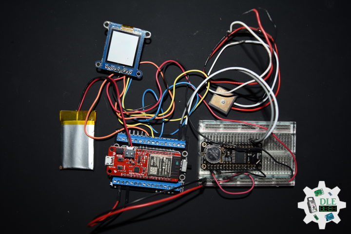
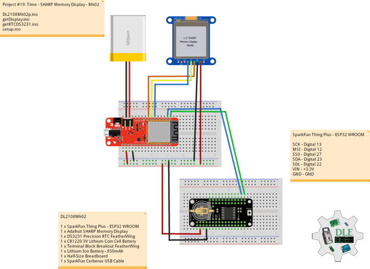
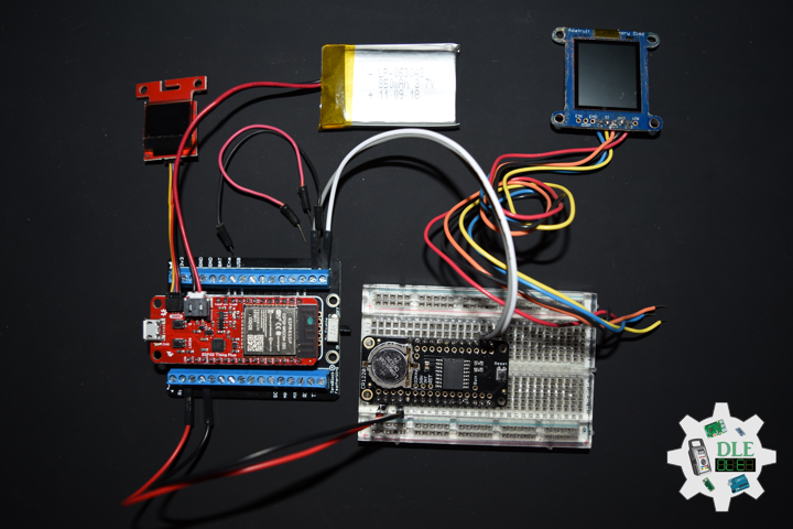
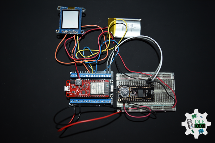
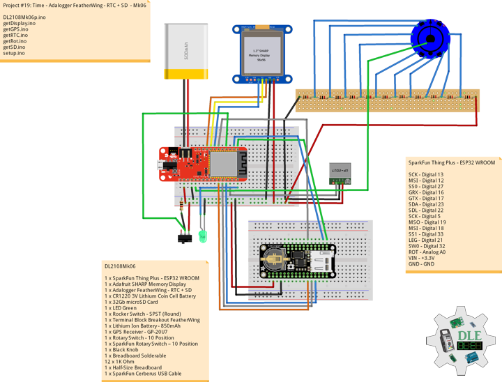
DL2108Mk06
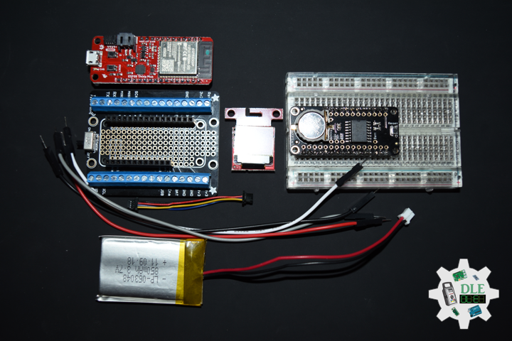
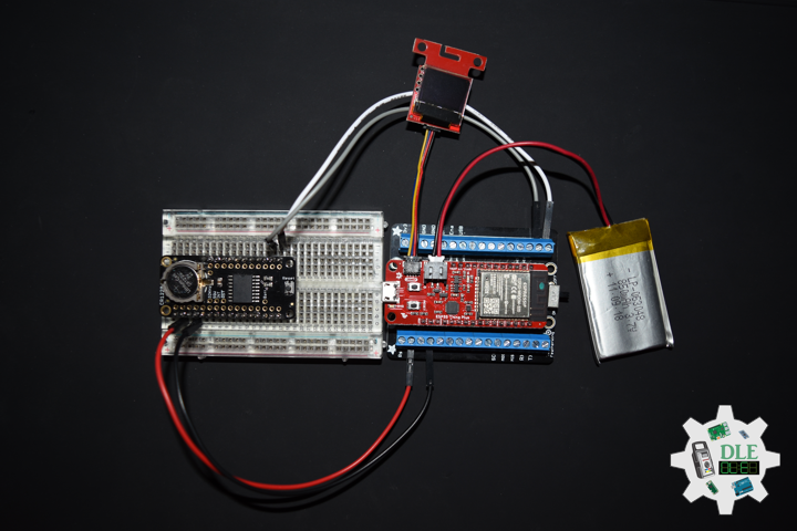
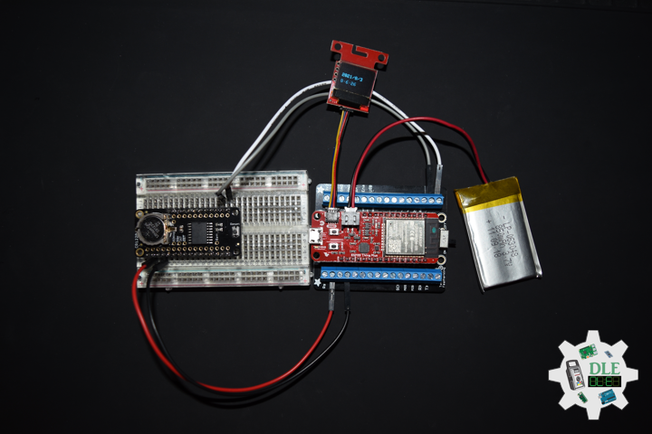
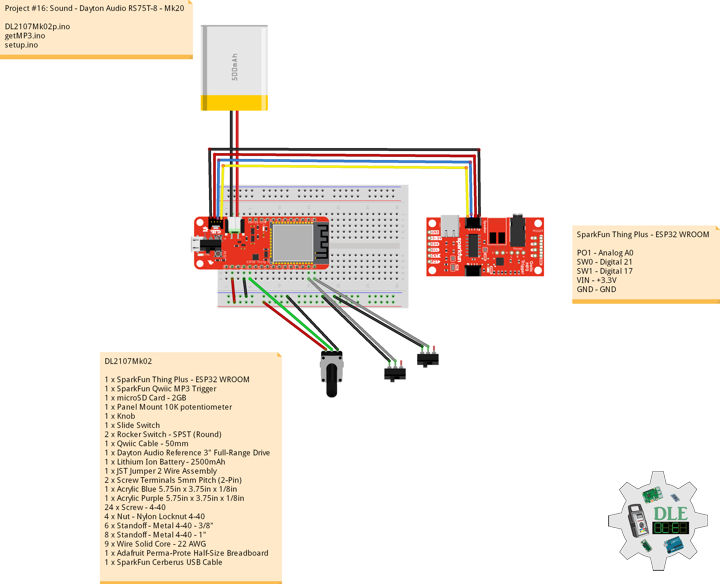
1 x SparkFun Thing Plus – ESP32 WROOM
1 x Adafruit SHARP Memory Display
1 x Adalogger FeatherWing – RTC + SD
1 x CR1220 3V Lithium Coin Cell Battery
1 x 32Gb microSD Card
1 x LED Green
1 x Rocker Switch – SPST (Round)
1 x Terminal Block Breakout FeatherWing
1 x Lithium Ion Battery – 850mAh
1 x GPS Receiver – GP-20U7
1 x Rotary Switch – 10 Position
1 x SparkFun Rotary Switch – 10 Position
1 x Black Knob
1 x Breadboard Solderable
12 x 1K Ohm
1 x Half-Size Breadboard
1 x SparkFun Cerberus USB Cable
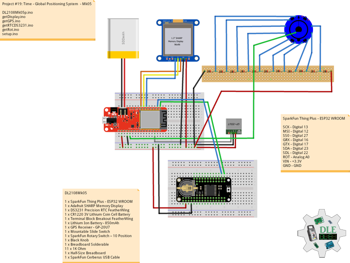
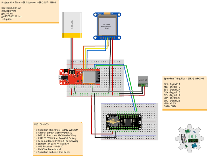
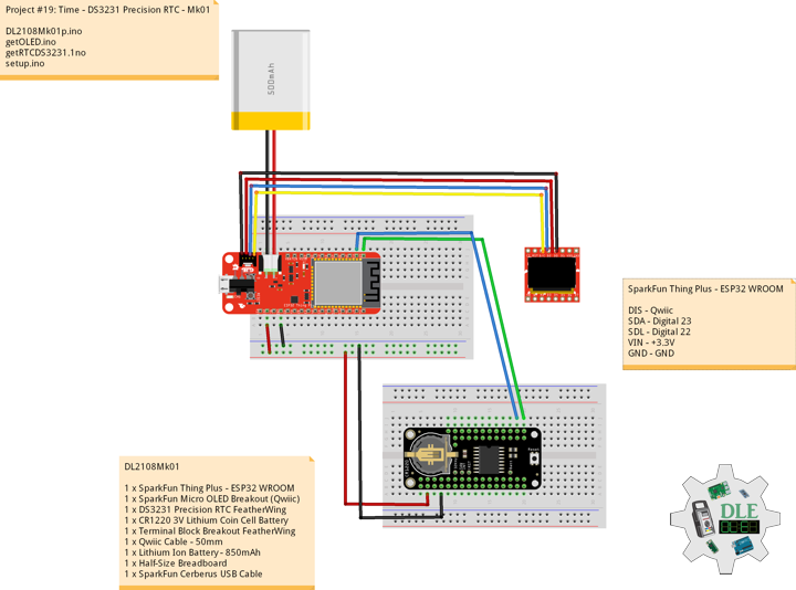
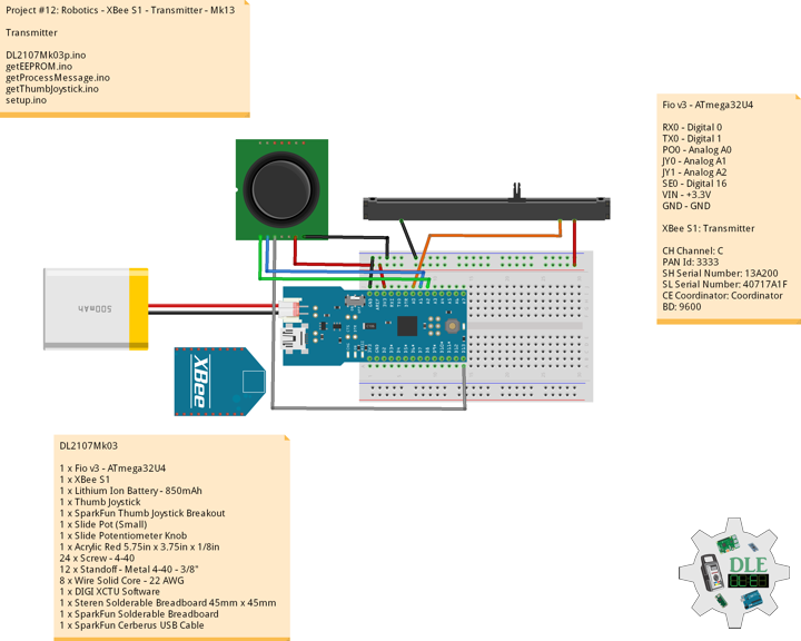
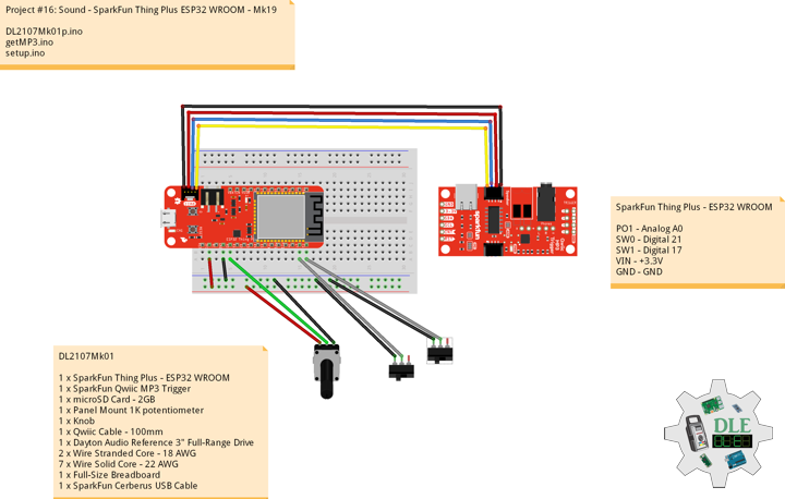
SparkFun Thing Plus – ESP32 WROOM
SCK – Digital 13
MSI – Digital 12
SS0 – Digital 27
GRX – Digital 16
GTX – Digital 17
SDA – Digital 23
SDL – Digital 22
SCK – Digital 5
MSO – Digital 19
MSI – Digital 18
SS1 – Digital 33
LEG – Digital 21
SW0 – Digital 32
ROT – Analog A0
VIN – +3.3V
GND – GND
DL2108Mk06p.ino
/*
***** Don Luc Electronics © *****
Software Version Information
Project #19: Time - Adalogger FeatherWing - RTC + SD - Mk05
08-06
DL2108Mk06p.ino
1 x SparkFun Thing Plus - ESP32 WROOM
1 x Adafruit SHARP Memory Display
1 x Adalogger FeatherWing - RTC + SD
1 x CR1220 3V Lithium Coin Cell Battery
1 x 32Gb microSD Card
1 x LED Green
1 x Rocker Switch - SPST (Round)
1 x Terminal Block Breakout FeatherWing
1 x Lithium Ion Battery - 850mAh
1 x GPS Receiver - GP-20U7
1 x Rotary Switch - 10 Position
1 x SparkFun Rotary Switch – 10 Position
1 x Black Knob
1 x Breadboard Solderable
12 x 1K Ohm
1 x Half-Size Breadboard
1 x SparkFun Cerberus USB Cable
*/

// Include the Library Code
// EEPROM Library to Read and Write EEPROM with Unique ID for Unit
#include "EEPROM.h"
// Wire
// #include <Wire.h>
// SHARP Memory Display
#include <Adafruit_SharpMem.h>
#include <Adafruit_GFX.h>
// Date and time RTC
#include "RTClib.h"
// GPS Receiver
#include <TinyGPS++.h>
// ESP32 Hardware Serial
#include <HardwareSerial.h>
// SD Card
#include "FS.h"
#include "SD.h"
#include "SPI.h"

// SHARP Memory Display
#define SHARP_SCK  13
#define SHARP_MOSI 12
#define SHARP_SS   27
// Set the size of the display here, e.g. 144x168!
Adafruit_SharpMem display(SHARP_SCK, SHARP_MOSI, SHARP_SS, 144, 168);
// The currently-available SHARP Memory Display (144x168 pixels)
// requires > 4K of microcontroller RAM; it WILL NOT WORK on Arduino Uno
// or other <4K "classic" devices.
#define BLACK 0
#define WHITE 1

// Date and Time
// PCF8523 Precision RTC
RTC_PCF8523 rtc;
// Date
String dateRTC = "";
// Time
String timeRTC = "";

// ESP32 HardwareSerial
HardwareSerial tGPS(2);

// GPS Receiver
#define gpsRXPIN 16
// This one is unused and doesnt have a conection
#define gpsTXPIN 17
// The TinyGPS++ object
TinyGPSPlus gps;
// Latitude
float TargetLat;
// Longitude
float TargetLon;
// GPS Date, Time, Speed, Altitude
// GPS Date
String TargetDat;
// GPS Time
String TargetTim;
// GPS Speeds M/S
String TargetSMS;
// GPS Speeds Km/h
String TargetSKH;
// GPS Altitude Meters
String TargetALT;
// GPS Status
String GPSSt = "";

// Rotary Switch - 10 Position
// Number 1 => 10
int iRotNum = A0;
// iRotVal - Value
int iRotVal = 0;
// Number
int z = 0;

// MicroSD Card
const int chipSelect = 33;
String zzzzzz = "";

// LED Green
int iLEDGreen = 21;

// Rocker Switch - SPST (Round)
int iSS1 = 32;
// State
int iSS1State = 0;

// Software Version Information
// EEPROM Unique ID Information
#define EEPROM_SIZE 64
String uid = "";
// Version
String sver = "19-05";

void loop()
{

  // Dates and Time
  isRTC();

  // isGPS
  isGPS();

  // Rotary Switch
  isRot();

  // Slide Switch
  // Read the state of the iSS1 value
  iSS1State = digitalRead(iSS1);

  // If it is the Slide Switch State is HIGH
  if (iSS1State == HIGH) {

    // iLEDGreen HIGH
    digitalWrite(iLEDGreen,  HIGH );

    // MicroSD Card
    isSD();

  } else {

    // iLEDGreen LOW
    digitalWrite(iLEDGreen,  LOW );

  }

  delay( 1000 );

}
getDisplay.ino
// SHARP Memory Display
// SHARP Memory Display - UID
void isDisplayUID() {
// Text Display
// Clear Display
display.clearDisplay();
display.setRotation(4);
display.setTextSize(3);
display.setTextColor(BLACK);
// Don Luc Electronics
display.setCursor(0,10);
display.println( "Don Luc" );
display.setTextSize(2);
display.setCursor(0,40);
display.println( "Electronics" );
// Version
//display.setTextSize(3);
display.setCursor(0,70);
display.println( "Version" );
//display.setTextSize(2);
display.setCursor(0,95);
display.println( sver );
// EEPROM
display.setCursor(0,120);
display.println( "EEPROM" );
display.setCursor(0,140);
display.println( uid );
// Refresh
display.refresh();
delay( 100 );
}
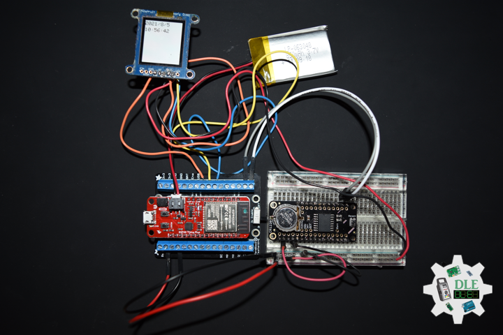
// Display Date
void isDisplayDate() {
// Text Display Date
// Clear Display
display.clearDisplay();
display.setRotation(4);
display.setTextSize(2);
display.setTextColor(BLACK);
// Date
display.setCursor(0,5);
display.println( "Date" );
display.setCursor(0,30);
display.println( dateRTC );
// Time
display.setCursor(0,55);
display.println( "Time" );
display.setCursor(0,75);
display.println( timeRTC );
// Refresh
display.refresh();
delay( 100 );
}
// Display GPS
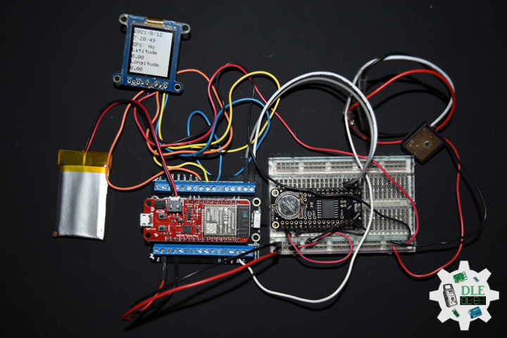
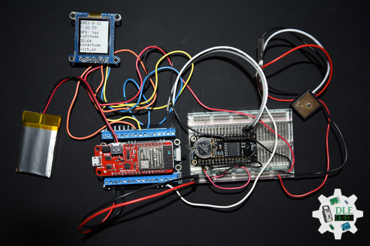
void isDisplayGPS() {
// Text Display Date
// Clear Display
display.clearDisplay();
display.setRotation(4);
display.setTextSize(2);
display.setTextColor(BLACK);
// GPS Status
display.setCursor(0,5);
display.print( "GPS: " );
display.println( GPSSt );
// Target Latitude
display.setCursor(0,25);
display.println( "Latitude" );
display.setCursor(0,45);
display.println( TargetLat );
// Target Longitude
display.setCursor(0,65);
display.println( "Longitude" );
display.setCursor(0,90);
display.println( TargetLon );
// Refresh
display.refresh();
delay( 100 );
}
// GPS Date, Time, Speed, Altitude
void isDisplayGPSDate() {
// Text Display Date
// Clear Display
display.clearDisplay();
display.setRotation(4);
display.setTextSize(2);
display.setTextColor(BLACK);
// GPS
display.setCursor(0,5);
display.println( "GPS" );
// Date
display.setCursor(0,30);
display.println( TargetDat );
// Time
display.setCursor(0,55);
display.println( TargetTim );
// Speed
display.setCursor(0,75);
display.print( "M/S: " );
display.println( TargetSMS );
display.setCursor(0,95);
display.print( "Km/h: " );
display.println( TargetSKH );
display.setCursor(0,115);
display.print( "Alt: " );
display.println( TargetALT );
// Refresh
display.refresh();
delay( 100 );
}
// Display Z
void isDisplayZ() {
// Text Display Z
// Clear Display
display.clearDisplay();
display.setRotation(4);
display.setTextSize(3);
display.setTextColor(BLACK);
// Z
display.setCursor(0,10);
display.print( "Z: " );
display.println( z );
// Refresh
display.refresh();
delay( 100 );
}
getEEPROM.ino
// EEPROM
// isUID EEPROM Unique ID
void isUID()
{

  // Is Unit ID
  uid = "";
  for (int x = 0; x < 5; x++)
  {
    uid = uid + char(EEPROM.read(x));
  }

}
getGPS.ino
// GPS Receiver
// Setup GPS
void setupGPS() {

  // Setup GPS
  tGPS.begin(  9600 , SERIAL_8N1 , gpsRXPIN , gpsTXPIN );

}
// isGPS
void isGPS(){

  // Receives NEMA data from GPS receiver
  // This sketch displays information every time a new sentence is correctly encoded
  while ( tGPS.available() > 0)

    if (gps.encode( tGPS.read() ))
    {

       // GPS Vector Pointer Target
       displayInfo();
       // GPS Date, Time, Speed, Altitude
       displayDTS();

    }

  if (millis() > 5000 && gps.charsProcessed() < 10)
  {

     while(true);

  }

}
// GPS Vector Pointer Target
void displayInfo(){

  // Location
  if (gps.location.isValid())
  {

     // Latitude
     TargetLat = gps.location.lat();
     // Longitude
     TargetLon = gps.location.lng();
     // GPS Status 2
     GPSSt = "Yes";

  }
  else
  {

     // GPS Status 0
     GPSSt = "No";

  }

}
// GPS Date, Time, Speed, Altitude
void displayDTS(){

  // Date
  TargetDat = "";
  if (gps.date.isValid())
  {

     // Date
     // Year
     TargetDat += String(gps.date.year(), DEC);
     TargetDat += "/";
     // Month
     TargetDat += String(gps.date.month(), DEC);
     TargetDat += "/";
     // Day
     TargetDat += String(gps.date.day(), DEC);

  }

  // Time
  TargetTim = "";
  if (gps.time.isValid())
  {

     // Time
     // Hour
     TargetTim += String(gps.time.hour(), DEC);
     TargetTim += ":";
     // Minute
     TargetTim += String(gps.time.minute(), DEC);
     TargetTim += ":";
     // Secound
     TargetTim += String(gps.time.second(), DEC);

  }

  // Speed
  TargetSMS = "";
  TargetSKH = "";
  if (gps.speed.isValid())
  {

     // Speed
     // M/S
     int x = gps.speed.mps();
     TargetSMS = String( x, DEC);
     // Km/h
     int y = gps.speed.kmph();
     TargetSKH = String( y, DEC);

  }

  // Altitude
  TargetALT = "";
  if (gps.altitude.isValid())
  {

     // Altitude
     // Meters
     int z = gps.altitude.meters();
     TargetALT = String( z, DEC);

  }

}
getRTC.ino
// Date & Time
// PCF8523 Precision RTC
void setupRTC() {

  // Date & Time
  // pcf8523 Precision RTC
  if (! rtc.begin()) {
    while (1);
  }

  if (! rtc.initialized()) {

    // Following line sets the RTC to the date & time this sketch was compiled
    rtc.adjust(DateTime(F(__DATE__), F(__TIME__)));
    // This line sets the RTC with an explicit date & time, for example to set
    // January 21, 2014 at 3am you would call:
    // rtc.adjust(DateTime(2014, 1, 21, 3, 0, 0));
    // rtc.adjust(DateTime(2021, 8, 16, 12, 27, 0));

  }

}
// Date and Time RTC PCF8523
void isRTC () {

  // Date and Time
  dateRTC = "";
  timeRTC = "";
  DateTime now = rtc.now();

  // Date
  // Year
  dateRTC = now.year(), DEC;
  dateRTC = dateRTC + "/";
  // Month
  dateRTC = dateRTC + now.month(), DEC;
  dateRTC = dateRTC + "/";
  // Day
  dateRTC = dateRTC + now.day(), DEC;

  // Time
  // Hour
  timeRTC = now.hour(), DEC;
  timeRTC = timeRTC + ":";
  // Minute
  timeRTC = timeRTC + now.minute(), DEC;
  timeRTC = timeRTC + ":";
  // Second
  timeRTC = timeRTC + now.second(), DEC;

}
getRot.ino
// Rotary Switch
// isRot - iRotVal - Value
void isRot() {

  // Rotary Switch
  z = analogRead( iRotNum );

  // Rotary Switch - 10 Position
  // Number 1 => 10
  if ( z >= 3500 ) {

    // Z
    iRotVal = 10;

  } else if ( z >= 3000 ) {

    // Z
    iRotVal = 9;

  } else if ( z >= 2600 ) {

    // Z
    iRotVal = 8;

  } else if ( z >= 2300 ) {

    // Z
    iRotVal = 7;

  } else if ( z >= 1900 ) {

    // Z
    iRotVal = 6;

  } else if ( z >= 1500 ) {

    // Z
    iRotVal = 5;

  } else if ( z >= 1200 ) {

    // Z
    iRotVal = 4;

  } else if ( z >= 800 ) {

    // Z
    iRotVal = 3;

  } else if ( z >= 400 ) {

    // Z
    iRotVal = 2;

  } else {

    // Z
    iRotVal = 1;

  }

  // Range Value
  switch ( iRotVal ) {
    case 1:

      // Display Date, Time
      isDisplayDate();

      break;
    case 2:

      // Display GPS
      isDisplayGPS();

      break;
    case 3:

      // GPS Date, Time, Speed, Altitude
      //isDisplayGPSDate();

      break;
    case 4:

      // GPS Display Date, Time, Speed
      isDisplayGPSDate();

      break;
    case 5:

      // Z
      isDisplayZ();

      break;
    case 6:

      // Z
      isDisplayZ();

      break;
    case 7:

      // Z
      isDisplayZ();

      break;
    case 8:

      // Z
      isDisplayZ();

      break;
    case 9:

      // Z
      isDisplayZ();

      break;
    case 10:

      // Z
      isDisplayZ();

      break;
  }

}
getSD.ino
// MicroSD Card
// MicroSD Setup
void setupSD() {

    // MicroSD Card
    pinMode( chipSelect , OUTPUT );
    if(!SD.begin( chipSelect )){
        ;
        return;
    }

    uint8_t cardType = SD.cardType();

    // CARD NONE
    if(cardType == CARD_NONE){
        ;
        return;
    }

    // SD Card Type
    if(cardType == CARD_MMC){
        ;
    } else if(cardType == CARD_SD){
        ;
    } else if(cardType == CARD_SDHC){
        ;
    } else {
        ;
    }

    // Size
    uint64_t cardSize = SD.cardSize() / (1024 * 1024);

}
// MicroSD Card
void isSD() {

  zzzzzz = "";

  // EEPROM Unique ID|Version|Date|Time|GPS Status|Target Latitude|Target Longitude|GPS Date|GPS Time|GPS Speed M/S|GPS Speed Km/h|GPS Altitude|\r
  zzzzzz = uid + "|" + sver + "|" + dateRTC + "|" + timeRTC + "|" + GPSSt + "|" + TargetLat + "|" + TargetLon + "|" + TargetDat + "|" + TargetTim + "|" + TargetSMS + "|" + TargetSKH + "|" + TargetALT + "|\r";

  // msg + 1
  char msg[zzzzzz.length() + 1];

  zzzzzz.toCharArray(msg, zzzzzz.length() + 1);

  // Append File
  appendFile(SD, "/espdata.txt", msg );

}
// List Dir
void listDir(fs::FS &fs, const char * dirname, uint8_t levels){

    // List Dir
    dirname;

    File root = fs.open(dirname);

    if(!root){
        return;
    }

    if(!root.isDirectory()){
        return;
    }

    File file = root.openNextFile();

    while(file){
        if(file.isDirectory()){
            file.name();
            if(levels){
                listDir(fs, file.name(), levels -1);
            }
        } else {
            file.name();
            file.size();
        }
        file = root.openNextFile();
    }

}
// Write File
void writeFile(fs::FS &fs, const char * path, const char * message){

    // Write File
    path;

    File file = fs.open(path, FILE_WRITE);

    if(!file){
        return;
    }

    if(file.print(message)){
        ;
    } else {
        ;
    }

    file.close();

}
// Append File
void appendFile(fs::FS &fs, const char * path, const char * message){

    // Append File
    path;

    File file = fs.open(path, FILE_APPEND);

    if(!file){
        return;
    }

    if(file.print(message)){
        ;
    } else {
        ;
    }

    file.close();

}
setup.ino
// Setup
void setup()
{

  // EEPROM Size
  EEPROM.begin(EEPROM_SIZE);

  // EEPROM Unique ID
  isUID();

  // GPS Receiver
  // Setup GPS
  setupGPS();

  // Set up I2C bus
  // Wire.begin();

  // SHARP Display Start & Clear the Display
  display.begin();
  // Clear Display
  display.clearDisplay();

  // Date & Time RTC
  // PCF8523 Precision RTC
  isDisplayUID();

  // Setup RTC
  setupRTC();

  //MicroSD Card
  setupSD();

  // Initialize the LED Green
  pinMode(iLEDGreen, OUTPUT);

  // Slide Switch
  pinMode(iSS1, INPUT);

  delay( 5000 );

}
——
People can contact us: https://www.donluc.com/?page_id=1927
Technology Experience
- Single-Board Microcontrollers (PIC, Arduino, Raspberry Pi,Espressif, etc…)
- IoT
- Robotics
- Research & Development (R & D)
- Desktop Applications (Windows, OSX, Linux, Multi-OS, Multi-Tier, etc…)
- Mobile Applications (Android, iOS, Blackberry, Windows Mobile, Windows CE, etc…)
- Web Applications (LAMP, Scripting, Java, ASP, ASP.NET, RoR, Wakanda, etc…)
- Social Media Programming & Integration (Facebook, Twitter, YouTube, Pinterest, etc…)
- Content Management Systems (WordPress, Drupal, Joomla, Moodle, etc…)
- Bulletin Boards (phpBB, SMF, Vanilla, jobberBase, etc…)
- eCommerce (WooCommerce, OSCommerce, ZenCart, PayPal Shopping Cart, etc…)
Instructor
- PIC Microcontrollers
- Arduino
- Raspberry Pi
- Espressif
- Robotics
- DOS, Windows, OSX, Linux, iOS, Android, Multi-OS
- Linux-Apache-PHP-MySQL
Follow Us
J. Luc Paquin – Curriculum Vitae – 2021 English & Español
https://www.jlpconsultants.com/CV/LucPaquinCVEngMk2021c.pdf
https://www.jlpconsultants.com/CV/LucPaquinCVEspMk2021c.pdf
Web: https://www.donluc.com/
Web: https://www.jlpconsultants.com/
Web: https://www.donluc.com/DLE/
Web: https://www.donluc.com/DLHackster/
Web: https://www.hackster.io/neosteam-labs
Web: https://zoom.us/
Patreon: https://www.patreon.com/DonLucElectronics
Facebook: https://www.facebook.com/neosteam.labs.9/
YouTube: https://www.youtube.com/channel/UC5eRjrGn1CqkkGfZy0jxEdA
Twitter: https://twitter.com/labs_steam
Pinterest: https://www.pinterest.com/NeoSteamLabs/
Instagram: https://www.instagram.com/neosteamlabs/
Don Luc