——
#DonLucElectronics #DonLuc #RadioFrequency #Bluetooth #Gamepad #SparkFunThingPlusESP32WROOM #Arduino #Project #Fritzing #Programming #Electronics #Microcontrollers #Consultant
——
——
——
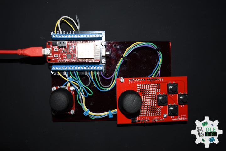
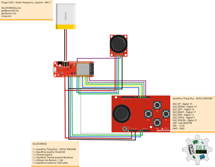
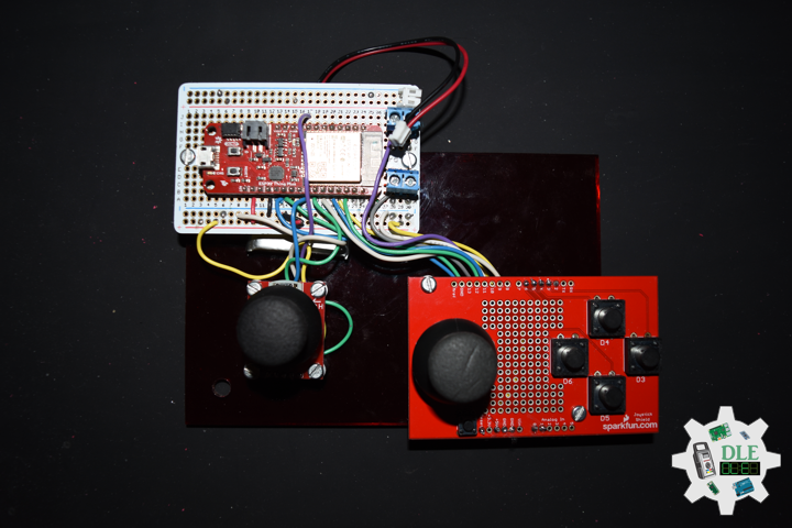
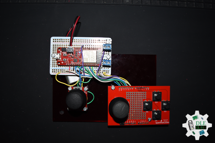
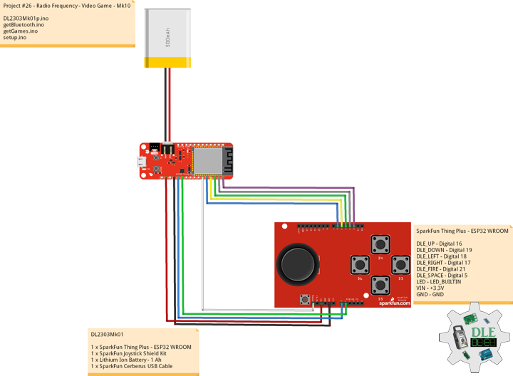
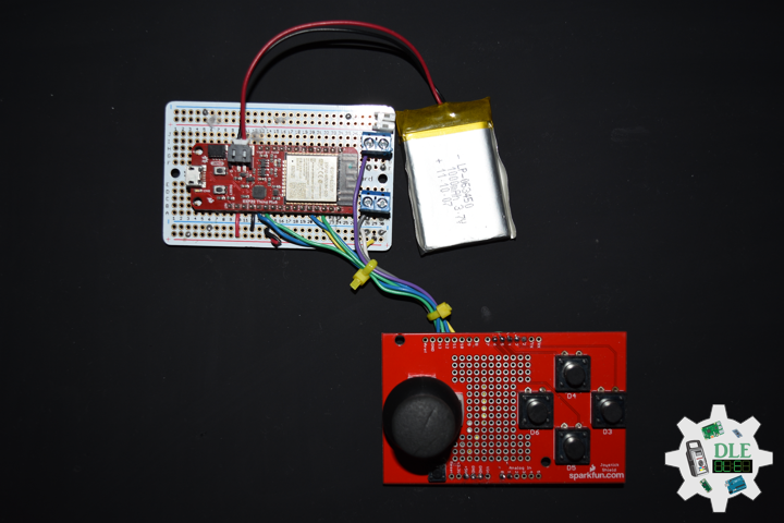
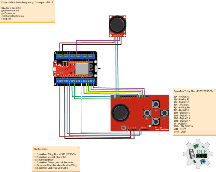
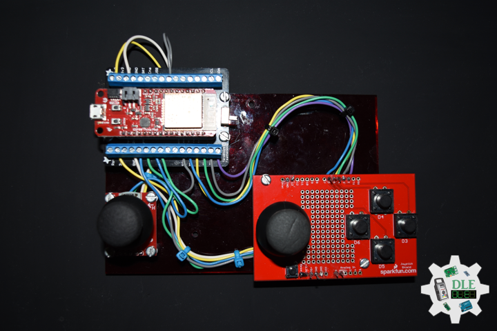
Gamepad
A gamepad is a type of video game controller held in two hands, where the fingers are used to provide input. They are typically the main input device for video game consoles. Gamepads generally feature a set of buttons handled with the right thumb and a direction controller handled with the left. The direction controller has traditionally been a four-way digital cross, also named a joypad, or alternatively a D-pad, and never called arrow keys, but most modern controllers additionally feature one or more analog sticks.
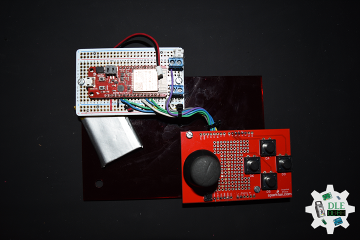
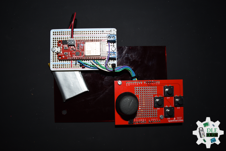
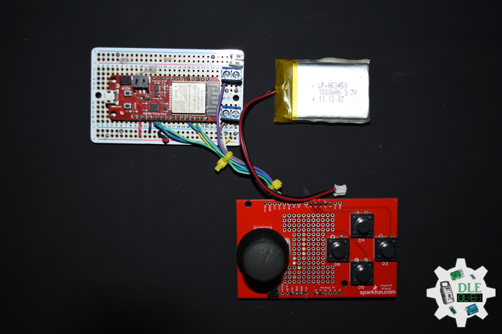
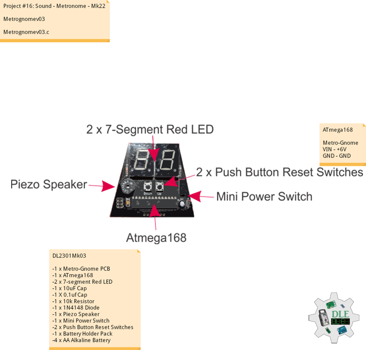
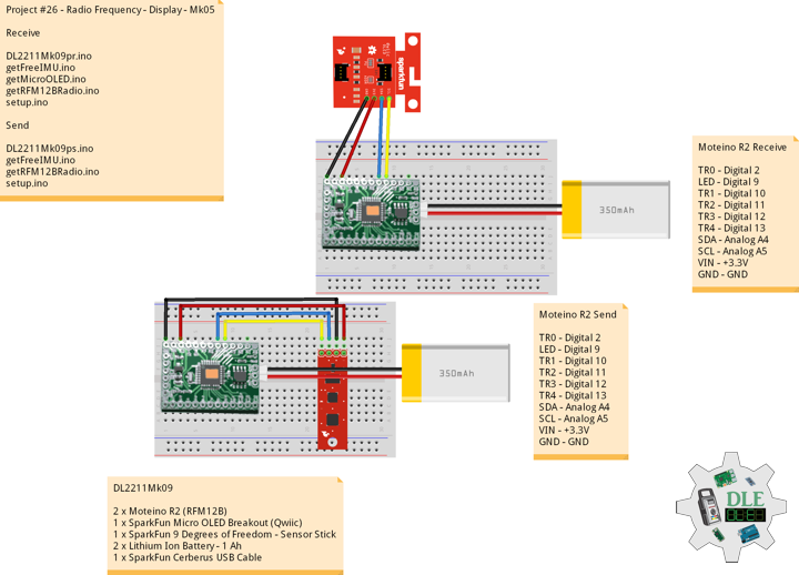
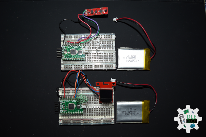
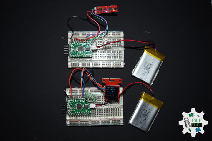
DL2303Mk03
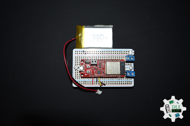
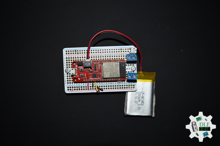
1 x SparkFun Thing Plus – ESP32 WROOM
1 x SparkFun Joystick Shield Kit
1 x Thumb Joystick
1 x SparkFun Thumb Joystick Breakout
1 x Terminal Block Breakout FeatherWing
1 x SparkFun Cerberus USB Cable
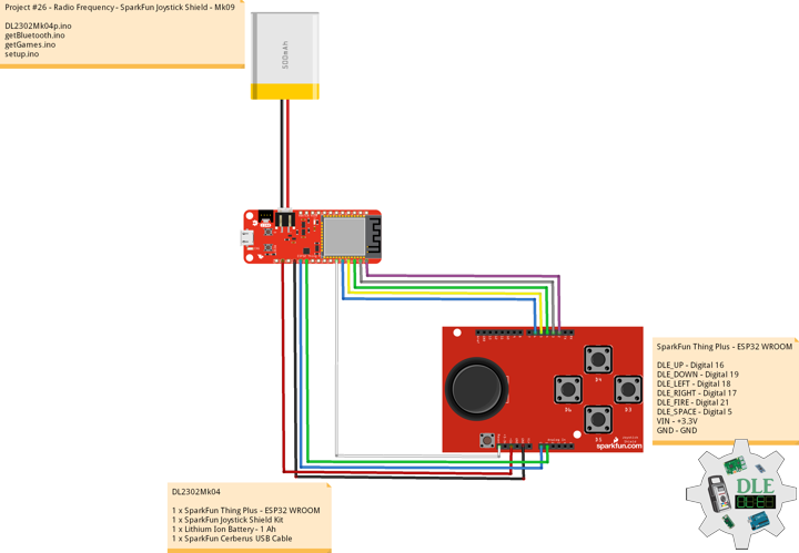
SparkFun Thing Plus – ESP32 WROOM
LJH – Analog A3
LJV – Analog A2
LJS – Digital 12
RJH – Analog A1
RJV – Analog A0
RJS – Digital 21
LD1 – Digital 16
LD2 – Digital 18
LD3 – Digital 19
LD4 – Digital 17
LT – Digital 5
LED – LED_BUILTIN
VIN – +3.3V
GND – GND
——
DL2303Mk03p.ino
/* ***** Don Luc Electronics © *****
Software Version Information
Project #26 - Radio Frequency - Gamepad - Mk12
26-12
DL2303Mk03p.ino
1 x SparkFun Thing Plus - ESP32 WROOM
1 x SparkFun Joystick Shield Kit
1 x Thumb Joystick
1 x SparkFun Thumb Joystick Breakout
1 x Terminal Block Breakout FeatherWing
1 x SparkFun Cerberus USB Cable
*/

// Include the Library Code
// Arduino
#include <Arduino.h>
// ESP32 BLE Gamepad
#include <BleGamepad.h>

// ESP32 BLE Gamepad
BleGamepad bleGamepad;

// Left Joystick
#define LJH A3
#define LJV A2
#define LJS 12

// Right Joystick
#define RJH A1
#define RJV A0
#define RJS 21

// D-pad
#define LD1 16
#define LD2 18
#define LD3 19
#define LD4 17

// LT
#define LT 5

// Number of pot samples to take (to smooth the values)
const int numberOfPotSamples = 5;
// Delay in milliseconds between pot samples
const int delayBetweenSamples = 2;
// Additional delay in milliseconds between HID reports
const int delayBetweenHIDReports = 5;
// Delay in milliseconds between button press
const int debounceDelay = 10;

// Software Version Information
String sver = "26-12";

void loop() {

  // Bluetooth Serial (ESP32SPP)
  isBluetooth();

  // Delay
  delay(500);

}
getBluetooth.ino
// Bluetooth
// isBluetooth
void isBluetooth() {

  // ESP32 BLE Gamepad
  if(bleGamepad.isConnected())
  {

    // Button
    isButton();

    // Joystick
    isThumbJoystick();

    // Serial
    Serial.println(" *");

  }

}
getGames.ino
// Games
// Set Inputs
void setInputs() {

  // Make the button line an input
  pinMode(LJS, INPUT_PULLUP);
  pinMode(RJS, INPUT_PULLUP);
  pinMode(LD1, INPUT_PULLUP);
  pinMode(LD2, INPUT_PULLUP);
  pinMode(LD3, INPUT_PULLUP);
  pinMode(LD4, INPUT_PULLUP);
  pinMode(LT, INPUT_PULLUP);

  // Initialize digital pin LED_BUILTIN as an output.
  pinMode(LED_BUILTIN, OUTPUT);
  // Turn the LED on HIGH
  digitalWrite(LED_BUILTIN, HIGH);

}

// Button
void isButton(){

  // Left Joystick
  if (digitalRead(LJS) == LOW) {

    bleGamepad.press(LJS);
    delay(debounceDelay);
    bleGamepad.release(LJS);
    Serial.print(" LJS");

  }

  // Right Joystick
  if (digitalRead(RJS) == LOW) {

    bleGamepad.press(RJS);
    delay(debounceDelay);
    bleGamepad.release(RJS);
    Serial.print(" RJS");

  }

  // LT
  if (digitalRead(LT) == LOW) {

    bleGamepad.press(LT);
    delay(debounceDelay);
    bleGamepad.release(LT);
    Serial.print(" LT");

  }

}
getThumbJoystick.ino
// Thumb Joystick
void isThumbJoystick() {

  // Joystick LJH
  // Joystick Pot Values LJH
  int potValues[numberOfPotSamples];
  for (int i = 0 ; i < numberOfPotSamples ; i++) {

    potValues[i] = analogRead(LJH);
    delay(delayBetweenSamples);

  }
  int potValue = 0;
  for (int i = 0 ; i < numberOfPotSamples ; i++) {

    potValue += potValues[i];

  }
  // Value / Pot Samples
  potValue = potValue / numberOfPotSamples;
  // Serial
  Serial.print(" LJH: ");
  Serial.print(potValue);
  // Adjusted Value
  int adjustedValue = map(potValue, 0, 4095, 127, -127);

  // Joystick LJV
  // Joystick Pot Values LJV
  int potValues2[numberOfPotSamples];
  for (int i = 0 ; i < numberOfPotSamples ; i++) {

    potValues2[i] = analogRead(LJV);
    delay(delayBetweenSamples);

  }
  int potValue2 = 0;
  for (int i = 0 ; i < numberOfPotSamples ; i++) {

    potValue2 += potValues2[i];

  }
  // Value2 / Pot Samples
  potValue2 = potValue2 / numberOfPotSamples;
  // Serial
  Serial.print(" LJV: ");
  Serial.print(potValue2);
  // Adjusted Value2
  int adjustedValue2 = map(potValue2, 0, 4095, 127, -127);

  // Joystick RJH
  // Joystick Pot Values RJH
  int potValues3[numberOfPotSamples];
  for (int i = 0 ; i < numberOfPotSamples ; i++) {

    potValues3[i] = analogRead(RJH);
    delay(delayBetweenSamples);

  }
  int potValue3 = 0;
  for (int i = 0 ; i < numberOfPotSamples ; i++) {

      potValue3 += potValues3[i];

  }
  // Value3 / Pot Samples
  potValue3 = potValue3 / numberOfPotSamples;
  // Serial
  Serial.print(" RJH: ");
  Serial.print(potValue3);
  // Adjusted Value3
  int adjustedValue3 = map(potValue3, 0, 4095, 255, 0);

  // Joystick RJV
  // Joystick Pot Values RJV
  int potValues4[numberOfPotSamples];
  for (int i = 0 ; i < numberOfPotSamples ; i++) {

    potValues4[i] = analogRead(RJV);
    delay(delayBetweenSamples);

  }
  int potValue4 = 0;
  for (int i = 0 ; i < numberOfPotSamples ; i++) {

      potValue4 += potValues4[i];

  }
  // Value4 / Pot Samples
  potValue4 = potValue4 / numberOfPotSamples;
  // Serial
  Serial.print(" RJV: ");
  Serial.print(potValue4);
  // Adjusted Value4
  int adjustedValue4 = map(potValue4, 0, 4095, 255, 0);

  bleGamepad.setAxes(adjustedValue, adjustedValue2, 0, 0, adjustedValue3, adjustedValue4, DPAD_CENTERED);
  delay(delayBetweenHIDReports);

  // D-pad
  // LD1
  if (digitalRead(LD1) == LOW){

    bleGamepad.setAxes(adjustedValue, adjustedValue2, 0, 0, adjustedValue3, adjustedValue4, DPAD_UP);
    Serial.print(" DPAD_UP");

  }

  // LD2
  if (digitalRead(LD2) == LOW){

    bleGamepad.setAxes(adjustedValue, adjustedValue2, 0, 0, adjustedValue3, adjustedValue4, DPAD_LEFT);
    Serial.print(" DPAD_LEFT");

  }

  // LD3
  if (digitalRead(LD3) == LOW){

    bleGamepad.setAxes(adjustedValue, adjustedValue2, 0, 0, adjustedValue3, adjustedValue4, DPAD_DOWN);
    Serial.print(" DPAD_DOWN");

  }

  // LD4
  if (digitalRead(LD4) == LOW){

    bleGamepad.setAxes(adjustedValue, adjustedValue2, 0, 0, adjustedValue3, adjustedValue4, DPAD_RIGHT);
    Serial.print(" DPAD_RIGHT");

  }

}
setup.ino
// Setup
void setup()
{

  // Serial
  Serial.begin(115200);
  Serial.println("Starting BLE work!");

  // Set Inputs
  setInputs();

  // ESP32 BLE Gamepad
  bleGamepad.begin();

}
——
People can contact us: https://www.donluc.com/?page_id=1927
Technology Experience
- Programming Language
- Single-Board Microcontrollers (PIC, Arduino, Raspberry Pi,Espressif, etc…)
- IoT
- Wireless (Radio Frequency, Bluetooth, WiFi, Etc…)
- Robotics
- Camera and Video Capture Receiver Stationary, Wheel/Tank and Underwater Vehicle
- Unmanned Vehicles Terrestrial and Marine
- Machine Learning
- RTOS
- Research & Development (R & D)
Instructor, E-Mentor, STEAM, and Arts-Based Training
- Programming Language
- IoT
- PIC Microcontrollers
- Arduino
- Raspberry Pi
- Espressif
- Robotics
Follow Us
Luc Paquin – Curriculum Vitae – 2023
https://www.donluc.com/luc/
Web: https://www.donluc.com/
Facebook: https://www.facebook.com/neosteam.labs.9/
YouTube: https://www.youtube.com/@thesass2063
Twitter: https://twitter.com/labs_steam
Pinterest: https://www.pinterest.com/NeoSteamLabs/
Instagram: https://www.instagram.com/neosteamlabs/
Don Luc