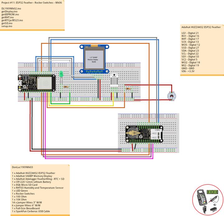
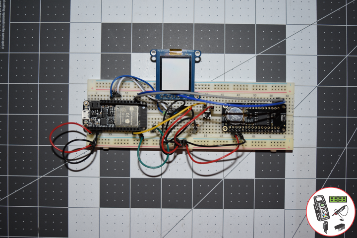
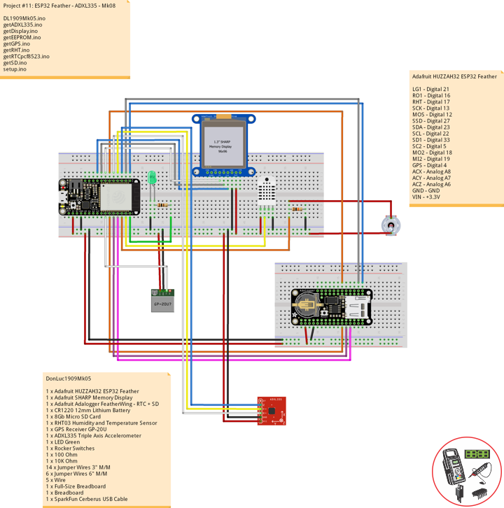
ESP32 Feather – ADXL335
——
——
——
——
——
——
ADXL335 Triple Axis Accelerometer
Breakout board for the 3 axis ADXL335 from Analog Devices. This is the latest in a long, proven line of analog sensors – the holy grail of accelerometers. The ADXL335 is a triple axis MEMS accelerometer with extremely low noise and power consumption – only 320uA! The sensor has a full sensing range of +/-3g.
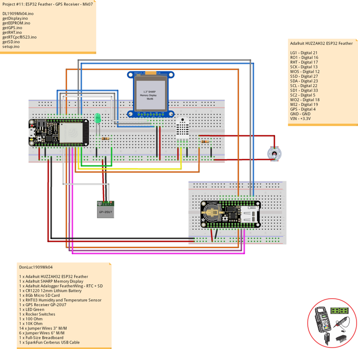
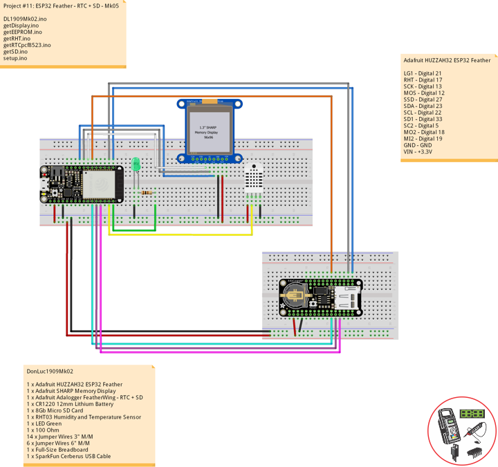
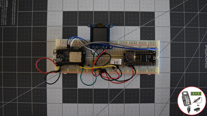
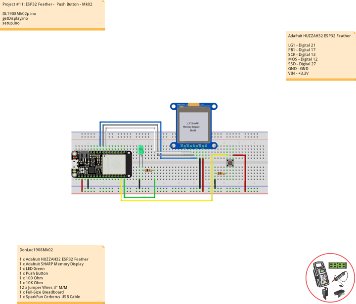
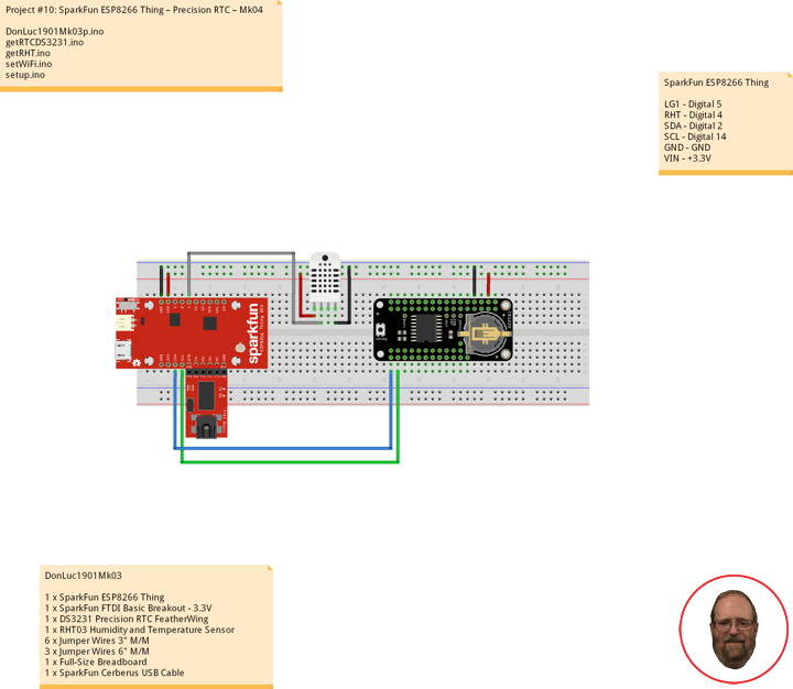
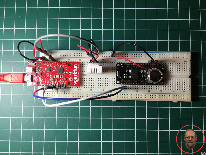
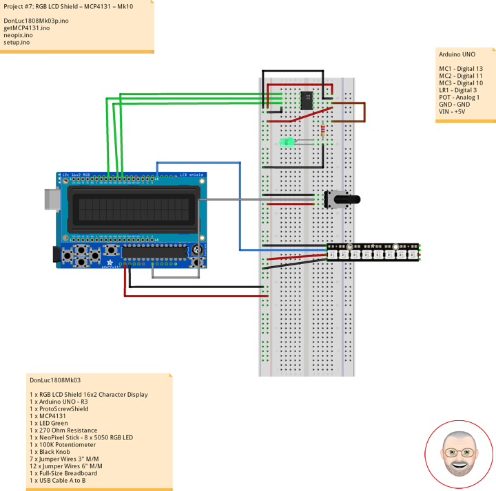
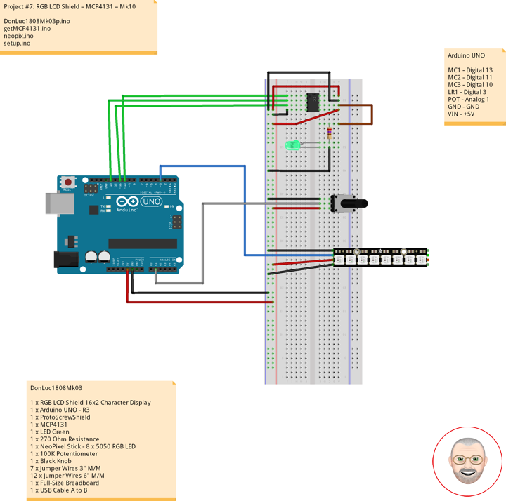
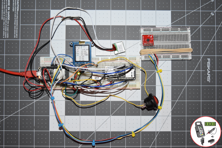
DonLuc1909Mk05
1 x Adafruit HUZZAH32 ESP32 Feather
1 x Adafruit SHARP Memory Display
1 x Adafruit Adalogger FeatherWing – RTC + SD
1 x CR1220 12mm Lithium Battery
1 x 8Gb Micro SD Card
1 x RHT03 Humidity and Temperature Sensor
1 x GPS Receiver GP-20U
1 x ADXL335 Triple Axis Accelerometer
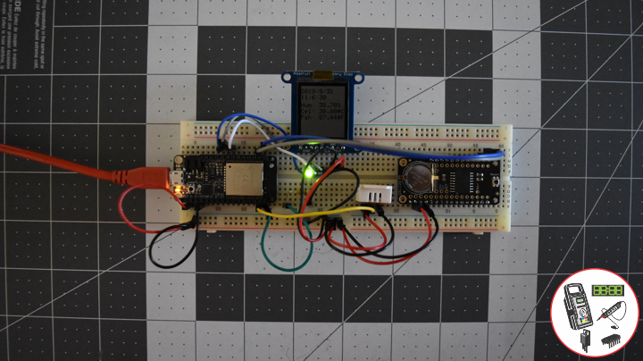
1 x LED Green
1 x Rocker Switches
1 x 100 Ohm
1 x 10K Ohm
14 x Jumper Wires 3″ M/M
6 x Jumper Wires 6″ M/M
5 x Wire
1 x Full-Size Breadboard
1 x Breadboard
1 x SparkFun Cerberus USB Cable
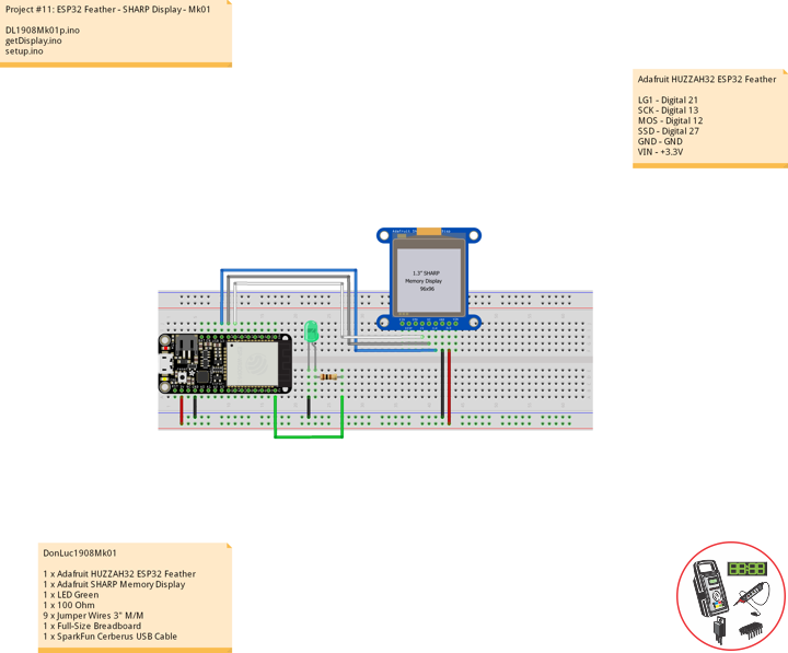
Adafruit HUZZAH32 ESP32 Feather
LG1 – Digital 21
RO1 – Digital 16
RHT – Digital 17
SCK – Digital 13
MOS – Digital 12
SSD – Digital 27
SDA – Digital 23
SCL – Digital 22
SD1 – Digital 33
SC2 – Digital 5
MO2 – Digital 18
MI2 – Digital 19
GPS – Digital 4
ACX – Analog A8
ACY – Analog A7
ACZ – Analog A6
GND – GND
VIN – +3.3V
DL1909Mk05.ino
// ***** Don Luc Electronics *****
// Software Version Information
// Project #11: HUZZAH32 ESP32 Feather - ADXL335 - Mk08
// 09-05
// DL1909Mk05p.ino 11-08
// Adafruit HUZZAH32 ESP32 Feather Board
// SHARP Display
// LED Green
// Adalogger FeatherWing - RTC + SD
// EEPROM
// RHT03 Humidity and Temperature Sensor
// Rocker Switches
// GPS Receiver
// ADXL335 Triple Axis Accelerometer

// include Library Code
// SHARP Memory Display
#include <Adafruit_SharpMem.h>
#include <Adafruit_GFX.h>
// Date and Time
#include "RTClib.h"
// EEPROM library to read EEPROM with unique ID for unit
#include "EEPROM.h"
// RHT Humidity and Temperature Sensor
#include <SparkFun_RHT03.h>
// SD Card
#include "FS.h"
#include "SD.h"
#include "SPI.h"
// GPS Receiver
#include <TinyGPS++.h>
#include <HardwareSerial.h>
// ADXL335 Triple Axis Accelerometer
#include <ADXL335.h>

// SHARP Memory Display
// any pins can be used
#define SHARP_SCK  13
#define SHARP_MOSI 12
#define SHARP_SS   27
// Set the size of the display here, e.g. 144x168!
Adafruit_SharpMem display(SHARP_SCK, SHARP_MOSI, SHARP_SS, 144, 168);
// The currently-available SHARP Memory Display (144x168 pixels)
// requires > 4K of microcontroller RAM; it WILL NOT WORK on Arduino Uno
// or other <4K "classic" devices!
#define BLACK 0
#define WHITE 1
int minorHalfSize; // 1/2 of lesser of display width or height

// LED Green
int iLEDGreen =  21;                 // LED Green

// PCF8523 Precision RTC
RTC_PCF8523 rtc;
String dateRTC = "";
String timeRTC = "";

// RHT Humidity and Temperature Sensor
const int RHT03_DATA_PIN = 17;          // RHT03 data pin Digital 17
RHT03 rht;                              // This creates a RTH03 object, which we'll use to interact with the sensor
float latestHumidity;
float latestTempC;
float latestTempF;

// SD Card
const int chipSelect = 33;              // SD Card
String zzzzzz = "";

// Rocker Switches
int iRow1 = 16;                         // Rocker Switches Digital 16
int iRow1State = 0;                     // Variable for reading the pushbutton status

// ESP32 HardwareSerial
HardwareSerial tGPS(2);

// GPS Receiver
#define gpsRXPIN 4
#define gpsTXPIN 36                     // This one is unused and doesnt have a conection
// The TinyGPS++ object
TinyGPSPlus gps;
float TargetLat;
float TargetLon;
int Status = 0;

// ADXL335 Triple Axis Accelerometer
const int pin_x = A8;
const int pin_y = A7;
const int pin_z = A6;
const float aref = 3.3;
ADXL335 accel(pin_x, pin_y, pin_z, aref);
String latestX = "";
String latestY = "";
String latestZ = "";

// The current address in the EEPROM (i.e. which byte
// we're going to  read to next)
#define EEPROM_SIZE 64
String sver = "9-5.p";
// Unit ID information
String uid = "";

void loop() {

  // Receives NEMA data from GPS receiver
  // This sketch displays information every time a new sentence is correctly encoded.
  while ( tGPS.available() > 0)
    if (gps.encode( tGPS.read() ))
    {
     displayInfo();
    }

  if (millis() > 5000 && gps.charsProcessed() < 10)
  {
    while(true);
  }

  // Date and Time
  isRTC();

  // RHT03 Humidity and Temperature Sensor
  isRHT03();

  // SHARP Memory Display On
  isDisplayOn();

  // Rocker Switched
  // Read the state of the iRow1 value
  iRow1State = digitalRead(iRow1);

  // ADXL335 Triple Axis Accelerometer
  getADXL335();

  // Check if the pushbutton is pressed. If it is, the buttonState is HIGH:
  if (iRow1State == HIGH) {

    // iLEDGreen
    digitalWrite(iLEDGreen,  HIGH );
    // SD Card
    isSD();

  } else {

    // iLEDGreen
    digitalWrite(iLEDGreen,  LOW );

  }

  // Delay
  delay( 1000 );

}
getADXL335.ino
// ADXL335 Triple Axis Accelerometer
void getADXL335()
{

  // This is required to update the values
  accel.update();

  // This tells us how long the string is
  int string_width;

  float x;
  float y;
  float z;

  x = accel.getX();
  y = accel.getY();
  // If the project is laying flat and top up the z axis reads ~1G
  z = accel.getZ();

  latestX = formatFloat(x, 2, &string_width);
  latestY = formatFloat(y, 2, &string_width);
  latestZ = formatFloat(z, 2, &string_width);

}
// Format float library
String formatFloat(double value, int places, int* string_width)
{

  // If value is positive infinity
  if (isinf(value) > 0)
  {
    return "+Inf";
  }

  // Arduino does not seem to have negative infinity
  // keeping this code block for reference
  // if value is negative infinity
  if(isinf(value) < 0)
  {
    return "-Inf";
  }

  // If value is not a number
  if(isnan(value) > 0)
  {
    return "NaN";
  }

  // Always include a space for the dot
  int num_width = 1;

  // If the number of decimal places is less than 1
  if (places < 1)
  {

    // Set places to 1
    places = 1;

    // And truncate the value
    value = (float)((int)value);

  }

  // Add the places to the right of the decimal
  num_width += places;

  // If the value does not contain an integral part
  if (value < 1.0 && value > -1.0)
  {

    // Add one for the integral zero
    num_width++;

  }
  else
  {

    // Get the integral part and get the number of places to the left of decimal
    num_width += ((int)log10(abs(value))) + 1;

  }

  // If the value in less than 0
  if (value < 0.0)
  {

    // Add a space for the minus sign
    num_width++;

  }

  // Make a string the size of the number plus 1 for string terminator
  char s[num_width + 1];

  // Put the string terminator at the end
  s[num_width] = '\0';

  // Initalize the array to all zeros
  for (int i = 0; i < num_width; i++)
  {

    s[i] = '0';

  }

  // Characters that are not changed by the function below will be zeros
  // set the out variable string width lets the caller know what we came up with
  *string_width = num_width;

  // Use the avr-libc function dtosrtf to format the value
  return String(dtostrf(value,num_width,places,s));

}
getDisplay.ino
// SHARP Memory Display On
void isDisplayOn() {
// Clear Display
display.clearDisplay();
// text display date, time, LED on
display.setRotation(4);
display.setTextSize(2);
display.setTextColor(BLACK);
display.setCursor(0,1);
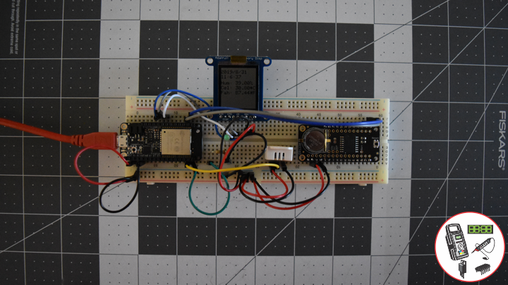
display.println( dateRTC );
display.setCursor(0,17);
display.println( timeRTC );
//display.setTextSize(2);
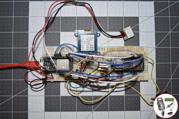
display.setCursor(0,35);
display.print("Lon: ");
display.println( TargetLon );
display.setCursor(0,55);
display.print("Lat: ");
display.println( TargetLat );
display.setCursor(0,74);
display.print("Hum: ");
display.print( latestHumidity );
display.println("%");
display.setCursor(0,94);
display.print("Cel: ");
display.print( latestTempC );
display.println("*C");
display.setCursor(0,114);
display.print("X: ");
display.println( latestX );
display.setCursor(0,134);
display.print("Y: ");
display.println( latestY );
display.setCursor(0,154);
display.print("Z: ");
display.println( latestZ );
display.refresh();
}
// SHARP Memory Display - UID
void isDisplayUID() {
// text display EEPROM
display.setRotation(4);
display.setTextSize(2);
display.setTextColor(BLACK);
display.setCursor(0,20);
display.print( "UID: " );
display.println( uid );
// display.setTextSize();
display.setTextColor(BLACK);
display.setCursor(0,45);
display.print( "VER: ");
display.println( sver );
display.refresh();
delay( 100 );
}
getEEPROM.ino
// EEPROM
void GetUID()
{

  // Get unit ID
  uid = "";
  for (int x = 0; x < 5; x++)
  {
    uid = uid + char(EEPROM.read(x));
  }

}
getGPS.ino
// GPS Receiver
void setupGPS() {

  // Setup GPS
  tGPS.begin(  9600 , SERIAL_8N1, gpsRXPIN, gpsTXPIN );

}
// GPS Vector Pointer Target
void displayInfo()
{

  // Location
  if (gps.location.isValid())
  {

    TargetLat = gps.location.lat();
    TargetLon = gps.location.lng();
    Status = 2;

  }
  else
  {

    Status = 0;

  }

}
getRHT.ino
// RHT03 Humidity and Temperature Sensor
void isRHT03(){

  // Call rht.update() to get new humidity and temperature values from the sensor.
  int updateRet = rht.update();

  // The humidity(), tempC(), and tempF() functions can be called -- after
  // a successful update() -- to get the last humidity and temperature value
  latestHumidity = rht.humidity();
  latestTempC = rht.tempC();
  latestTempF = rht.tempF();

}
getRTCpcf8523.ino
// PCF8523 Precision RTC
void setupRTC() {

  // pcf8523 Precision RTC
  if (! rtc.begin()) {
    while (1);
  }
  if (! rtc.initialized()) {
    // Following line sets the RTC to the date & time this sketch was compiled
    rtc.adjust(DateTime(F(__DATE__), F(__TIME__)));
    // This line sets the RTC with an explicit date & time, for example to set
    // January 21, 2014 at 3am you would call:
    // rtc.adjust(DateTime(2018, 9, 29, 12, 17, 0));
  }

}
// Date and Time RTC
void isRTC () {

  // Date and Time
  DateTime now = rtc.now();
  // Date
  dateRTC = now.year(), DEC;
  dateRTC = dateRTC + "/";
  dateRTC = dateRTC + now.month(), DEC;
  dateRTC = dateRTC + "/";
  dateRTC = dateRTC + now.day(), DEC;
  // Time
  timeRTC = now.hour(), DEC;
  timeRTC = timeRTC + ":";
  timeRTC = timeRTC + now.minute(), DEC;
  timeRTC = timeRTC + ":";
  timeRTC = timeRTC + now.second(), DEC;

}
getSD.ino
// SD Card
void setupSD() {

  // SD Card
    pinMode( chipSelect , OUTPUT );
    if(!SD.begin( chipSelect )){
        ;
        return;
    }
    uint8_t cardType = SD.cardType();

    if(cardType == CARD_NONE){
        ;
        return;
    }

    //Serial.print("SD Card Type: ");
    if(cardType == CARD_MMC){
        ;
    } else if(cardType == CARD_SD){
        ;
    } else if(cardType == CARD_SDHC){
        ;
    } else {
        ;
    }

    uint64_t cardSize = SD.cardSize() / (1024 * 1024);

}
// SD Card
void isSD() {

  zzzzzz = "";

  zzzzzz = uid + "|" + sver + "|" + dateRTC + "|" + timeRTC + "|" + Status + "|" + TargetLon + "|" + TargetLat + "|" + latestHumidity + "|" + latestTempC + "|" + latestTempF + "|" + latestX + "|" + latestY + "|" + latestZ + "|\r";

  char msg[zzzzzz.length() + 1];

  zzzzzz.toCharArray(msg, zzzzzz.length() + 1);

  appendFile(SD, "/espdata.txt", msg );

}
// List Dir
void listDir(fs::FS &fs, const char * dirname, uint8_t levels){
    dirname;
    File root = fs.open(dirname);
    if(!root){
        return;
    }
    if(!root.isDirectory()){
        return;
    }

    File file = root.openNextFile();
    while(file){
        if(file.isDirectory()){
            file.name();
            if(levels){
                listDir(fs, file.name(), levels -1);
            }
        } else {
            file.name();
            file.size();
        }
        file = root.openNextFile();
    }
}
// Write File
void writeFile(fs::FS &fs, const char * path, const char * message){
    path;
    File file = fs.open(path, FILE_WRITE);
    if(!file){
        return;
    }
    if(file.print(message)){
        ;
    } else {
        ;
    }
    file.close();
}
// Append File
void appendFile(fs::FS &fs, const char * path, const char * message){
    //Serial.printf("Appending to file: %s\n", path);
    path;
    File file = fs.open(path, FILE_APPEND);
    if(!file){
        return;
    }
    if(file.print(message)){
        ;
    } else {
        ;
    }
    file.close();
}
setup.ino
// Setup
void setup() {

  // EEPROM with unique ID
  EEPROM.begin(EEPROM_SIZE);

  // Get Unit ID
  GetUID();

  // GPS Receiver
  // Setup GPS
  setupGPS();

  // SHARP Display start & clear the display
  display.begin();
  display.clearDisplay();

  isDisplayUID();

  delay( 5000 );

  // Initialize the LED Green
  pinMode(iLEDGreen, OUTPUT);

  // PCF8523 Precision RTC
  setupRTC();

  // Date and Time RTC
  isRTC();

  // RHT03 Humidity and Temperature Sensor
  // Call rht.begin() to initialize the sensor and our data pin
  rht.begin(RHT03_DATA_PIN);

  // SD Card
  setupSD();

  // Rocker Switches
  pinMode(iRow1, INPUT);

}
Follow Us
Web: https://www.donluc.com/
Web: http://neosteamlabs.com/
Web: http://www.jlpconsultants.com/
YouTube: https://www.youtube.com/channel/UC5eRjrGn1CqkkGfZy0jxEdA
Facebook: https://www.facebook.com/neosteam.labs.9/
Instagram: https://www.instagram.com/neosteamlabs/
Pinterest: https://www.pinterest.com/NeoSteamLabs/
Twitter: https://twitter.com/labs_steam
Etsy: https://www.etsy.com/shop/NeoSteamLabs
Don Luc