Microchip Technology Inc – MCP4131
Features:
-7-bit: 128 Resistors with 129 Taps to VSS and VDD
-SPI compatible interface
-Automatic Recall of Potentiometer Wiper Settings Resistance Values: 5k Ohm, 10k Ohm, 50k Ohm, 100k Ohm
-Absolute (Rheostat): <100 ppm (typ.)
-Ratiometric (Potentiometer): <10 ppm (typ.)
Device Overview – Summary
The MCP41/423X devices are volatile, 7-bit (129 wiper steps) digital potentiometers with an SPI compatible interface. The MCP41/42XX family is available with end-to-end resistor values of 5K Ohm, 10K Ohm, 50k Ohm and 100K Ohm. These devices offer a variety of configurations simplifying design while minimizing cost, package size and pin count.
Additional Features
-7-bit: 128 Resistors with 129 Taps to VSS and VDD
-SPI compatible interface
-Automatic Recall of Potentiometer Wiper Settings Resistance Values: 5k Ohm, 10k Ohm, 50k Ohm, 100k Ohm
-Low Tempco: Absolute (Rheostat): <100 ppm (typ.)
-Ratiometric (Potentiometer): <10 ppm (typ.)
-Low Wiper Resistance: 100 Ohm (typ.)
-Low-Power Operation: 1µA Max Static Current
-Wide Operating Voltage: 1.8V to 5.5V
-Extended Temperature Range: -40°C to +125°C
MCP4131 – Digital Potentiometer – 10K
Potentiometers are incredibly useful, whether you’re controlling the volume on your stereo or the ‘mood lighting’ in your room. The problem with traditional potentiometers is the fact that your microcontroller doesn’t have an easy way to interface with them. Digital potentiometers solve that problem by allowing you to control a voltage splitter with digital signals.
Wire it up just like a potentiometer and use serial signals to ‘turn the knob’. Another handy feature of digital potentiometers is that because they aren’t controlled mechanically, they don’t have a pre-determined sweep profile. In other words, depending on the way you write your code the potentiometer can ‘sweep’ in a linear fashion, a logarithmic fashion, or according to any other profile you like. Digital potentiometers can also be used in conjunction with rotary encoders to consolidate large banks of potentiometers into one ‘smart’ rotary control.
Digital Potentiometer MCP41131 and Arduino
We know the analog potentiometer, is a three-terminal resistor with a sliding contact that forms an adjustable voltage divider. Potentiometers many application such like:
1- Volume controls on audio equipment
2- Control the amplifier gain and offset
3- Transducer displacement transducers
Many other application, but did you want to control the resistance value by Arduino instead of using analog one. Analog potentiometers have some problem with Arduino doesn’t have an easy way to interface with them. The digital potentiometer, give you an ability to adjust the resistance, allowing you to control a voltage splitter with digital signals. This IC using SPI Protocol to communicate with Arduino.
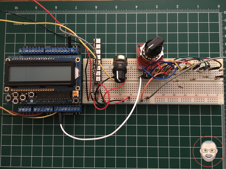
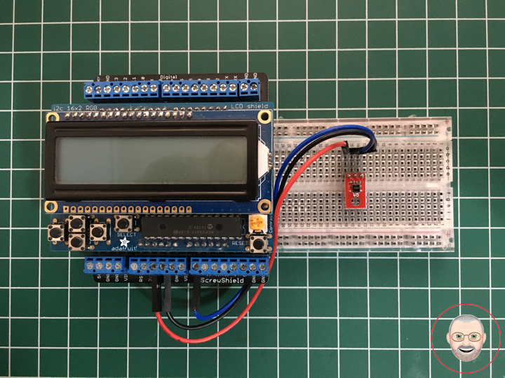
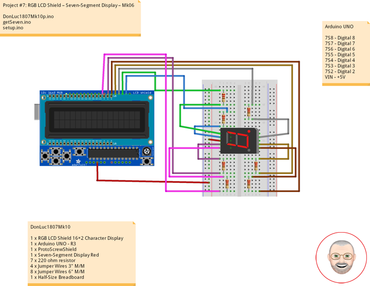
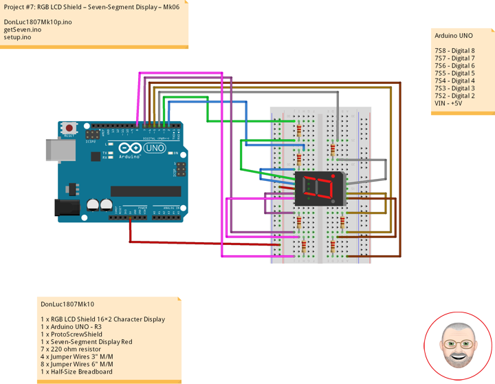
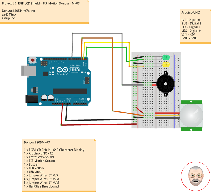
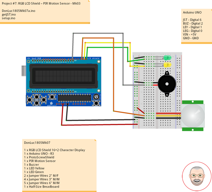
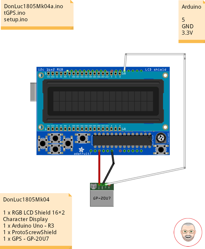
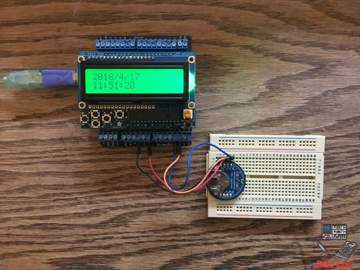
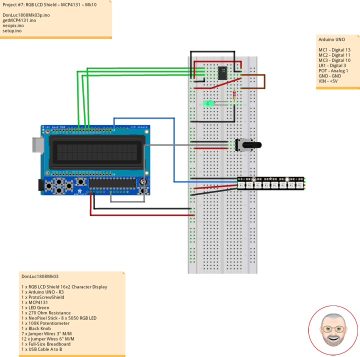
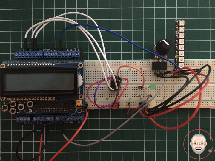
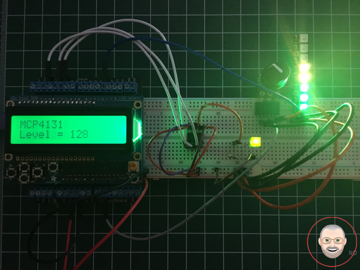
DonLuc1808Mk03
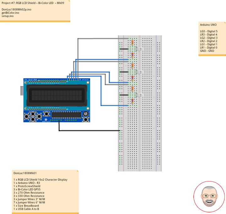
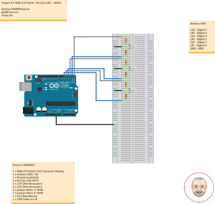
1 x RGB LCD Shield 16×2 Character Display
1 x Arduino UNO – R3
1 x ProtoScrewShield
1 x MCP4131
1 x LED Green
1 x 270 Ohm Resistance
1 x NeoPixel Stick – 8 x 5050 RGB LED
1 x 100K Potentiometer
1 x Black Knob
7 x Jumper Wires 3″ M/M
12 x Jumper Wires 6″ M/M
1 x Full-Size Breadboard
1 x USB Cable A to B
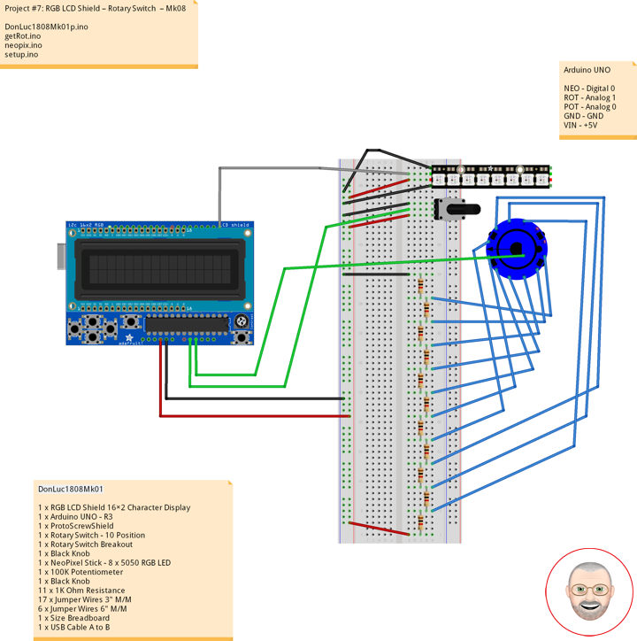
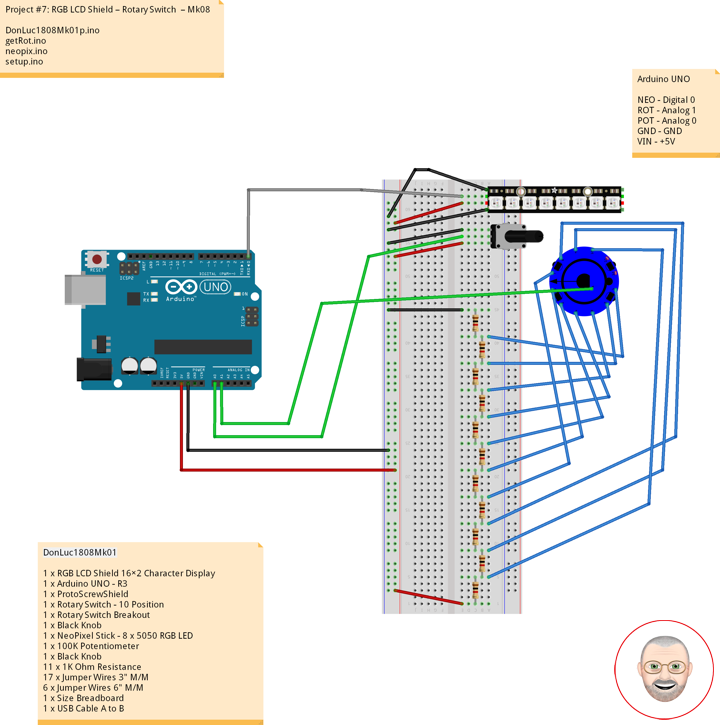
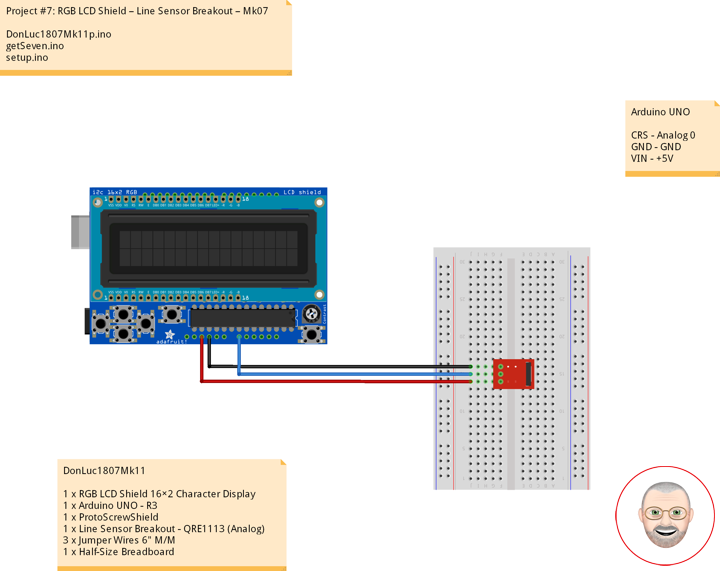
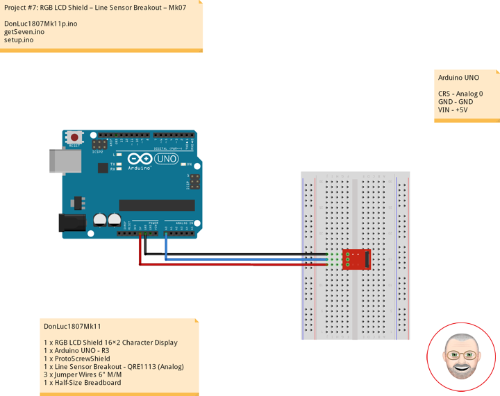
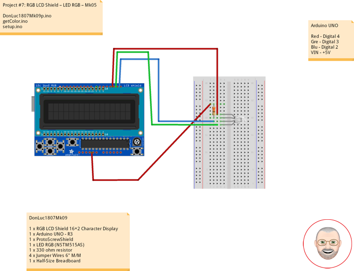
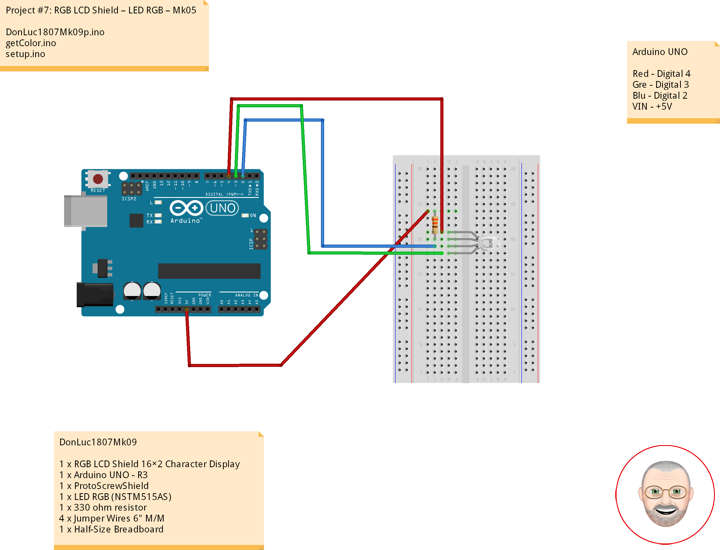
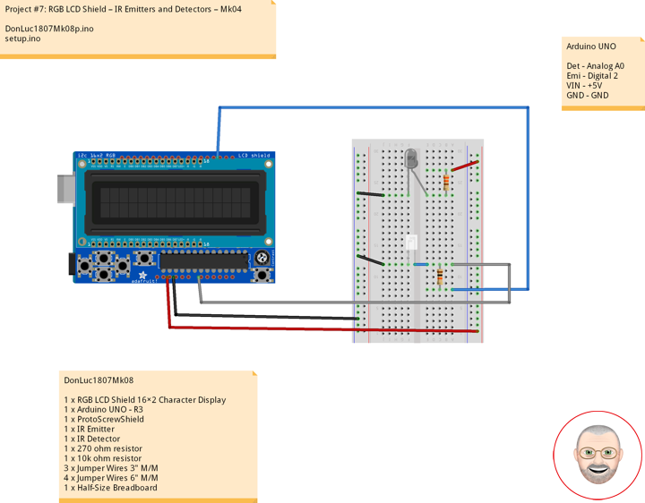
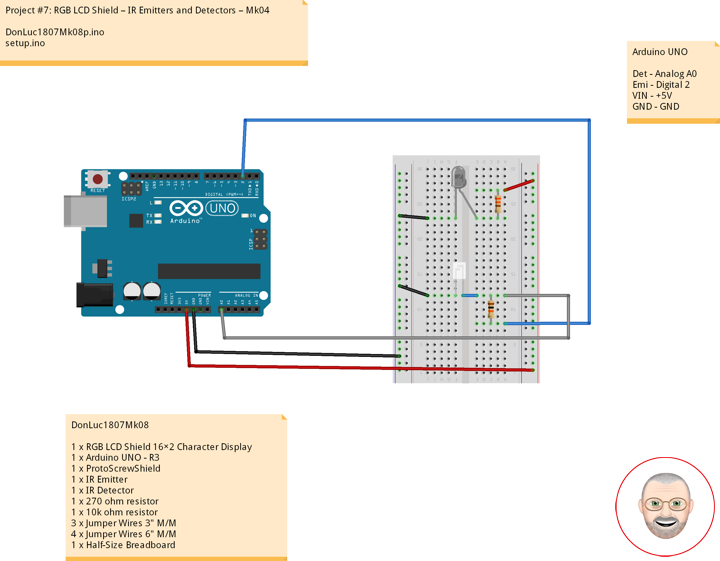
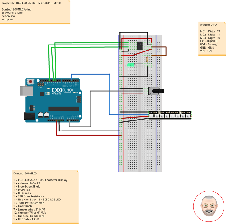
Arduino UNO
MC1 – Digital 13
MC2 – Digital 11
MC3 – Digital 10
LR1 – Digital 3
POT – Analog 1
GND – GND
VIN – +5V
DonLuc1808Mk03p.ino
// ***** Don Luc Electronics *****
// Software Version Information
// Project #7: RGB LCD Shield – MCP4131 – Mk10
// 8-03
// DonLuc1808Mk03p 8-03
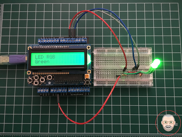
// RGB LCD Shield
// MCP4131
// Include Library Code
#include <Adafruit_MCP23017.h>
#include <Adafruit_RGBLCDShield.h>
#include <Adafruit_NeoPixel.h>
#include <SPI.h>
// RGB LCD Shield
Adafruit_RGBLCDShield RGBLCDShield = Adafruit_RGBLCDShield();
#define GREEN 0x2
// NeoPixels
#define PIN 3 // On digital pin 3
#define NUMPIXELS 8 // NeoPixels NUMPIXELS = 8
Adafruit_NeoPixel pixels = Adafruit_NeoPixel(NUMPIXELS, PIN, NEO_GRB + NEO_KHZ800);
int red = 0; // Red
int green = 0; // Green
int blue = 0; // Blue
int iNeo = 0; // Neopix
const int iBriPin = A1; // Panel Mount 1K potentiometer Brightneed
int iBri = 0; // Neopix Brightness
int iBriMin = 1023; // Brightneed minimum sensor value
int iBriMax = 0; // Brightneed maximun sensor value
int z = 0; // Value
// MCP4131
int pinCS = 10; // MCP4131
byte address = 0x00; // Address
int i = 0; // Value
void loop()
{
// MCP4131
isMCP4131();
delay(1000);
// Clear
RGBLCDShield.clear();
}
getMCP4131.ino
// MCP4131
void isMCP4131()
{
// NeoPixels
isNUMPIXELSoff(); // isNUMPIXELSoff
// Display
// Set the cursor to column 0, line 0
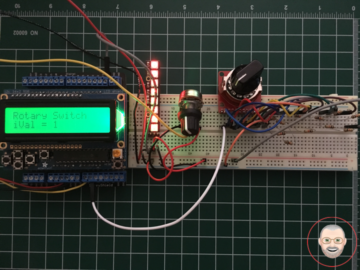
RGBLCDShield.setCursor(0,0);
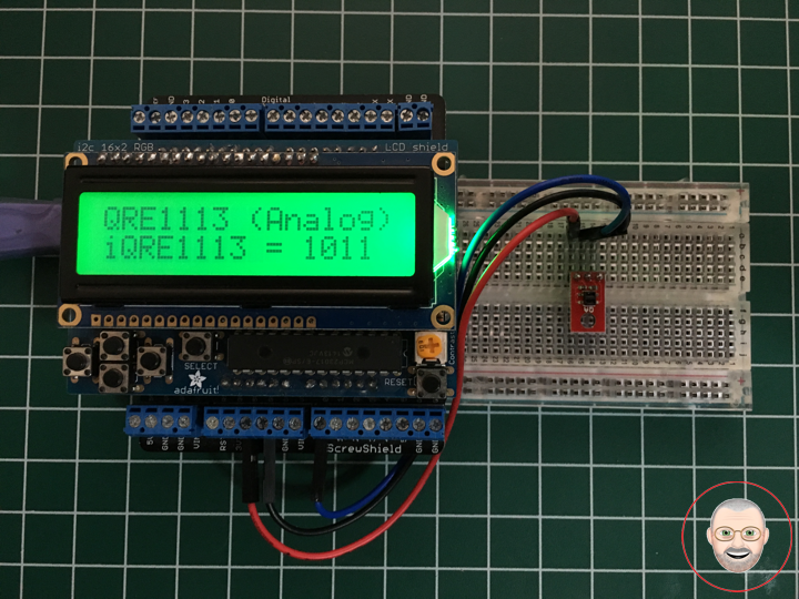
RGBLCDShield.print("MCP4131"); // MCP4131
// MCP4131
// Move the potentiometer in one direction
for ( i = 0; i <= 128; i++)
{
isNUMPIXELSoff(); // isNUMPIXELSoff
MCP4131PotWrite(i);
isNUMPIXELS(); // isNUMPIXELS
delay(100);
// Set the cursor to column 0, line 1
RGBLCDShield.setCursor(0, 1);
RGBLCDShield.print("Level = "); // MCP4131
RGBLCDShield.print(i); // MCP4131
}
delay(2000); // wait a couple seconds
// Now mover potentiometer in other directions
for ( i = 128; i >= 0; i--)
{
isNUMPIXELSoff(); // isNUMPIXELSoff
MCP4131PotWrite(i);
isNUMPIXELS(); // isNUMPIXELS
delay(100);
RGBLCDShield.setCursor(0, 1);
RGBLCDShield.print(" ");
RGBLCDShield.setCursor(0, 1);
RGBLCDShield.print("Level = "); // MCP4131
RGBLCDShield.print(i); // MCP4131
}
delay(2000);
}
// MCP4131PotWrite
int MCP4131PotWrite(int value)
{
digitalWrite(pinCS, LOW); // pinCS Off
SPI.transfer(address); // SPI Address
SPI.transfer(value); // SPI Value
digitalWrite(pinCS, HIGH); // pinCS On
}
neopix.ino
// NeoPixels
void neopix()
{

    // Brightness
    iBri = analogRead(iBriPin);

    // iBri apply the calibration to the sensor reading
    iBri = map(iBri, iBriMin, iBriMax, 0, 255);

    // iBri in case the sensor value is outside the range seen during calibration
    iBri = constrain(iBri, 0, 255);

    pixels.setBrightness( iBri );
    // Pixels.Color takes RGB values, from 0,0,0 up to 255,255,255
    pixels.setPixelColor( iNeo, pixels.Color(red,green,blue) );
    // This sends the updated pixel color to the hardware
    pixels.show();
    // Delay for a period of time (in milliseconds)
    delay(50);

}
// isNUMPIXELS
void isNUMPIXELS()
{

  // Neopix Value
  z = ( i / 16 );                             // Value

  // Neopix Value
  switch ( z ) {
    case 0:
      // NeoPixels
      // Green
      for(int y=0; y<=0; y++)
      {
         red = 0;                             // Red
         green = 255;                         // Green
         blue = 0;                            // Blue
         iNeo = y;                            // Neopix
         neopix();
      }
      break;
    case 1:
      // Green
      // NeoPixels
      for(int y=0; y<=1; y++){
         red = 0;                             // Red
         green = 255;                         // Green
         blue = 0;                            // Blue
         iNeo = y;                            // Neopix
         neopix();
      }
      break;
    case 2:
      // NeoPixels
      // Green
      for(int y=0; y<=2; y++){
         red = 0;                             // Red
         green = 255;                         // Green
         blue = 0;                            // Blue
         iNeo = y;                            // Neopix
         neopix();
      }
      break;
    case 3:
      // NeoPixels
      // Green
      for(int y=0; y<=2; y++){
         red = 0;                             // Red
         green = 255;                         // Green
         blue = 0;                            // Blue
         iNeo = y;                            // Neopix
         neopix();
      }
      // Yellow
      for(int y=3; y<=3; y++){
         red = 255;                           // Red
         green = 255;                         // Green
         blue = 0;                            // Blue
         iNeo = y;                            // Neopix
         neopix();
      }
      break;
    case 4:
      // NeoPixels
      // Green
      for(int y=0; y<=2; y++){
         red = 0;                             // Red
         green = 255;                         // Green
         blue = 0;                            // Blue
         iNeo = y;                            // Neopix
         neopix();
      }
      // Yellow
      for(int y=3; y<=4; y++){
         red = 255;                           // Red
         green = 255;                         // Green
         blue = 0;                            // Blue
         iNeo = y;                            // Neopix
         neopix();
      }
      break;
    case 5:
      // NeoPixels
      // Green
      for(int y=0; y<=2; y++){
         red = 0;                             // Red
         green = 255;                         // Green
         blue = 0;                            // Blue
         iNeo = y;                            // Neopix
         neopix();
      }
      // Yellow
      for(int y=3; y<=5; y++){
         red = 255;                           // Red
         green = 255;                         // Green
         blue = 0;                            // Blue
         iNeo = y;                            // Neopix
         neopix();
      }
      break;
    case 6:
      // NeoPixels
      // Green
      for(int y=0; y<=2; y++){
         red = 0;                             // Red
         green = 255;                         // Green
         blue = 0;                            // Blue
         iNeo = y;                            // Neopix
         neopix();
      }
      // Yellow
      for(int y=3; y<=5; y++){
         red = 255;                           // Red
         green = 255;                         // Green
         blue = 0;                            // Blue
         iNeo = y;                            // Neopix
         neopix();
      }
      // Red
      for(int y=6; y<=6; y++){
         red = 255;                           // Red
         green = 0;                           // Green
         blue = 0;                            // Blue
         iNeo = y;                            // Neopix
         neopix();
      }
      break;
    case 7:
      // NeoPixels
      // Green
      for(int y=0; y<=2; y++){
         red = 0;                             // Red
         green = 255;                         // Green
         blue = 0;                            // Blue
         iNeo = y;                            // Neopix
         neopix();
      }
      // Yellow
      for(int y=3; y<=5; y++){
         red = 255;                           // Red
         green = 255;                         // Green
         blue = 0;                            // Blue
         iNeo = y;                            // Neopix
         neopix();
      }
      // Red
      for(int y=6; y<=7; y++){
         red = 255;                           // Red
         green = 0;                           // Green
         blue = 0;                            // Blue
         iNeo = y;                            // Neopix
         neopix();
      }
      break;
    case 8:
      // NeoPixels
      // Green
      for(int y=0; y<=2; y++){
         red = 0;                             // Red
         green = 255;                         // Green
         blue = 0;                            // Blue
         iNeo = y;                            // Neopix
         neopix();
      }
      // Yellow
      for(int y=3; y<=5; y++){
         red = 255;                           // Red
         green = 255;                         // Green
         blue = 0;                            // Blue
         iNeo = y;                            // Neopix
         neopix();
      }
      // Red
      for(int y=6; y<=7; y++){
         red = 255;                           // Red
         green = 0;                           // Green
         blue = 0;                            // Blue
         iNeo = y;                            // Neopix
         neopix();
      }
      break;
  }

}
// isNUMPIXELSoff
void isNUMPIXELSoff()
{

   // Black
   // NeoPixels
   for(int y=0; y < NUMPIXELS; y++)
   {
      red = 0;                                 // Red
      green = 0;                               // Green
      blue = 0;                                // Blue
      iNeo = y;                                // Neopix
      neopix();
   }

}
setup.ino
// Setup
void setup()
{

  // set up the LCD's number of columns and rows:
  RGBLCDShield.begin(16, 2);
  RGBLCDShield.setBacklight(GREEN);

  // Display
  // Set the cursor to column 0, line 0
  RGBLCDShield.setCursor(0,0);
  RGBLCDShield.print("Don Luc");           // Don luc
  // Set the cursor to column 0, line 1
  RGBLCDShield.setCursor(0, 1);
  RGBLCDShield.print("MCP4131");           // MCP4131
  delay(5000);

  // Clear
  RGBLCDShield.clear();

  // NeoPixels
  pixels.begin();                          // This initializes the NeoPixel library
  // NeoPixels
  isNUMPIXELSoff();                        // isNUMPIXELSoff

  // MCP4131
  pinMode(pinCS, OUTPUT);                  // MCP4131 OUTPUT

  SPI.begin();                             // SPI

}
Don Luc