——
#donluc #meditation #glassesledmeditation #musicshield #neopixels #arduino #sparkfun #project #programming #electronics #microcontrollers #consultant #zoom #patreon #videoblog
——
——
——
——
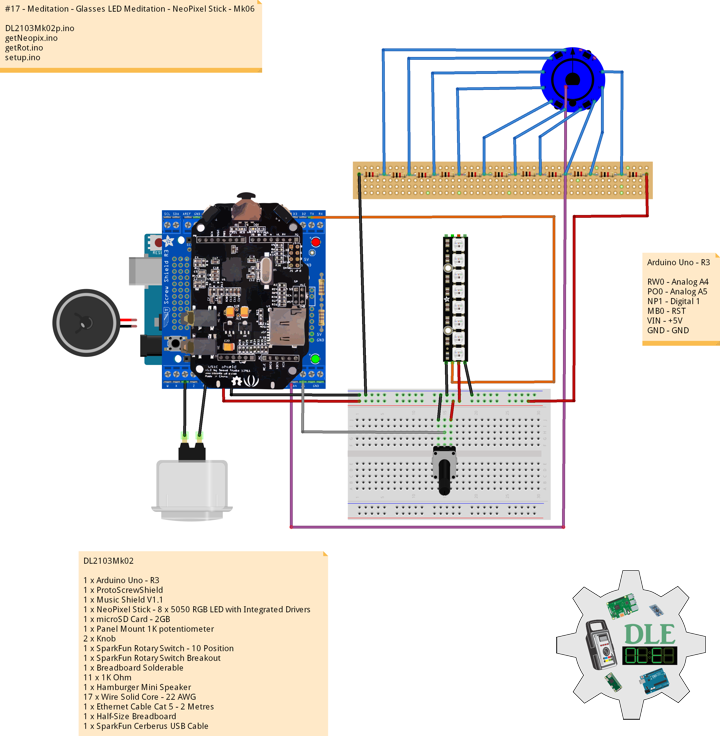
NeoPixel Stick – 8 x 5050 RGB LED with Integrated Drivers
Make your own little LED strip arrangement with this stick of NeoPixel LEDs. We crammed 8 of the tiny 5050 (5mm x 5mm) smart RGB LEDs onto a PCB with mounting holes and a chainable design. Use only one microcontroller pin to control as many as you can chain together! Each LED is addressable as the driver chip is inside the LED. Each one has ~18mA constant current drive so the color will be very consistent even if the voltage varies, and no external choke resistors are required making the design slim. Power the whole thing with 5VDC (4-7V works).
The LEDs are ‘chainable’ by connecting the output of one stick into the input of another. There is a single data line with a very timing-specific protocol. Since the protocol is very sensitive to timing, it requires a real-time microconroller such as an AVR, Arduino, PIC, mbed, etc. It cannot be used with a Linux-based microcomputer or interpreted microcontroller such as the netduino or Basic Stamp. Our wonderfully-written Neopixel library for Arduino supports these pixels. As it requires hand-tuned assembly it is only for AVR cores but others may have ported this chip driver code so please google around. An 8MHz or faster processor is required.
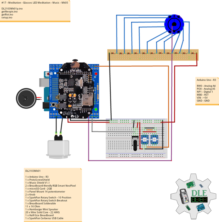
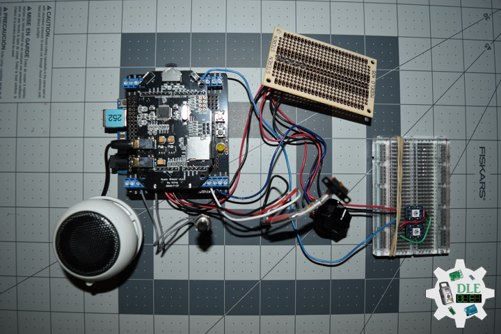
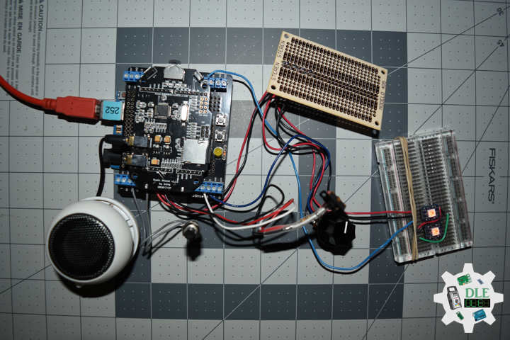
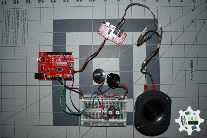
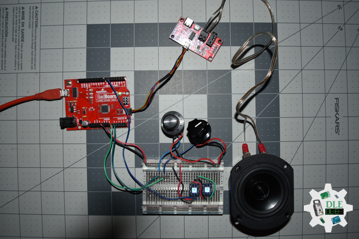
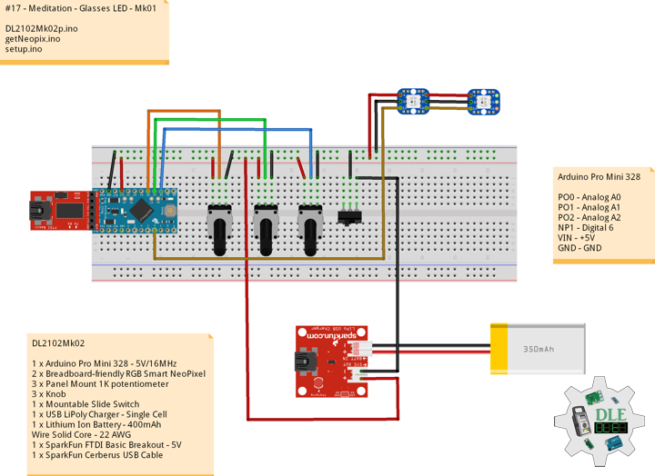
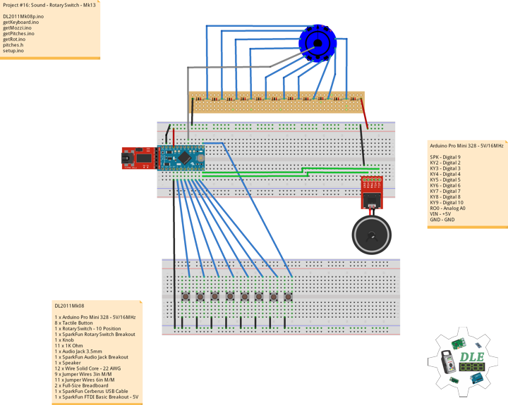
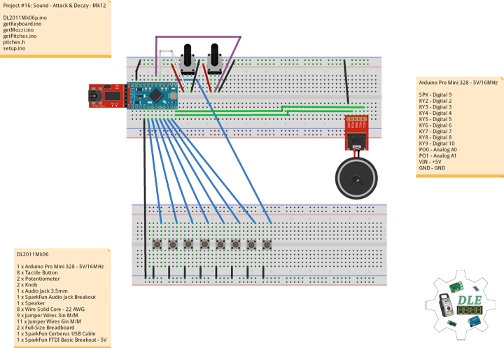
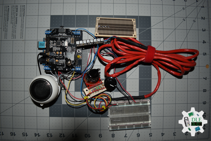
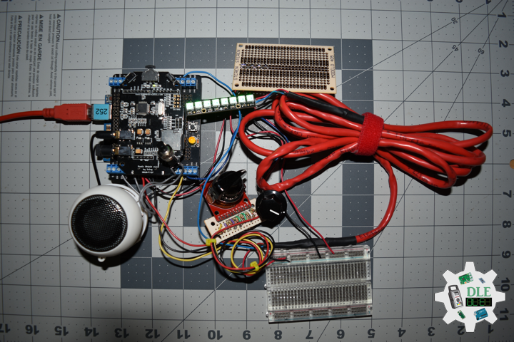
DL2103Mk02
1 x Arduino Uno – R3
1 x ProtoScrewShield
1 x Music Shield V1.1
1 x NeoPixel Stick – 8 x 5050 RGB LED with Integrated Drivers
1 x microSD Card – 2GB
1 x Panel Mount 1K potentiometer
2 x Knob
1 x SparkFun Rotary Switch – 10 Position
1 x SparkFun Rotary Switch Breakout
1 x Breadboard Solderable
11 x 1K Ohm
1 x Hamburger Mini Speaker
17 x Wire Solid Core – 22 AWG
1 x Ethernet Cable Cat 5 – 2 Metres
1 x Half-Size Breadboard
1 x SparkFun Cerberus USB Cable
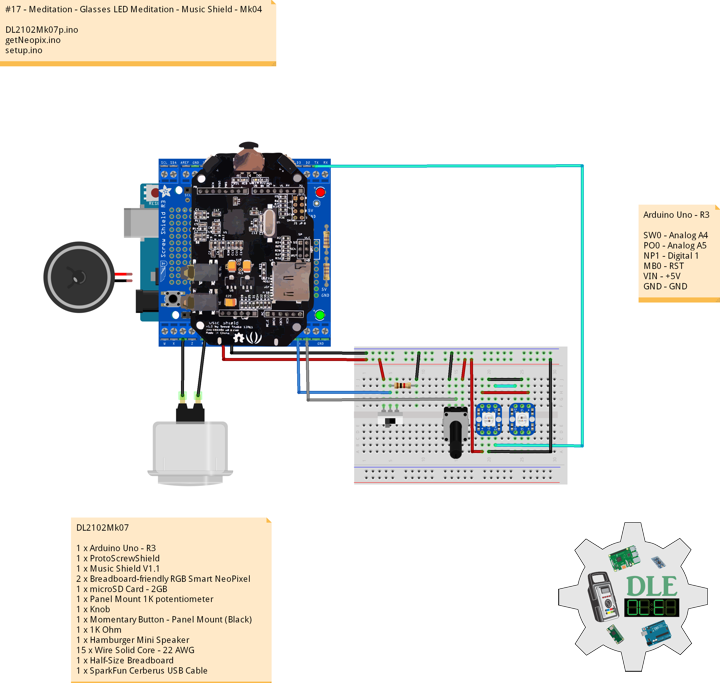
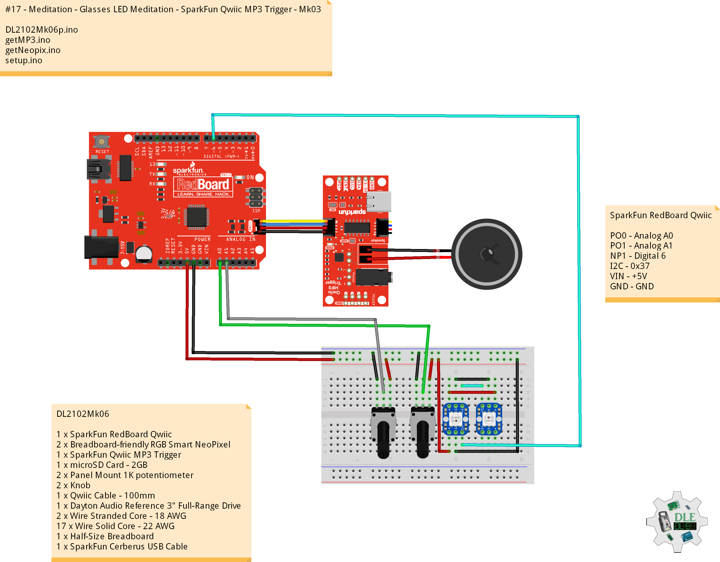
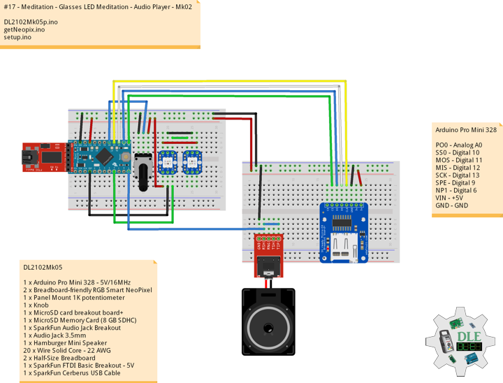
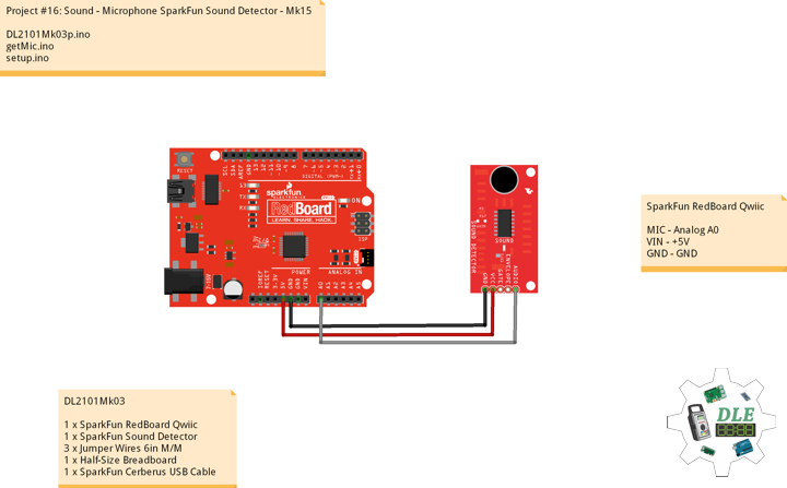
Arduino Uno – R3
RW0 – Analog A4
PO0 – Analog A5
NP1 – Digital 1
MB0 – RST
VIN – +5V
GND – GND
DL2103Mk02p.ino
// ***** Don Luc Electronics © *****
// Software Version Information
// #17 - Meditation - Glasses LED Meditation - NeoPixel Stick - Mk06
// 03-02
// DL2103Mk02p.ino 17-06
// DL2103Mk02
// 1 x Arduino Uno - R3
// 1 x ProtoScrewShield
// 1 x Music Shield V1.1
// 1 x NeoPixel Stick - 8 x 5050 RGB LED with Integrated Drivers
// 1 x microSD Card - 2GB
// 1 x Panel Mount 1K potentiometer
// 11 x Knob
// 1 x SparkFun Rotary Switch - 10 Position
// 1 x SparkFun Rotary Switch Breakout
// 1 x Breadboard Solderable
// 11 x 1K Ohm
// 1 x Hamburger Mini Speaker
// 17 x Wire Solid Core - 22 AWG
// 1 x Ethernet Cable Cat 5 - 2 Metres
// 1 x Half-Size Breadboard
// 1 x SparkFun Cerberus USB Cable

// Include the Library Code
// NeoPixel
#include <Adafruit_NeoPixel.h>
// Fat 16
#include <Fat16.h>
#include <Fat16Util.h>
// New SPI
#include <NewSPI.h>
// Arduino
#include <arduino.h>
// Music Player
#include "pins_config.h"
#include "vs10xx.h"
#include "newSDLib.h"
#include "MusicPlayer.h"

// NeoPixels
#define PIN 1
// How many NeoPixels are attached to the Arduino
#define NUMPIXELS 8
Adafruit_NeoPixel pixels = Adafruit_NeoPixel(NUMPIXELS, PIN, NEO_GRB + NEO_KHZ800);
// Color
// Red
int red = 0;
// Green
int green = 0;
// Blue
int blue = 0;
// Panel Mount 1K potentiometer
// Brighten
int BrightenValue = 0;
// Color
const int iSensorColor = A5;
int y = 0;
int ColorVal = 0;

// Rotary Switch - 10 Position
// Number 1 => 10
int iRotNum = A4;
// iRotVal - Value
int iRotVal = 0;
// Number
int z = 0;
int x = 0;

// Music Player
MusicPlayer myplayer;

// Software Version Information
String sver = "17-06";

void loop() {

  // Rotary Switch
  isRot();

}
getNeopix.ino
// Neopix
void isNeopix() {

  for(int i=0; i<NUMPIXELS; i++){

    // Neopix
    // BrightenValue = 40
    BrightenValue = 40;
    pixels.setBrightness( BrightenValue );

    // The pixels.Color takes RGB values, from 0,0,0 up to 255,255,255
    pixels.setPixelColor(i, pixels.Color(red,green,blue));

    // This sends the updated pixel color to the hardware
    pixels.show();

  }

}
// Range Color
void isRangeColor() {

  // Range Color
  ColorVal = analogRead( iSensorColor );
  y = (ColorVal / 127);

  switch ( y ) {
    case  0:
      // Blue
      red = 0;
      green = 102;
      blue = 204;
      isNeopix();
      break;
    case 1:
      // Yellow
      red = 255;
      green = 255;
      blue = 0;
      isNeopix();
      break;
    case 2:
      // Pink
      red = 255;
      green = 153;
      blue = 203;
      isNeopix();
      break;
    case 3:
      // White
      red = 255;
      green = 255;
      blue = 255;
      isNeopix();
      break;
    case 4:
      // Green
      red = 0;
      green = 255;
      blue = 0;
      isNeopix();
      break;
    case 5:
      // Orange
      red = 255;
      green = 102;
      blue = 0;
      isNeopix();
      break;
    case 6:
      // Violet
      red = 204;
      green = 102;
      blue = 204;
      isNeopix();
      break;
    case 7:
      // Red
      red = 255;
      green = 0;
      blue = 0;
      isNeopix();
      break;
  }

}
getRot.ino
// Rotary Switch
// isRot - iRotVal - Value
void isRot() {

  // Rotary Switch
  z = analogRead( iRotNum );
  x = map(z, 0, 4095, 0, 9);
  iRotVal = map(z, 0, 1023, 0, 10);

  // Range Value
  switch ( iRotVal ) {
    case 0:

      // Range Color
      isRangeColor();

      break;
    case 1:

      // Music
      // Add To Playlist
      // 3:18
      myplayer.addToPlaylist("DLEMk001.mp3");
      // 2:47
      myplayer.addToPlaylist("DLEMk002.mp3");
      // 4.34
      myplayer.addToPlaylist("DLEMk003.mp3");
      // There are two songs in the playlist
      // 10:37
      myplayer.playList();
      while(1);

      break;
    case 2:

      // Music
      // Add To Playlist
      // 22:53
      myplayer.addToPlaylist("DLEMk004.mp3");
      // There are two songs in the playlist
      // 22:53
      myplayer.playList();
      while(1);

      break;
    case 3:

      // Music
      // Add To Playlist
      // 4:18
      myplayer.addToPlaylist("DLEMk005.mp3");
      // 4:20
      myplayer.addToPlaylist("DLEMk006.mp3");
      // There are two songs in the playlist
      // 8:38
      myplayer.playList();
      while(1);

      break;
    case 4:

      // Music
      // Add To Playlist
      // 9:14
      myplayer.addToPlaylist("DLEMk007.mp3");
      // 7:52
      myplayer.addToPlaylist("DLEMk008.mp3");
      // There are two songs in the playlist
      // 17:07
      myplayer.playList();
      while(1);

      break;
    case 5:

      // Music
      // Add To Playlist
      // 4:37
      myplayer.addToPlaylist("DLEMk009.mp3");
      // There are two songs in the playlist
      // 4:37
      myplayer.playList();
      while(1);

      break;
    case 6:

      // Music
      // Add To Playlist
      // 8:40
      myplayer.addToPlaylist("DLEMk010.mp3");
      // 8:40
      myplayer.playList();
      while(1);

      break;
    case 7:

      // Music
      // Add To Playlist
      // 1:31
      myplayer.addToPlaylist("DLEMk011.mp3");
      // 3:29
      myplayer.addToPlaylist("DLEMk012.mp3");
      // There are two songs in the playlist
      // 5:00
      myplayer.playList();
      while(1);

      break;
    case 8:

      // Music
      // Add To Playlist
      // 6:14
      myplayer.addToPlaylist("DLEMk013.mp3");
      // 5:17
      myplayer.addToPlaylist("DLEMk014.mp3");
      // There are two songs in the playlist
      // 11:31
      myplayer.playList();
      while(1);

      break;
    case 9:

      // Music
      // Add To Playlist
      // 6:30
      myplayer.addToPlaylist("DLEMk015.mp3");
      // 3:00
      myplayer.addToPlaylist("DLEMk016.mp3");
      // There are two songs in the playlist
      // 9:30
      myplayer.playList();
      while(1);

      break;
  }

}
setup.ino
// Setup
void setup() {

   // This initializes the NeoPixel library
   pixels.begin();
   delay(50);

   // Range Color
   isRangeColor();

   // Music Player
   // Will initialize the hardware and set default mode to be normal
   myplayer.begin();

}
Music 01 – 10m 37s
DLEMk001.mp3
DLEMk002.mp3
DLEMk003.mp3
Music 02 – 22m 53s
DLEMk004.mp3
Music 03 – 8m 38s
DLEMk005.mp3
DLEMk006.mp3
Music 04 – 17m 07s
DLEMk007.mp3
DLEMk008.mp3
Music 05 – 4m 37s
DLEMk009.mp3
Music 06 – 8m 40s
DLEMk010.mp3
Music 07 – 5m 00s
DLEMk011.mp3
DLEMk012.mp3
Music 08 – 11m 31s
DLEMk013.mp3
DLEMk014.mp3
Music 09 – 9m 30s
DLEMk015.mp3
DLEMk016.mp3
People can contact us: https://www.donluc.com/?page_id=1927
Technology Experience
- Single-Board Microcontrollers (PIC, Arduino, Raspberry Pi,Espressif, etc…)
- Robotics
- Research & Development (R & D)
- Desktop Applications (Windows, OSX, Linux, Multi-OS, Multi-Tier, etc…)
- Mobile Applications (Android, iOS, Blackberry, Windows Mobile, Windows CE, etc…)
- Web Applications (LAMP, Scripting, Java, ASP, ASP.NET, RoR, Wakanda, etc…)
- Social Media Programming & Integration (Facebook, Twitter, YouTube, Pinterest, etc…)
- Content Management Systems (WordPress, Drupal, Joomla, Moodle, etc…)
- Bulletin Boards (phpBB, SMF, Vanilla, jobberBase, etc…)
- eCommerce (WooCommerce, OSCommerce, ZenCart, PayPal Shopping Cart, etc…)
Instructor
- PIC Microcontrollers
- Arduino
- Raspberry Pi
- Espressif
- Robotics
- DOS, Windows, OSX, Linux, iOS, Android, Multi-OS
- Linux-Apache-PHP-MySQL
Follow Us
J. Luc Paquin – Curriculum Vitae
https://www.donluc.com/DLE/LucPaquinCVEngMk2021a.pdf
Web: https://www.donluc.com/
Web: http://www.jlpconsultants.com/
Web: https://www.donluc.com/DLE/
Web: https://www.donluc.com/DLHackster/
Web: https://www.hackster.io/neosteam-labs
Web: https://zoom.us/
Patreon: https://www.patreon.com/DonLucElectronics
Facebook: https://www.facebook.com/neosteam.labs.9/
YouTube: https://www.youtube.com/channel/UC5eRjrGn1CqkkGfZy0jxEdA
Twitter: https://twitter.com/labs_steam
Pinterest: https://www.pinterest.com/NeoSteamLabs/
Instagram: https://www.instagram.com/neosteamlabs/
Don Luc