——
#donluc #meditation #glassesledmeditation #musicshield #neopixels #arduino #sparkfun #project #programming #electronics #microcontrollers #consultant #zoom #patreon #videoblog
——
——
——
——
Meditation or Aesthetics or Ambient of Music
Aesthetics of music is a branch of philosophy that deals with the nature of art, beauty and taste in music, and with the creation or appreciation of beauty in music. In the pre-modern tradition, the aesthetics of music or musical aesthetics explored the mathematical and cosmological dimensions of rhythmic and harmonic organization.
As an early 20th-century French composer, Erik Satie used such Dadaist-inspired explorations to create an early form of ambient/background music that he labeled “furniture music”. This he described as being the sort of music that could be played during a dinner to create a background atmosphere for that activity, rather than serving as the focus of attention.
I think of it as melodious, softening the noises of the knives and forks at dinner, not dominating them, not imposing itself. It would fill up those heavy silences that sometime fall between friends dining together. It would spare them the trouble of paying attention to their own banal remarks. And at the same time it would neutralize the street noises which so indiscreetly enter into the play of conversation. To make such music would be to respond to a need.
Background music for meditation should be calm, relaxing, and to evoke a warm feeling that allows viewers to feel safe and comfortable. Moreover, meditating music should quiet the inner voice, allowing the viewer to stay in the present moment and focus on immersing in meditation.
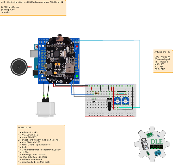
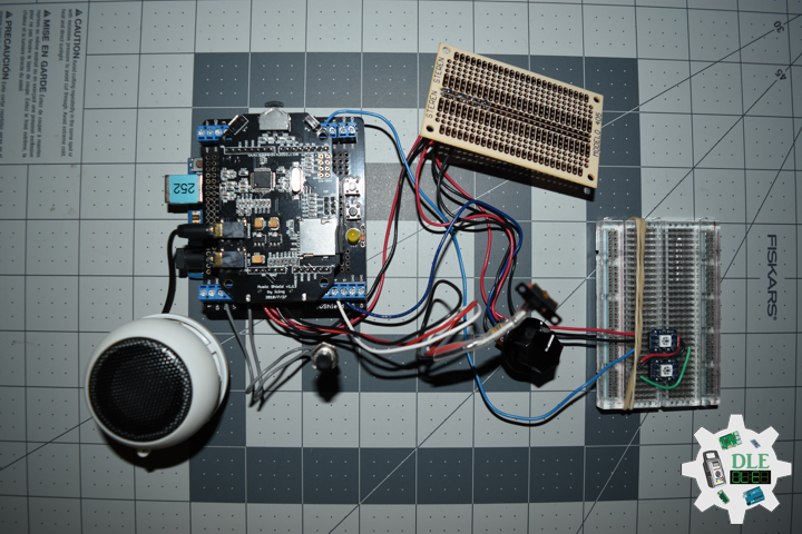
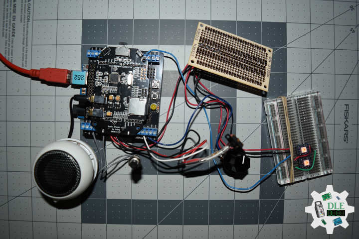
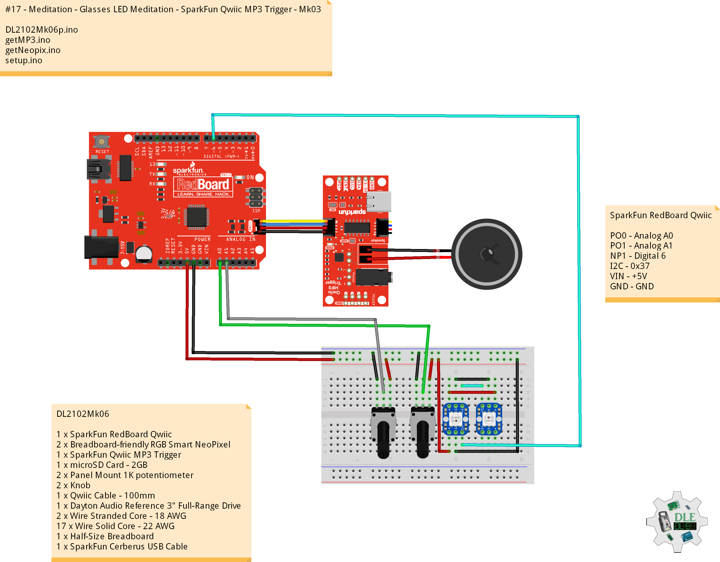
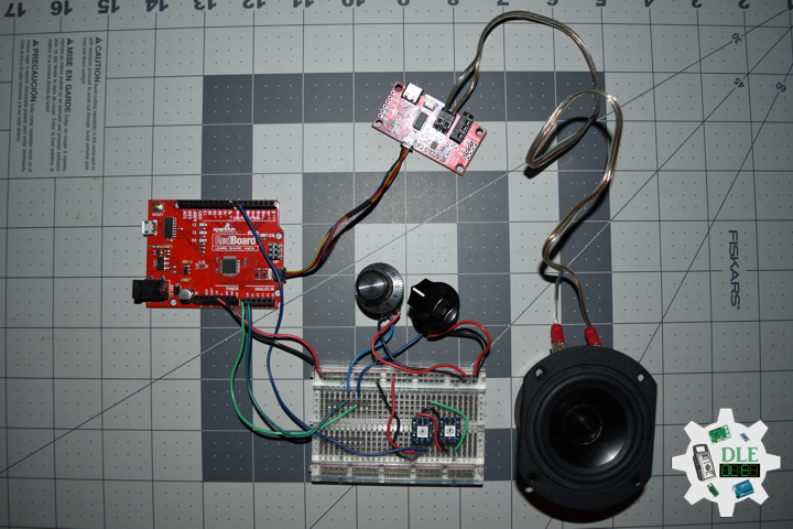
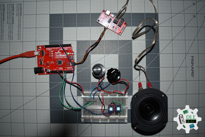
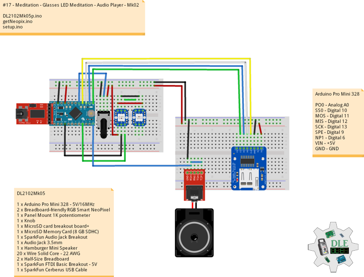
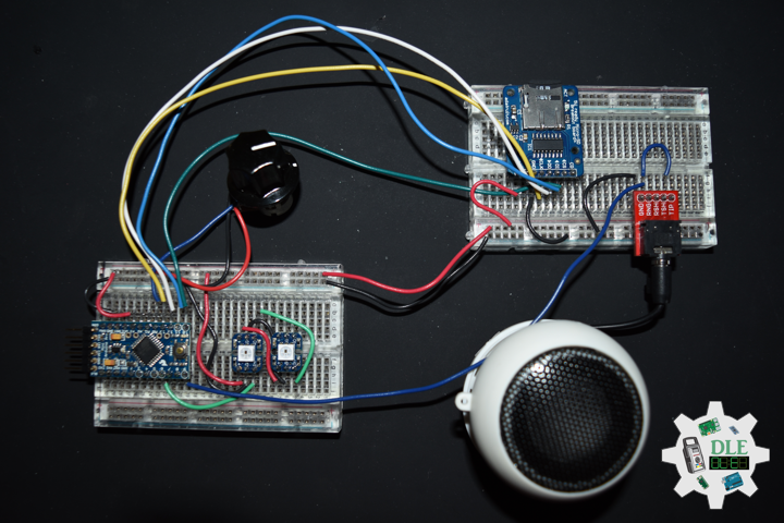
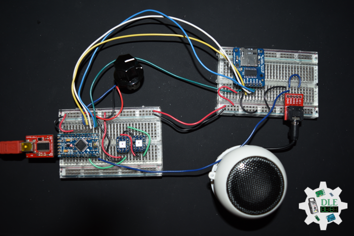
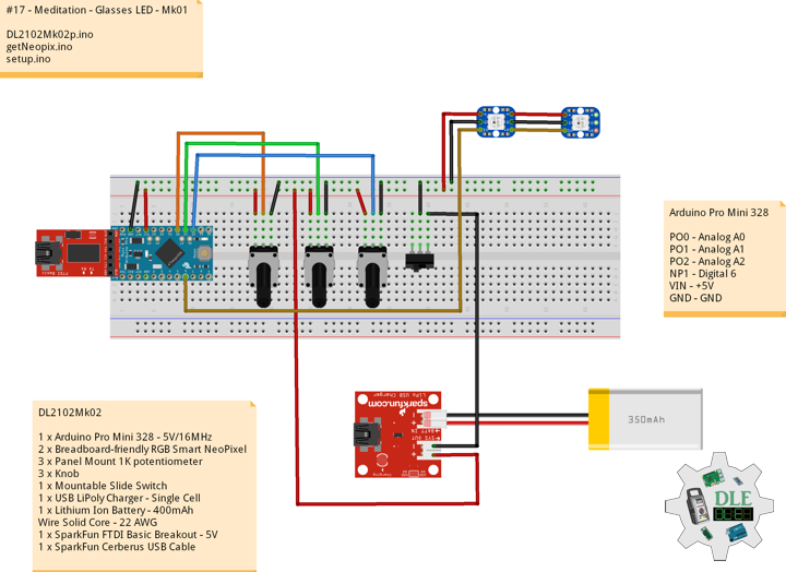
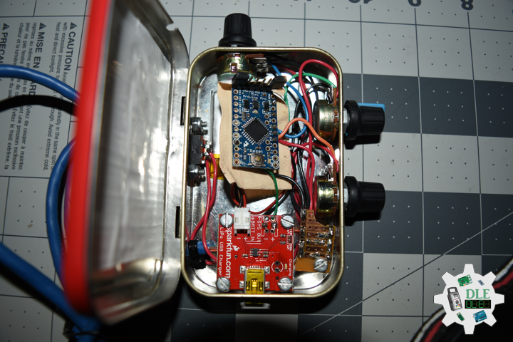
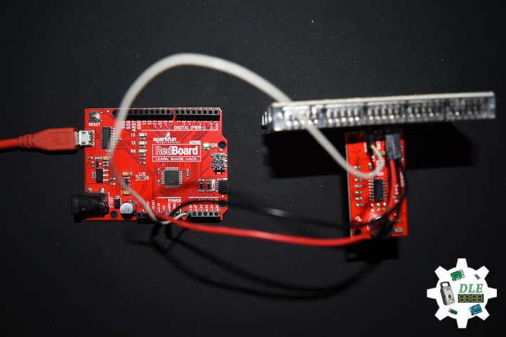
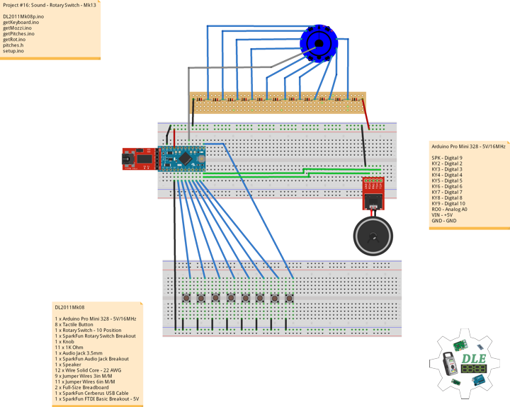
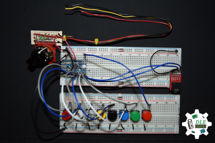
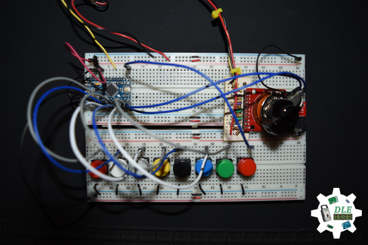
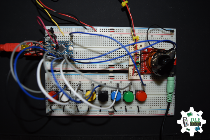
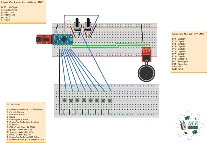
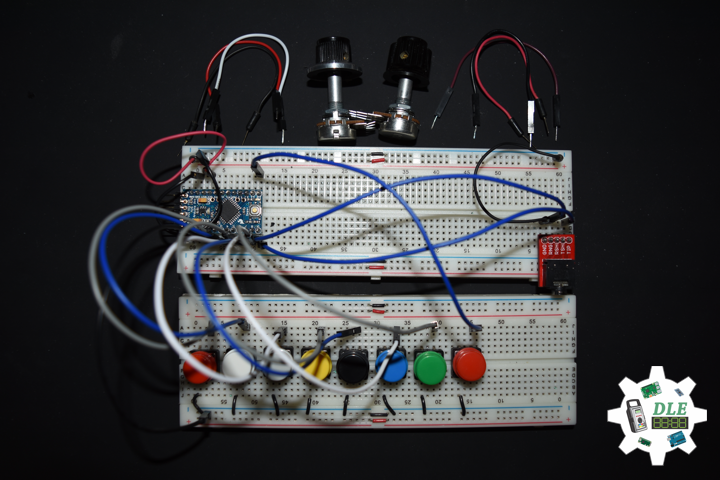
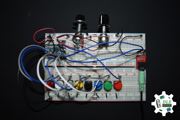
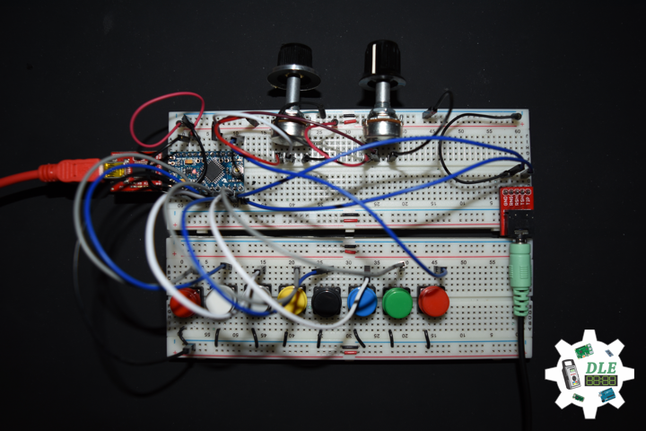
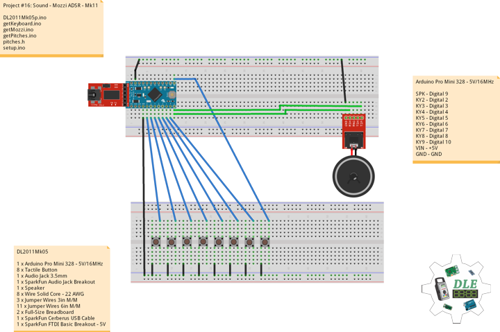
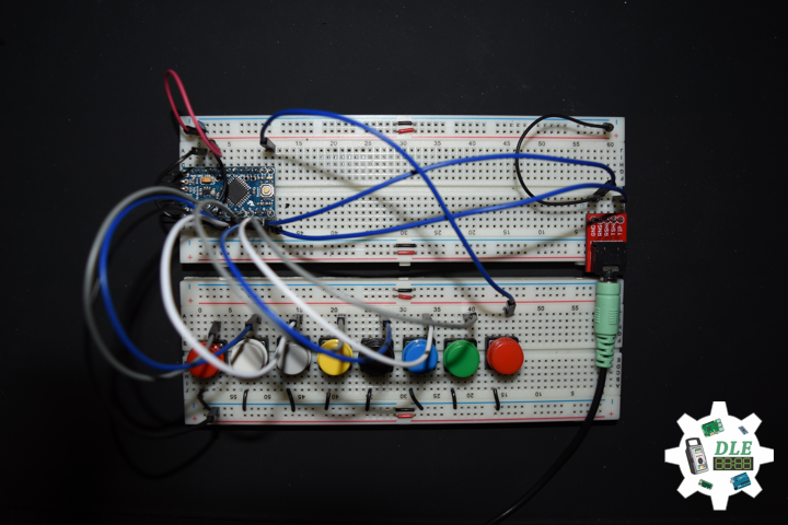
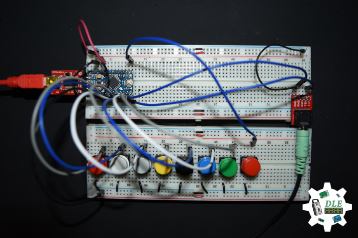
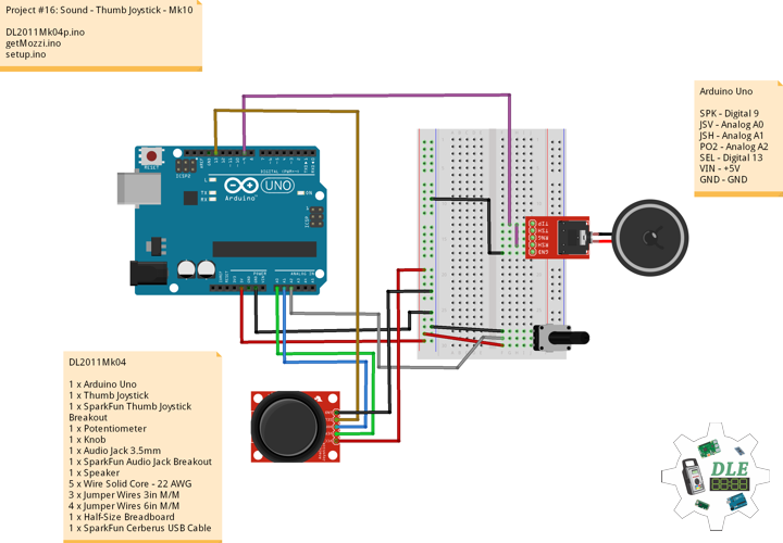
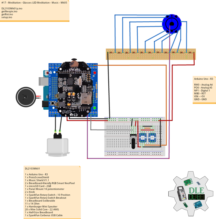
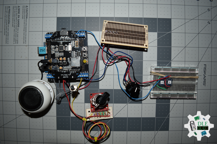
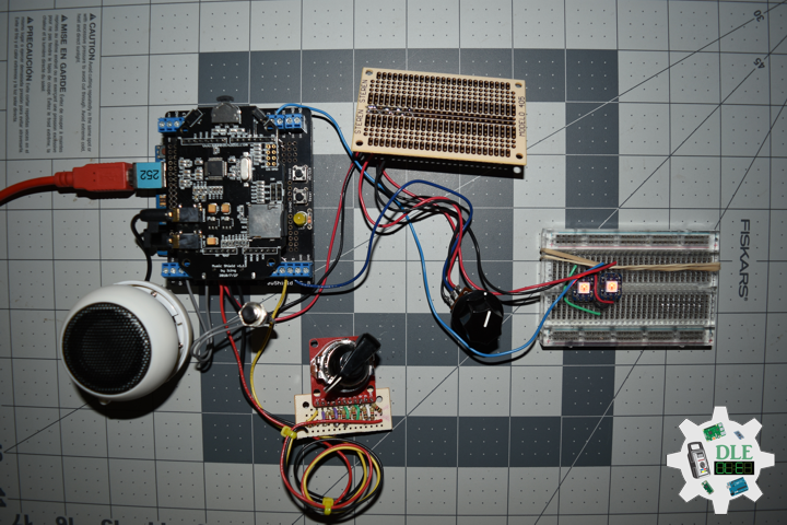
DL2103Mk01
1 x Arduino Uno – R3
1 x ProtoScrewShield
1 x Music Shield V1.1
2 x Breadboard-friendly RGB Smart NeoPixel
1 x microSD Card – 2GB
1 x Panel Mount 1K potentiometer
2 x Knob
1 x SparkFun Rotary Switch – 10 Position
1 x SparkFun Rotary Switch Breakout
1 x Breadboard Solderable
11 x 1K Ohm
1 x Hamburger Mini Speaker
20 x Wire Solid Core – 22 AWG
1 x Half-Size Breadboard
1 x SparkFun Cerberus USB Cable
Arduino Uno – R3
RW0 – Analog A4
PO0 – Analog A5
NP1 – Digital 1
MB0 – RST
VIN – +5V
GND – GND
DL2103Mk01p.ino
// ***** Don Luc Electronics © *****
// Software Version Information
// #17 - Meditation - Glasses LED Meditation - Music - Mk05
// 03-01
// DL2103Mk01p.ino 17-05
// DL2103Mk01
// 1 x Arduino Uno - R3
// 1 x ProtoScrewShield
// 1 x Music Shield V1.1
// 2 x Breadboard-friendly RGB Smart NeoPixel
// 1 x microSD Card - 2GB
// 1 x Panel Mount 1K potentiometer
// 11 x Knob
// 1 x SparkFun Rotary Switch - 10 Position
// 1 x SparkFun Rotary Switch Breakout
// 1 x Breadboard Solderable
// 11 x 1K Ohm
// 1 x Hamburger Mini Speaker
// 20 x Wire Solid Core - 22 AWG
// 1 x Half-Size Breadboard
// 1 x SparkFun Cerberus USB Cable

// Include the Library Code
// NeoPixel
#include <Adafruit_NeoPixel.h>
// Fat 16
#include <Fat16.h>
#include <Fat16Util.h>
// New SPI
#include <NewSPI.h>
// Arduino
#include <arduino.h>
// Music Player
#include "pins_config.h"
#include "vs10xx.h"
#include "newSDLib.h"
#include "MusicPlayer.h"

// NeoPixels
#define PIN 1
// How many NeoPixels are attached to the Arduino
#define NUMPIXELS 2
Adafruit_NeoPixel pixels = Adafruit_NeoPixel(NUMPIXELS, PIN, NEO_GRB + NEO_KHZ800);
// Color
// Red
int red = 0;
// Green
int green = 0;
// Blue
int blue = 0;
// Panel Mount 1K potentiometer
// Brighten
int BrightenValue = 0;
// Color
const int iSensorColor = A5;
int y = 0;
int ColorVal = 0;

// Rotary Switch - 10 Position
// Number 1 => 10
int iRotNum = A4;
// iRotVal - Value
int iRotVal = 0;
// Number
int z = 0;
int x = 0;

// Music Player
MusicPlayer myplayer;

// Software Version Information
String sver = "17-05";

void loop() {

  // Rotary Switch
  isRot();

}
getNeopix.ino
// Neopix
void isNeopix() {

  for(int i=0; i<NUMPIXELS; i++){

    // Neopix
    // BrightenValue = 40
    BrightenValue = 40;
    pixels.setBrightness( BrightenValue );

    // The pixels.Color takes RGB values, from 0,0,0 up to 255,255,255
    pixels.setPixelColor(i, pixels.Color(red,green,blue));

    // This sends the updated pixel color to the hardware
    pixels.show();

  }

}
// Range Color
void isRangeColor() {

  // Range Color
  ColorVal = analogRead( iSensorColor );
  y = (ColorVal / 127);

  switch ( y ) {
    case  0:
      // Blue
      red = 0;
      green = 102;
      blue = 204;
      isNeopix();
      break;
    case 1:
      // Yellow
      red = 255;
      green = 255;
      blue = 0;
      isNeopix();
      break;
    case 2:
      // Pink
      red = 255;
      green = 153;
      blue = 203;
      isNeopix();
      break;
    case 3:
      // White
      red = 255;
      green = 255;
      blue = 255;
      isNeopix();
      break;
    case 4:
      // Green
      red = 0;
      green = 255;
      blue = 0;
      isNeopix();
      break;
    case 5:
      // Orange
      red = 255;
      green = 102;
      blue = 0;
      isNeopix();
      break;
    case 6:
      // Violet
      red = 204;
      green = 102;
      blue = 204;
      isNeopix();
      break;
    case 7:
      // Red
      red = 255;
      green = 0;
      blue = 0;
      isNeopix();
      break;
  }

}
getRot.ino
// Rotary Switch
// isRot - iRotVal - Value
void isRot() {

  // Rotary Switch
  z = analogRead( iRotNum );
  x = map(z, 0, 4095, 0, 9);
  iRotVal = map(z, 0, 1023, 0, 10);

  // Range Value
  switch ( iRotVal ) {
    case 0:

      // Range Color
      isRangeColor();

      break;
    case 1:

      // Music
      // Add To Playlist
      // 3:18
      myplayer.addToPlaylist("DLEMk001.mp3");
      // 2:47
      myplayer.addToPlaylist("DLEMk002.mp3");
      // 4.34
      myplayer.addToPlaylist("DLEMk003.mp3");
      // There are two songs in the playlist
      // 10:37
      myplayer.playList();
      while(1);

      break;
    case 2:

      // Music
      // Add To Playlist
      // 22:53
      myplayer.addToPlaylist("DLEMk004.mp3");
      // There are two songs in the playlist
      // 22:53
      myplayer.playList();
      while(1);

      break;
    case 3:

      // Music
      // Add To Playlist
      // 4:18
      myplayer.addToPlaylist("DLEMk005.mp3");
      // 4:20
      myplayer.addToPlaylist("DLEMk006.mp3");
      // There are two songs in the playlist
      // 8:38
      myplayer.playList();
      while(1);

      break;
    case 4:

      // Music
      // Add To Playlist
      // 9:14
      myplayer.addToPlaylist("DLEMk007.mp3");
      // 7:52
      myplayer.addToPlaylist("DLEMk008.mp3");
      // There are two songs in the playlist
      // 17:07
      myplayer.playList();
      while(1);

      break;
    case 5:

      // Music
      // Add To Playlist
      // 4:37
      myplayer.addToPlaylist("DLEMk009.mp3");
      // There are two songs in the playlist
      // 4:37
      myplayer.playList();
      while(1);

      break;
    case 6:

      // Music
      // Add To Playlist
      // 8:40
      myplayer.addToPlaylist("DLEMk010.mp3");
      // 8:40
      myplayer.playList();
      while(1);

      break;
    case 7:

      // Music
      // Add To Playlist
      // 1:31
      myplayer.addToPlaylist("DLEMk011.mp3");
      // 3:29
      myplayer.addToPlaylist("DLEMk012.mp3");
      // There are two songs in the playlist
      // 5:00
      myplayer.playList();
      while(1);

      break;
    case 8:

      // Music
      // Add To Playlist
      // 6:14
      myplayer.addToPlaylist("DLEMk013.mp3");
      // 5:17
      myplayer.addToPlaylist("DLEMk014.mp3");
      // There are two songs in the playlist
      // 11:31
      myplayer.playList();
      while(1);

      break;
    case 9:

      // Music
      // Add To Playlist
      // 6:30
      myplayer.addToPlaylist("DLEMk015.mp3");
      // 3:00
      myplayer.addToPlaylist("DLEMk016.mp3");
      // There are two songs in the playlist
      // 9:30
      myplayer.playList();
      while(1);

      break;
  }

}
setup.ino
// Setup
void setup() {

   // This initializes the NeoPixel library
   pixels.begin();
   delay(50);

   // Range Color
   isRangeColor();

   // Music Player
   // Will initialize the hardware and set default mode to be normal
   myplayer.begin();

}
Music 01 – 10m 37s
DLEMk001.mp3
DLEMk002.mp3
DLEMk003.mp3
Music 02 – 22m 53s
DLEMk004.mp3
Music 03 – 8m 38s
DLEMk005.mp3
DLEMk006.mp3
Music 04 – 17m 07s
DLEMk007.mp3
DLEMk008.mp3
Music 05 – 4m 37s
DLEMk009.mp3
Music 06 – 8m 40s
DLEMk010.mp3
Music 07 – 5m 00s
DLEMk011.mp3
DLEMk012.mp3
Music 08 – 11m 31s
DLEMk013.mp3
DLEMk014.mp3
Music 09 – 9m 30s
DLEMk015.mp3
DLEMk016.mp3
People can contact us: https://www.donluc.com/?page_id=1927
Technology Experience
- Single-Board Microcontrollers (PIC, Arduino, Raspberry Pi,Espressif, etc…)
- Robotics
- Research & Development (R & D)
- Desktop Applications (Windows, OSX, Linux, Multi-OS, Multi-Tier, etc…)
- Mobile Applications (Android, iOS, Blackberry, Windows Mobile, Windows CE, etc…)
- Web Applications (LAMP, Scripting, Java, ASP, ASP.NET, RoR, Wakanda, etc…)
- Social Media Programming & Integration (Facebook, Twitter, YouTube, Pinterest, etc…)
- Content Management Systems (WordPress, Drupal, Joomla, Moodle, etc…)
- Bulletin Boards (phpBB, SMF, Vanilla, jobberBase, etc…)
- eCommerce (WooCommerce, OSCommerce, ZenCart, PayPal Shopping Cart, etc…)
Instructor
- PIC Microcontrollers
- Arduino
- Raspberry Pi
- Espressif
- Robotics
- DOS, Windows, OSX, Linux, iOS, Android, Multi-OS
- Linux-Apache-PHP-MySQL
Follow Us
J. Luc Paquin – Curriculum Vitae
https://www.donluc.com/DLE/LucPaquinCVEngMk2021a.pdf
Web: https://www.donluc.com/
Web: http://www.jlpconsultants.com/
Web: https://www.donluc.com/DLE/
Web: https://www.donluc.com/DLHackster/
Web: https://www.hackster.io/neosteam-labs
Web: https://zoom.us/
Patreon: https://www.patreon.com/DonLucElectronics
Facebook: https://www.facebook.com/neosteam.labs.9/
YouTube: https://www.youtube.com/channel/UC5eRjrGn1CqkkGfZy0jxEdA
Twitter: https://twitter.com/labs_steam
Pinterest: https://www.pinterest.com/NeoSteamLabs/
Instagram: https://www.instagram.com/neosteamlabs/
Don Luc