——
#DonLucElectronics #DonLuc #Robotics #Arduino #Fio #ArduinoProMini #XBee #DCMotor #MotorDriver #Project #Fritzing #Programming #Electronics #Microcontrollers #Consultant
——
——
——
——
LiPower Boost Converter
The LiPower board is based on the incredibly versatile TPS61200 boost converter. The board is configured to be used with a LiPo battery, has solder jumper selectable 5V and 3.3V output, and an under voltage protection of 2.6V. However, the board can also be used as a general purpose buck and boost regulator with an input voltage as low as 0.3V. With such a low input voltage and quiescent current, the board also works well in energy harvesting applications that use low input voltages.
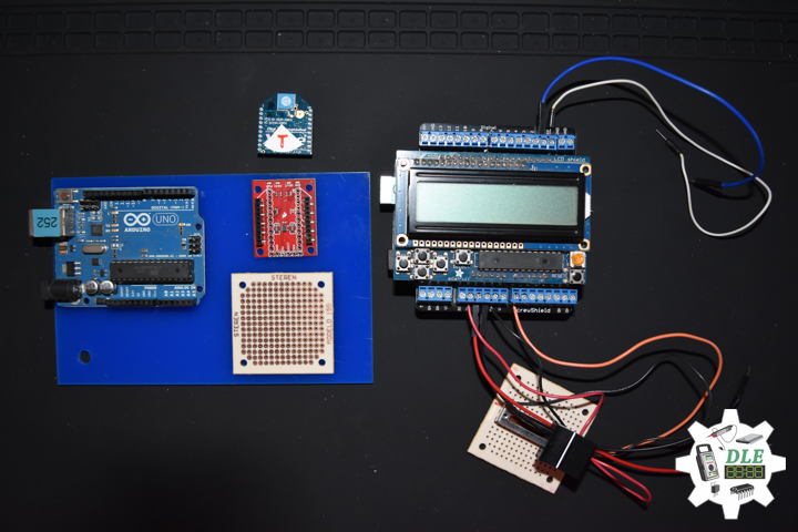
XBee Explorer Regulated
The XBee Explorer Regulated takes care of the 3.3V regulation, signal conditioning, and basic activity indicators. It translates the 5V serial signals to 3.3V so that you can connect a 5V system to any XBee module. The board was conveniently designed to mate directly with Arduino Pro boards for wireless bootloading and USB based configuration. This unit works with all XBee modules including the Series 1 and Series 2.5, standard and Pro versions. Plug an XBee into this breakout and you will have direct access to the serial and programming pins on the XBee unit and will be able to power the XBee with 5V.
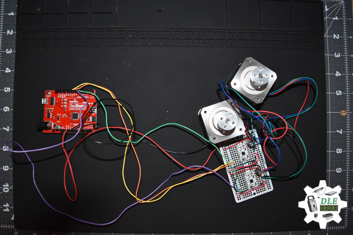
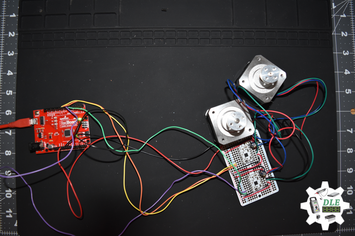
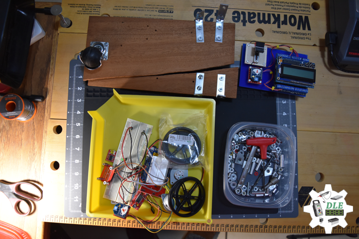
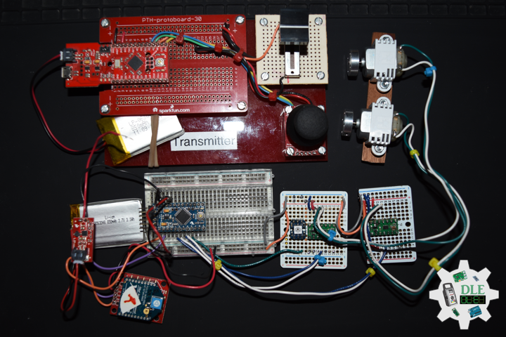
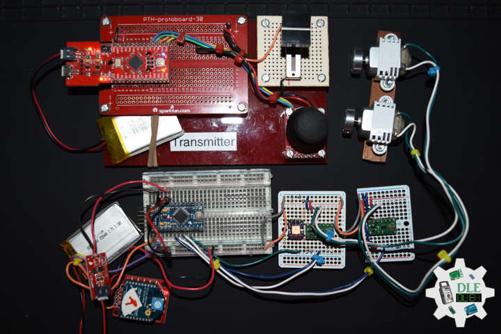
DL2201Mk03
1 x Fio v3 – ATmega32U4
1 x Arduino Pro Mini 328 – 5V/16MHz
1 x SparkFun FTDI Basic Breakout – 5V
1 x LiPower Boost Converter
2 x XBee S1
1 x XBee Explorer Regulated
2 x Lithium Ion Battery – 850mAh
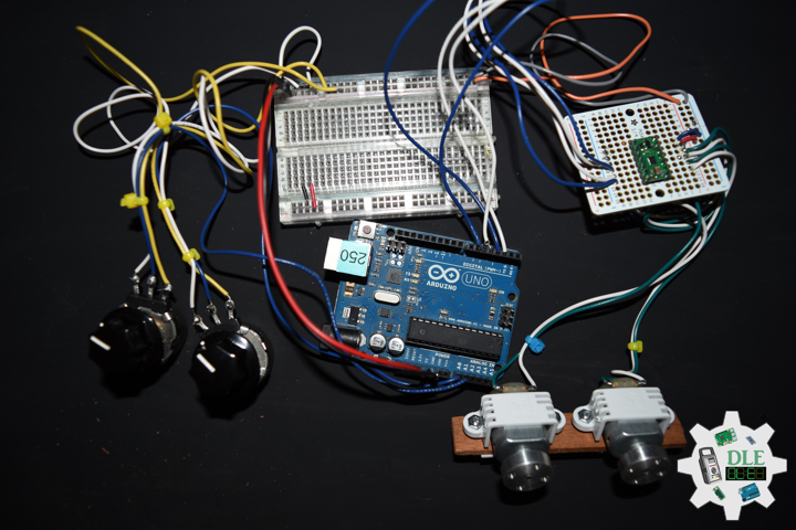
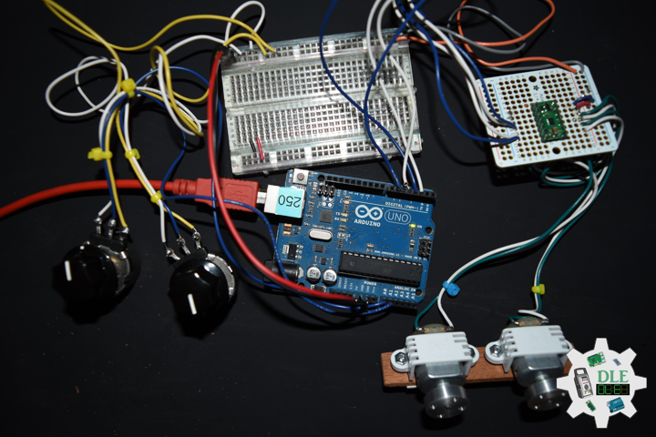
1 x Thumb Joystick
1 x SparkFun Thumb Joystick Breakout
1 x Slide Pot (Small)
1 x Slide Potentiometer Knob
1 x RGB Smart NeoPixel
2 x DRV8835 Dual Motor Driver Carrier
2 x Solarbotics RM2
2 x Pololu Universal Aluminum Mounting Hub 3mm Shaft, #4-40 Holes
2 x Pololu Mini Plastic Gearmotor Bracket Pair – Wide
1 x Half-Size Breadboard
2 x Adafruit Perma-Proto Quarter-Sized Breadboard
1 x SparkFun Cerberus USB Cable
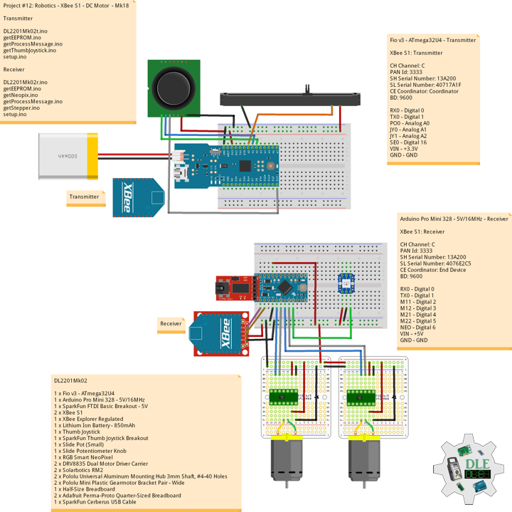
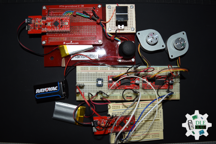
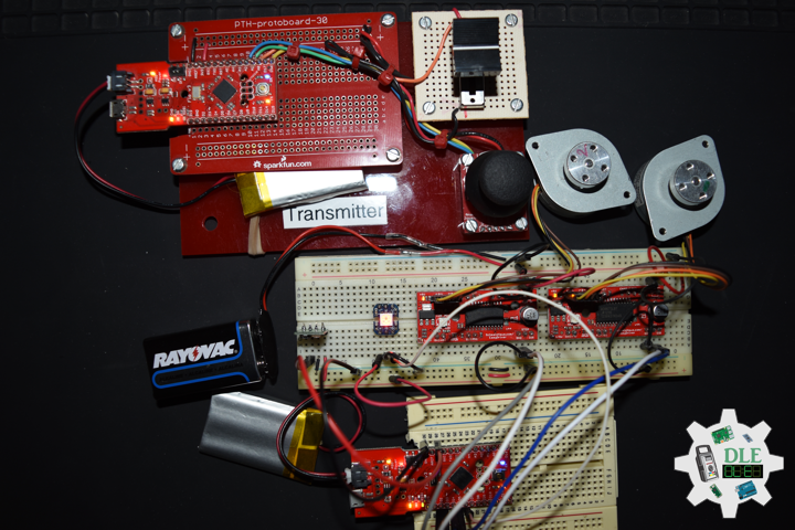
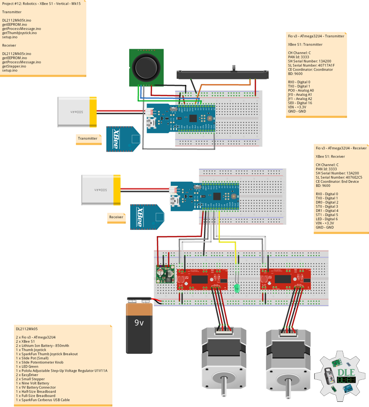
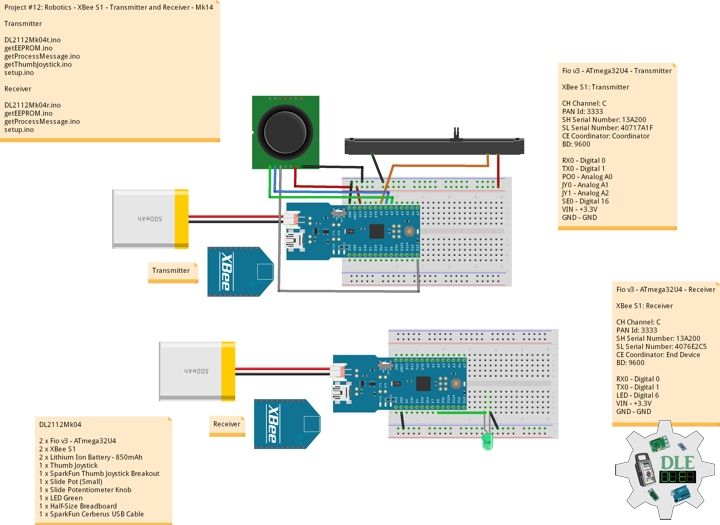
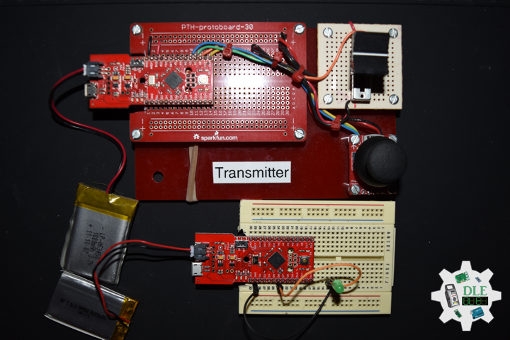
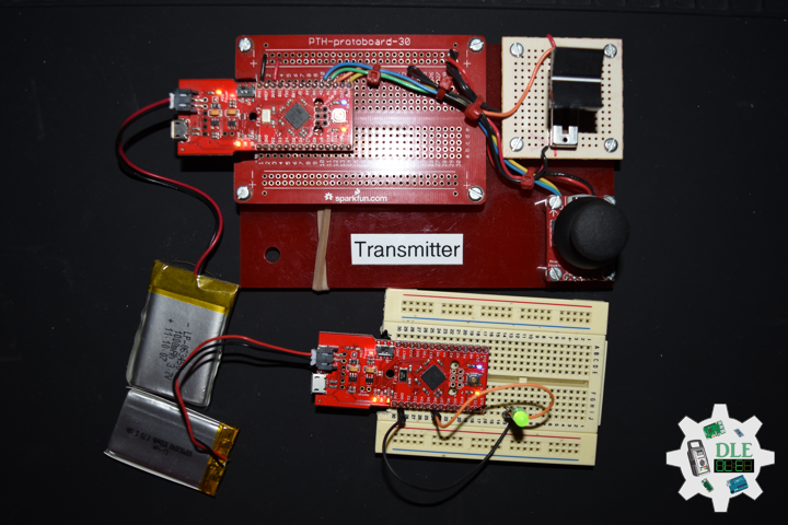
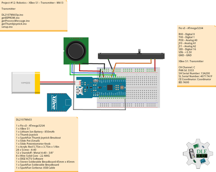
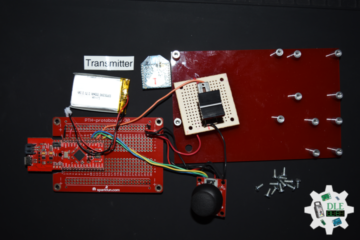
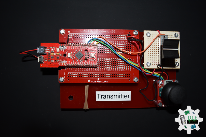
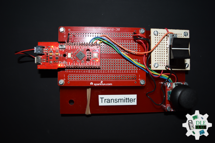
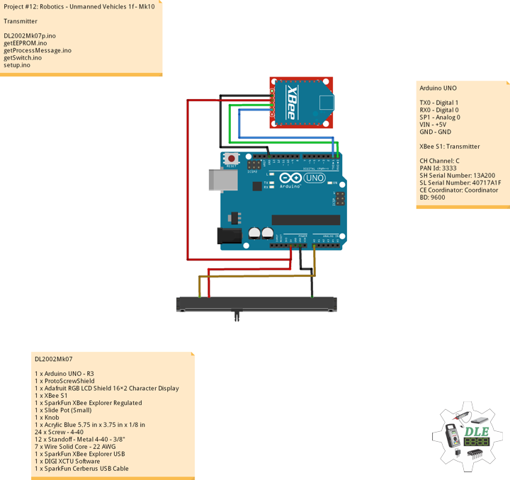
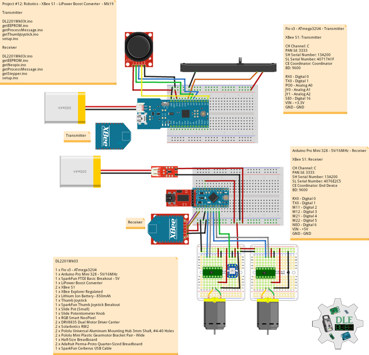
Fio v3 – ATmega32U4 – Transmitter
XBee S1: Transmitter
CH Channel: C
PAN Id: 3333
SH Serial Number: 13A200
SL Serial Number: 40717A1F
CE Coordinator: Coordinator
BD: 9600
RX0 – Digital 0
TX0 – Digital 1
PO0 – Analog A0
JY0 – Analog A1
JY1 – Analog A2
SE0 – Digital 16
VIN – +3.3V
GND – GND
——
DL2201Mk03t.ino
/* ***** Don Luc Electronics © *****
Software Version Information
Project #12: Robotics - LiPower Boost Converter - Mk19
01-03
DL2201Mk03t.ino
1 x Fio v3 - ATmega32U4
1 x XBee S1
1 x Lithium Ion Battery - 850mAh
1 x Thumb Joystick
1 x SparkFun Thumb Joystick Breakout
1 x Slide Pot (Small)
1 x Slide Potentiometer Knob
1 x SparkFun Cerberus USB Cable
*/

// Include the Library Code
// EEPROM library to read and write EEPROM with unique ID for unit
#include <EEPROM.h>

// Communication
unsigned long dTime = 200;

// Slide Pot (Small)
// Select the input pin for the slide pot
// Power
const int iSP1 = A0;
// Power to store the value
int iPower = 0;

// Connections to joystick
// Vertical
const int VERT = A1;
// Horizontal
const int HORIZ = A2;
// Pushbutton
const int SEL = 16;
// Initialize variables for analog and digital values
int vertical;
int horizontal;
int select;

// Software Version Information
// Version
String sver = "12-19t";
// Unit ID Information
// UID
String uid = "";

void loop()
{

  // Thumb Joystick
  isThumbJoystick();

  // Process Message
  isProcessMessage();

  delay( dTime );

}
getEEPROM.ino
// EEPROM
// is UID
void isUID()
{

  // Is Unit ID
  // UID
  uid = "";
  for (int x = 0; x < 5; x++)
  {
    uid = uid + char(EEPROM.read(x));
  }

}
getProcessMessage.ino
// Process Message
// isProcessMessage
void isProcessMessage() {

   // Loop through serial buffer
   // Print = "<" + vertical + "|" + horizontal + "|" + select + "|" + iValue + "|" + sver + "|" + uid + "*"

   Serial1.print( '<'  );
   Serial1.print( vertical );
   Serial1.print( '|' );
   Serial1.print( horizontal );
   Serial1.print( '|' );
   Serial1.print( select );
   Serial1.print( '|' );
   Serial1.print( iPower );
   Serial1.print( '|' );
   Serial1.print( sver );
   Serial1.print( '|' );
   Serial1.print( uid );
   Serial1.println( '*' );

}
getThumbJoystick.ino
// Thumb Joystick
void isThumbJoystick() {

  // Read all values from the joystick
  // Joystick was sitting around 520 for the vertical and horizontal values
  // Will be 0-1023
  vertical = analogRead(VERT);
  // Will be 0-1023
  horizontal = analogRead(HORIZ);
  // Will be HIGH (1) if not pressed, and LOW (0) if pressed
  select = digitalRead(SEL);
  // Read the value
  // Power be 0-1023
  iPower = analogRead( iSP1 );

}
setup.ino
// Setup
void setup()
{

  // EEPROM Unit ID
  isUID();

  // Pause
  delay(5);

  // Make the SEL line an input
  pinMode(SEL, INPUT_PULLUP);

  // Open Serial1 port at 9600 baud
  Serial1.begin( 9600 );

  // Pause
  delay(5);

}
——
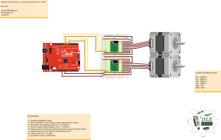
Arduino Pro Mini 328 – 5V/16MHz – Receiver
XBee S1: Receiver
CH Channel: C
PAN Id: 3333
SH Serial Number: 13A200
SL Serial Number: 4076E2C5
CE Coordinator: End Device
BD: 9600
RX0 – Digital 0
TX0 – Digital 1
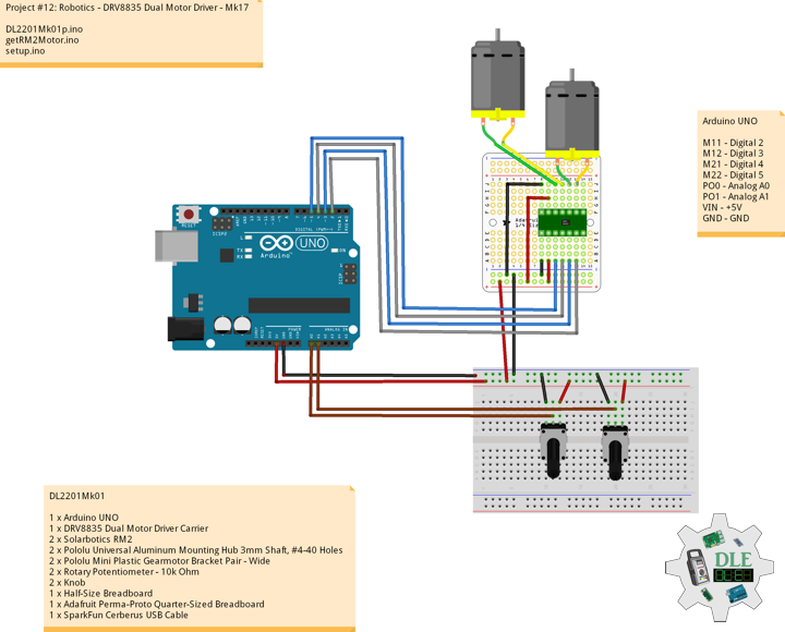
M11 – Digital 2
M12 – Digital 3
M21 – Digital 4
M22 – Digital 5
NEO – Digital 6
VIN – +5V
GND – GND
——
DL2201Mk03r.ino
/* ***** Don Luc Electronics © *****
Software Version Information
Project #12: Robotics - LiPower Boost Converter - Mk19
01-03
DL2201Mk03r.ino
1 x Arduino Pro Mini 328 - 5V/16MHz
1 x SparkFun FTDI Basic Breakout - 5V
1 x XBee S1
1 x XBee Explorer Regulated
1 x LiPower Boost Converter
1 x Lithium Ion Battery - 850mAh
1 x RGB Smart NeoPixel
2 x DRV8835 Dual Motor Driver Carrier
2 x Solarbotics RM2
2 x Pololu Universal Aluminum Mounting Hub 3mm Shaft, #4-40 Holes
2 x Pololu Mini Plastic Gearmotor Bracket Pair - Wide
1 x Half-Size Breadboard
2 x Adafruit Perma-Proto Quarter-Sized Breadboard
1 x SparkFun Cerberus USB Cable
*/

// Include the library code:
// EEPROM library to read and write EEPROM with unique ID for unit
#include <EEPROM.h>
// NeoPixels
#include <Adafruit_NeoPixel.h>

// Solarbotics RM2 -> 1
#define MOTOR1_IN1 2
#define MOTOR1_IN2 3
// Solarbotics RM2 -> 2
#define MOTOR2_IN1 4
#define MOTOR2_IN2 5

// Power be 0-1023
int iPower = 0;
String POW = "";
// Joystick was sitting around 520 for the vertical and horizontal values
// Will be 0-1023
// Vertical
int vertical;
String VER = "";
// Horizontal
// Will be 0-1023
int horizontal;
String HOR = "";
// Select
// Will be HIGH (1) if not pressed, and LOW (0) if pressed
int select1 = 0;
String SEL = "";
int firstClosingBracket = 0;
// Map Vertical and Horizontal
int mapVer = 0;
int mapHor = 0;
int iVer = 1;
int iHor = 0;

// NeoPixels
// On digital pin 6
#define PIN 6
// NeoPixels NUMPIXELS = 1
#define NUMPIXELS 1
// Pixels
Adafruit_NeoPixel pixels = Adafruit_NeoPixel(NUMPIXELS, PIN, NEO_GRB + NEO_KHZ800);
// Red
int red = 0;
// Green
int green = 0;
// Blue
int blue = 0;
// Neopix
int iNeo = 0;
// Value
int zz = 0;

// Process Message
// Start
bool bStart = false;
// End
bool bEnd   = false;
// Variable to store the incoming byte
int incb = 0;
// Message
String msg = "";
// Index
byte in = 0;
int x = 0;

// Software Version Information
String sver = "12-19r";
// Unit ID information
String uid = "";

void loop() {

  // Check for serial messages
  isProcessMessage();

}
getEEPROM.ino
// EEPROM
// isUID
void isUID()
{

  // Is Unit ID
  uid = "";
  for (int x = 0; x < 5; x++)
  {
    uid = uid + char(EEPROM.read(x));
  }

}
getNeopix.ino
// NeoPixels
// Neopix
void isNeopix()
{

    // Pixels
    pixels.setBrightness( 130 );
    // Pixels color takes RGB values, from 0,0,0 up to 255,255,255
    pixels.setPixelColor( iNeo, pixels.Color(red,green,blue) );
    // This sends the updated pixel color to the hardware
    pixels.show();
    // Delay for a period of time (in milliseconds)
    delay(50);

}
// isNUMPIXELS
void isNUMPIXELS()
{

  // Neopix Value
  switch ( zz ) {
    case 0:
      // NeoPixels Green
      // Red
      red = 0;
      // Green
      green = 255;
      // Blue
      blue = 0;
      // Neopix
      iNeo = 0;
      isNeopix();
      break;
    case 1:
      // NeoPixels Blue
      // Red
      red = 0;
      // Green
      green = 0;
      // Blue
      blue = 255;
      // Neopix
      iNeo = 0;
      isNeopix();
      break;
    case 2:
      // NeoPixels Red
      // Red
      red = 255;
      // Green
      green = 0;
      // Blue
      blue = 0;
      // Neopix
      iNeo = 0;
      isNeopix();
      break;
    case 3:
      // NeoPixels Yellow
      // Red
      red = 255;
      // Green
      green = 255;
      // Blue
      blue = 0;
      // Neopix
      iNeo = 0;
      isNeopix();
      break;
    case 4:
      // NeoPixels Magenta
      // Red
      red = 255;
      // Green
      green = 0;
      // Blue
      blue = 255;
      // Neopix
      iNeo = 0;
      isNeopix();
      break;
    case 5:
      // NeoPixels Cyan
      // Red
      red = 0;
      // Green
      green = 255;
      // Blue
      blue = 255;
      // Neopix
      iNeo = 0;
      isNeopix();
      break;
    case 6:
      // NeoPixels White
      // Red
      red = 255;
      // Green
      green = 255;
      // Blue
      blue = 255;
      // Neopix
      iNeo = 0;
      isNeopix();
      break;
  }

}
// isNUMPIXELSoff
void isNUMPIXELSoff()
{

   // Black Off
   // NeoPixels
   // Red
   red = 0;
   // Green
   green = 0;
   // Blue
   blue = 0;
   isNeopix();

}
getProcessMessage.ino
// ProcessMessage
// isProcessMessage
void isProcessMessage() {

  // Loop through serial buffer one byte at a time until you reach * which will be end of message
  while ( Serial.available() > 0 )
  {

      // Read the incoming byte:
      incb = Serial.read();

      // Start the message when the '<' symbol is received
      if(incb == '<')
      {

        // Start
        bStart = true;
        in = 0;
        msg = "";

      }
      // End the message when the '*' symbol is received
      else if(incb == '*')
      {

        // End
        bEnd = true;
        x = msg.length();
        msg.remove( x , 1);
        // Done reading

        break;
      }
      // Read the message
      else
      {

        // Message
        msg = msg + char(incb);
        in++;

      }

   }

   // Start - End
   if( bStart && bEnd)
   {

      // isRM2Motor => Message
      isRM2Motor();

      // Start - End
      in = 0;
      msg = "";
      bStart = false;
      bEnd = false;
      vertical;
      horizontal;
      iPower;

   }

}
getRM2Motor.ino
// RM2 Motor
// Setup RM2 Motor
void isSetupRM2Motor() {
// Solarbotics RM2 -> 1
pinMode(MOTOR1_IN1, OUTPUT);
pinMode(MOTOR1_IN2, OUTPUT);
// Solarbotics RM2 -> 2
pinMode(MOTOR2_IN1, OUTPUT);
pinMode(MOTOR2_IN2, OUTPUT);
}
// isRM2Motor
void isRM2Motor() {
// msg = vertical + "|" + horizontal + "|" + select + "|" + iValue + "|" + sver + "|" + uid
firstClosingBracket = 0;
// Vertical
firstClosingBracket = msg.indexOf('|');
VER = msg;
VER.remove(firstClosingBracket);
vertical = VER.toInt();
// Horizontal
firstClosingBracket = firstClosingBracket + 1;
msg.remove(0, firstClosingBracket );
firstClosingBracket = msg.indexOf('|');
HOR = msg;
HOR.remove(firstClosingBracket);
horizontal = HOR.toInt();
// Select
firstClosingBracket = firstClosingBracket + 1;
msg.remove(0, firstClosingBracket );
firstClosingBracket = msg.indexOf('|');
SEL = msg;
SEL.remove(firstClosingBracket);
select1 = SEL.toInt();
// Power
firstClosingBracket = firstClosingBracket + 1;
msg.remove(0, firstClosingBracket );
firstClosingBracket = msg.indexOf('|');
POW = msg;
POW.remove(firstClosingBracket);
iPower = POW.toInt();
// Set the direction
// Joystick was sitting around 520 for the vertical and horizontal values
// Will be 0-1023
mapVer = map(vertical, 0, 1023, -512, 512);
mapHor = map(horizontal, 0, 1023, -512, 512);
// Power
iPower = map(iPower, 0, 1023, 30, 200);
// Vertical and Horizontal
if ( mapVer == -512 ) {
// Down
// NeoPixels Blue
zz = 1;
isNUMPIXELS();
iVer = 1;
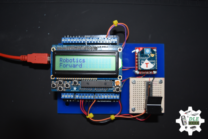
} else if ( mapVer == 512 ) {
// Up
// NeoPixels Green
zz = 0;
isNUMPIXELS();
iVer = 2;
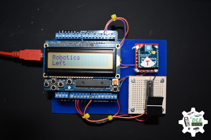
} else if ( mapHor == -512 ) {
// Left
// NeoPixels Yellow
zz = 3;
isNUMPIXELS();
iVer = 3;
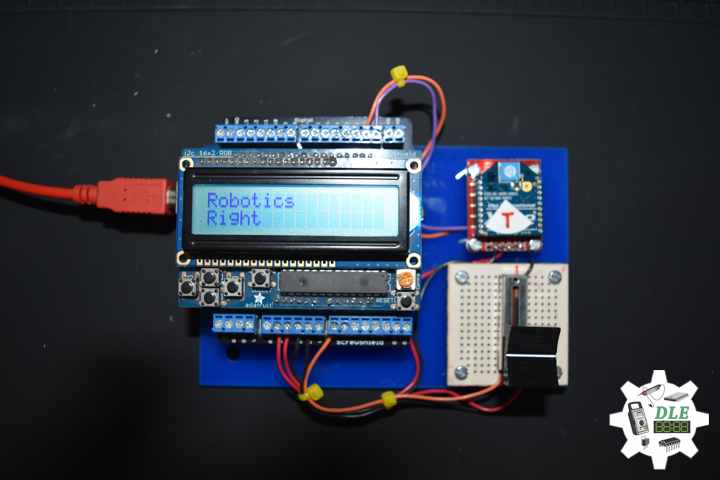
} else if ( mapHor == 512 ) {
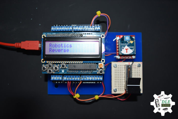
// Right
// NeoPixels Magenta
zz = 4;
isNUMPIXELS();
iVer = 4;
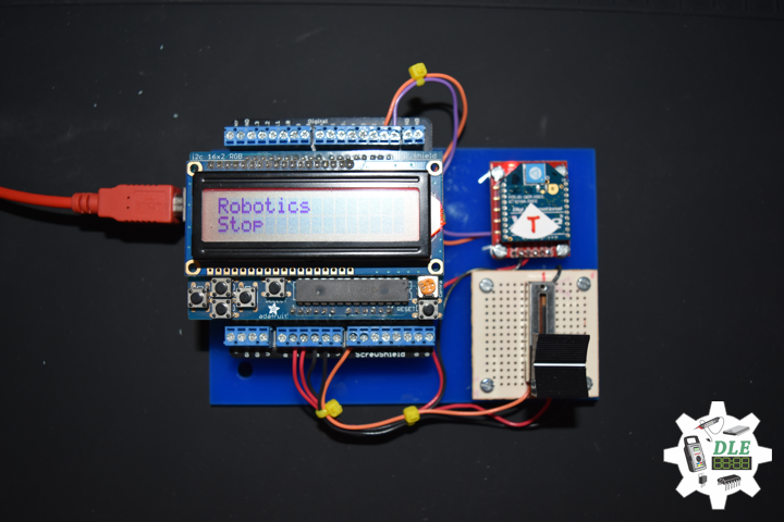
} else {
// Stop
// NeoPixels Red
zz = 2;
isNUMPIXELS();
iVer = 5;
}
// XBee Car
switch ( iVer ) {
case 1:
// Solarbotics RM2 -> 1 Forward
digitalWrite(MOTOR1_IN1, LOW);
analogWrite(MOTOR1_IN2, iPower);
delay(10);
// Solarbotics RM2 -> 2 Forward
digitalWrite(MOTOR2_IN1, LOW);
analogWrite(MOTOR2_IN2, iPower);
delay(10);
break;
case 2:
// Solarbotics RM2 -> 1 Backward
digitalWrite(MOTOR1_IN2, LOW);
analogWrite(MOTOR1_IN1, iPower);
delay(10);
// Solarbotics RM2 -> 2 Backward
digitalWrite(MOTOR2_IN2, LOW);
analogWrite(MOTOR2_IN1, iPower);
delay(10);
break;
case 3:
// Right
// Solarbotics RM2 -> 1 Forward
digitalWrite(MOTOR1_IN1, LOW);
analogWrite(MOTOR1_IN2, iPower);
delay(10);
// Solarbotics RM2 -> 2 Backward
digitalWrite(MOTOR2_IN2, LOW);
analogWrite(MOTOR2_IN1, iPower);
delay(10);
break;
case 4:
// Left
// Solarbotics RM2 -> 1 Backward
digitalWrite(MOTOR1_IN2, LOW);
analogWrite(MOTOR1_IN1, iPower);
delay(10);
// Solarbotics RM2 -> 2 Forward
digitalWrite(MOTOR2_IN1, LOW);
analogWrite(MOTOR2_IN2, iPower);
delay(10);
break;
case 5:
// Stop
// NeoPixels Red
//zz = 2;
//isNUMPIXELS();
// Solarbotics RM2 -> 1
digitalWrite(MOTOR1_IN1, LOW);
analogWrite(MOTOR1_IN2, 0);
delay(10);
// Solarbotics RM2 -> 2
digitalWrite(MOTOR2_IN1, LOW);
analogWrite(MOTOR2_IN2, 0);
delay(10);
break;
}
}
setup.ino
// Setup
void setup() {

  // Open the serial port at 9600 bps:
  Serial.begin( 9600 );

  // Pause
  delay(5);

  // EEPROM Unit ID
  isUID();

  // Pause
  delay(5);

  // Setup Solarbotics RM2 Motor
  isSetupRM2Motor();

  // Pause
  delay(5);

  // NeoPixels
  // This initializes the NeoPixel library
  pixels.begin();
  // Delay for a period of time (in milliseconds)
  delay(50);
  // isNUMPIXELS Off
  isNUMPIXELSoff();

}
——
People can contact us: https://www.donluc.com/?page_id=1927
Technology Experience
- Single-Board Microcontrollers (PIC, Arduino, Raspberry Pi,Espressif, etc…)
- IoT
- Robotics
- Camera and Video Capture Receiver Stationary, Wheel/Tank and Underwater Vehicle
- Unmanned Vehicles Terrestrial and Marine
- Research & Development (R & D)
- Desktop Applications (Windows, OSX, Linux, Multi-OS, Multi-Tier, etc…)
- Mobile Applications (Android, iOS, Blackberry, Windows Mobile, Windows CE, etc…)
- Web Applications (LAMP, Scripting, Java, ASP, ASP.NET, RoR, Wakanda, etc…)
- Social Media Programming & Integration (Facebook, Twitter, YouTube, Pinterest, etc…)
- Content Management Systems (WordPress, Drupal, Joomla, Moodle, etc…)
- Bulletin Boards (phpBB, SMF, Vanilla, jobberBase, etc…)
- eCommerce (WooCommerce, OSCommerce, ZenCart, PayPal Shopping Cart, etc…)
Instructor and E-Mentor
- IoT
- PIC Microcontrollers
- Arduino
- Raspberry Pi
- Espressif
- Robotics
- DOS, Windows, OSX, Linux, iOS, Android, Multi-OS
- Linux-Apache-PHP-MySQL
Follow Us
J. Luc Paquin – Curriculum Vitae – 2021 English & Español
https://www.jlpconsultants.com/luc/
Web: https://www.donluc.com/
Web: https://www.jlpconsultants.com/
Facebook: https://www.facebook.com/neosteam.labs.9/
YouTube: https://www.youtube.com/channel/UC5eRjrGn1CqkkGfZy0jxEdA
Twitter: https://twitter.com/labs_steam
Pinterest: https://www.pinterest.com/NeoSteamLabs/
Instagram: https://www.instagram.com/neosteamlabs/
Don Luc