——
#DonLuc #Environment #Microcontrollers #ESP32 #MQ-8 #GPS #SparkFun #Adafruit #Pololu #Fritzing #Programming #Arduino #Electronics #Consultant #Vlog #Aphasia
——
——
——
——
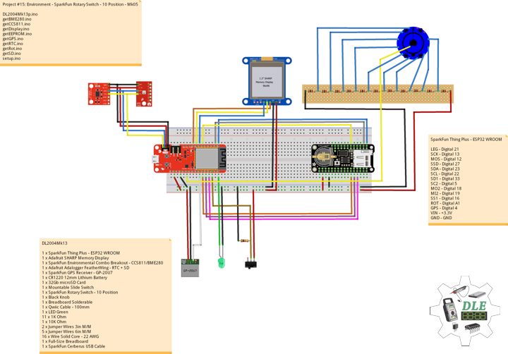
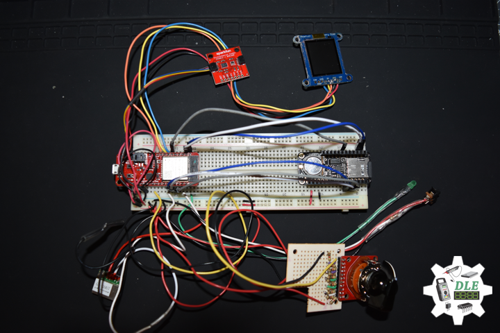
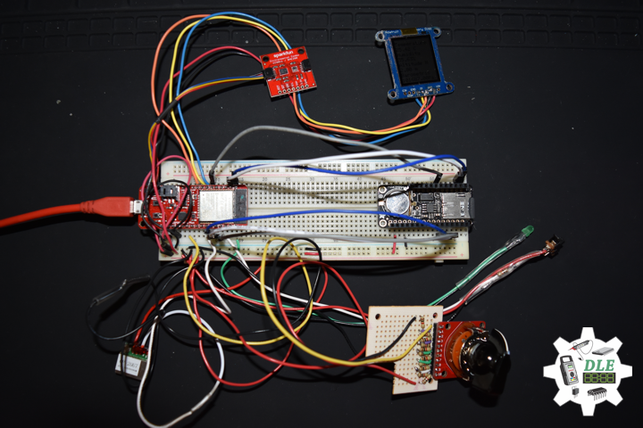
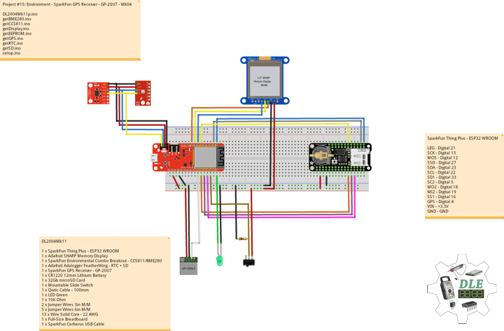
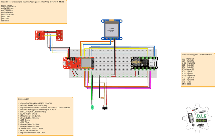
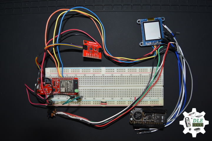
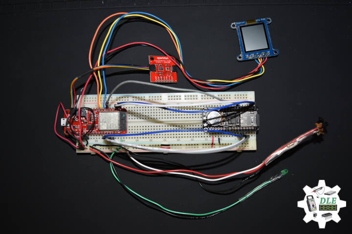
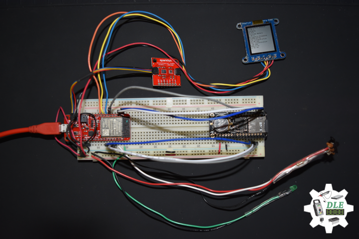
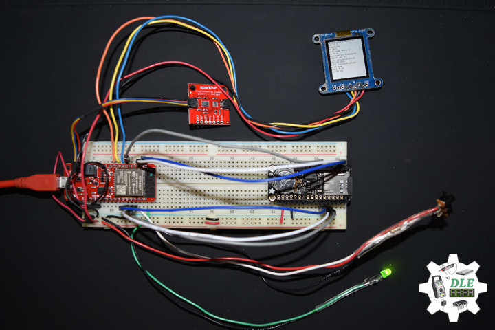
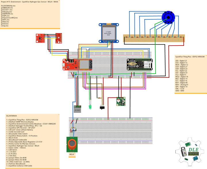
DL2005Mk04
1 x SparkFun Thing Plus – ESP32 WROOM
1 x Adafruit SHARP Memory Display
1 x SparkFun Environmental Combo Breakout – CCS811/BME280
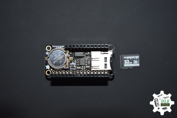
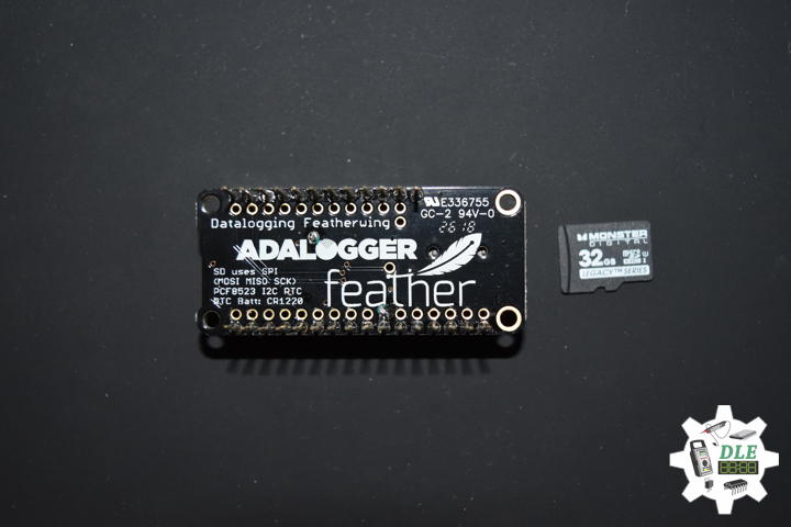
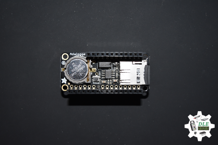
1 x Adafruit Adalogger FeatherWing – RTC + SD
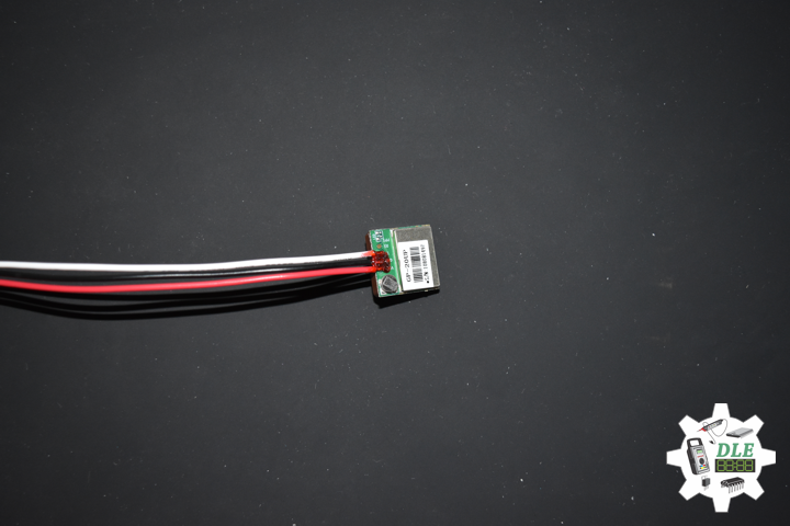
1 x SparkFun GPS Receiver – GP-20U7
1 x CR1220 12mm Lithium Battery
1 x 32Gb microSD Card
1 x Mountable Slide Switch
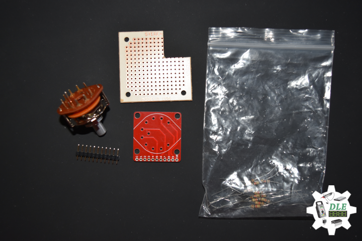
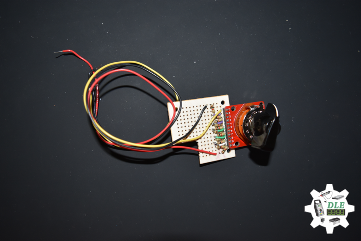
1 x SparkFun Rotary Switch – 10 Position
1 x Black Knob
1 x Breadboard Solderable
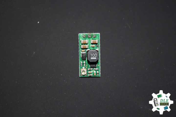
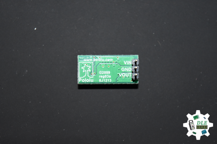
1 x Pololu Adjustable Boost Regulator 2.5-9.5V
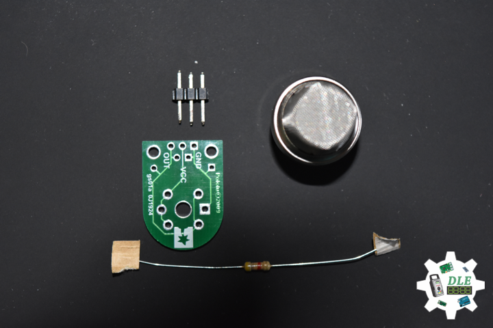
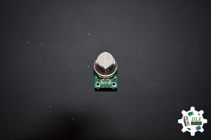
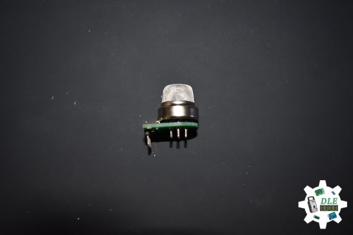
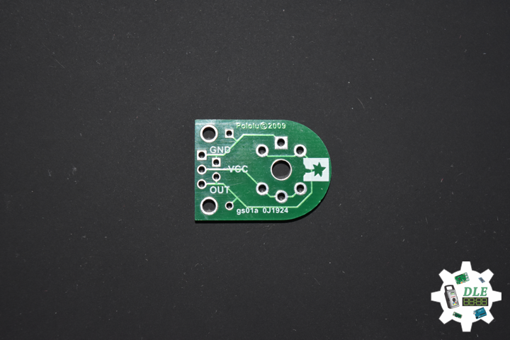
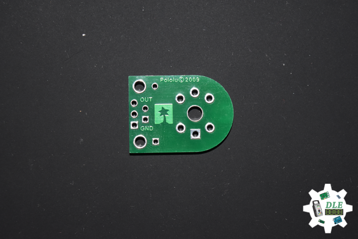
1 x Pololu Carrier for MQ Gas Sensors
1 x SparkFun Hydrogen Gas Sensor – MQ-8
1 x Qwiic Cable – 100mm
1 x LED Green
11 x 1K Ohm
1 x 4.7K Ohm
1 x 10K Ohm
4 x Jumper Wires 3in M/M
8 x Jumper Wires 6in M/M
16 x Wire Solid Core – 22 AWG
2 x Full-Size Breadboard
1 x SparkFun Cerberus USB Cable
SparkFun Thing Plus – ESP32 WROOM
LEG – Digital 21
SCK – Digital 13
MOS – Digital 12
SSD – Digital 27
SDA – Digital 23
SCL – Digital 22
SD1 – Digital 33
SC2 – Digital 5
MO2 – Digital 18
MI2 – Digital 19
SS1 – Digital 16
ROT – Analog A0
MH1 – Analog A1
GPS – Digital 14
VIN – +3.3V
GND – GND
DL2005Mk04p.ino
// ***** Don Luc Electronics © *****
// Software Version Information
// Project #15: Environment - SparkFun Hydrogen Gas Sensor - MQ-8 - Mk06
// 05-04
// DL2005Mk04p.ino 15-06
// EEPROM with Unique ID
// 1 x SparkFun Thing Plus - ESP32 WROOM
// 1 x Adafruit SHARP Memory Display
// 1 x SparkFun Environmental Combo Breakout - CCS811/BME280
// 1 x Adafruit Adalogger FeatherWing - RTC + SD
// 1 x SparkFun GPS Receiver - GP-20U7
// 1 x CR1220 12mm Lithium Battery
// 1 x 32Gb microSD Card
// 1 x Mountable Slide Switch
// 1 x SparkFun Rotary Switch - 10 Position
// 1 x Black Knob
// 1 x Breadboard Solderable
// 1 x Pololu Adjustable Boost Regulator 2.5-9.5V
// 1 x Pololu Carrier for MQ Gas Sensors
// 1 x SparkFun Hydrogen Gas Sensor - MQ-8
// 1 x Qwiic Cable - 100mm
// 1 x LED Green
// 11 x 1K Ohm
// 1 x 4.7K Ohm
// 1 x 10K Ohm
// 4 x Jumper Wires 3in M/M
// 8 x Jumper Wires 6in M/M
// 16 x Wire Solid Core - 22 AWG
// 2 x Full-Size Breadboard
// 1 x SparkFun Cerberus USB Cable

// Include the Library Code
// EEPROM Library to Read and Write EEPROM with Unique ID for Unit
#include "EEPROM.h"
// Wire
#include <Wire.h>
// SHARP Memory Display
#include <Adafruit_SharpMem.h>
#include <Adafruit_GFX.h>
// SparkFun CCS811 - eCO2 & tVOC
#include <SparkFunCCS811.h>
// SparkFun BME280 - Humidity, Temperature, Altitude and Barometric Pressure
#include <SparkFunBME280.h>
// Date and Time
#include "RTClib.h"
// SD Card
#include "FS.h"
#include "SD.h"
#include "SPI.h"
// GPS Receiver
#include <TinyGPS++.h>
// Hardware Serial
#include <HardwareSerial.h>

// LED Green
int iLEDGreen = 21;

// SHARP Memory Display
// any pins can be used
#define SHARP_SCK  13
#define SHARP_MOSI 12
#define SHARP_SS   27
// Set the size of the display here - 144x168
Adafruit_SharpMem display(SHARP_SCK, SHARP_MOSI, SHARP_SS, 144, 168);
// The currently-available SHARP Memory Display (144x168 pixels)
// requires > 4K of microcontroller RAM; it WILL NOT WORK on Arduino Uno
// or other <4K "classic" devices!
#define BLACK 0
#define WHITE 1
// 1/2 of lesser of display width or height
int minorHalfSize;

// SparkFun CCS811 - eCO2 & tVOC
// Default I2C Address
#define CCS811_ADDR 0x5B
CCS811 myCCS811(CCS811_ADDR);
float CCS811CO2 = 0;
float CCS811TVOC = 0;

// SparkFun BME280 - Humidity, Temperature, Altitude and Barometric Pressure
BME280 myBME280;
float BMEtempC = 0;
float BMEhumid = 0;
float BMEaltitudeM = 0;
float BMEpressure = 0;

// Date and Time
// PCF8523 Precision RTC
RTC_PCF8523 rtc;
String dateRTC = "";
String timeRTC = "";

// microSD Card
const int chipSelect = 33;
String zzzzzz = "";

// Mountable Slide Switch
int iSS1 = 16;
// State
int iSS1State = 0;

// ESP32 HardwareSerial
HardwareSerial tGPS(2);

// GPS Receiver
#define gpsRXPIN 14
// This one is unused and doesnt have a conection
#define gpsTXPIN 32
// The TinyGPS++ object
TinyGPSPlus gps;
float TargetLat;
float TargetLon;
int GPSStatus = 0;

// Rotary Switch - 10 Position
// Number 1 => 10
int iRotNum = A0;
// iRotVal - Value
int iRotVal = 0;
// Number
int z = 0;

// Gas Sensors MQ
// Hydrogen Gas Sensor - MQ-8
int iMQ8 = A1;
int iMQ8Raw = 0;
int iMQ8ppm = 0;
// Two points are taken from the curve in datasheet
// With these two points, a line is formed which is "approximately equivalent" to the original curve
float H2Curve[3] = {2.3, 0.93,-1.44};

// Software Version Information
String sver = "15-06";
// EEPROM Unique ID Information
#define EEPROM_SIZE 64
String uid = "";

void loop() {

  // Receives NEMA data from GPS receiver
  isGPS();

  // Date and Time
  isRTC();

  // SparkFun BME280 - Humidity, Temperature, Altitude and Barometric Pressure
  isBME280();

  // SparkFun CCS811 - eCO2 & tVOC
  isCCS811();

  // Gas Sensors MQ
  isGasSensor();

  // Rotary Switch
  isRot();

  // Slide Switch
  // Read the state of the iSS1 value
  iSS1State = digitalRead(iSS1);

  // If it is the Slide Switch State is HIGH
  if (iSS1State == HIGH) {

    // iLEDGreen
    digitalWrite(iLEDGreen,  HIGH );

    // microSD Card
    isSD();

  } else {

    // iLEDGreen
    digitalWrite(iLEDGreen,  LOW );

  }

  delay( 1000 );

}
getBME280.ino
// SparkFun BME280 - Humidity, Temperature, Altitude and Barometric Pressure
// isBME280 - Humidity, Temperature, Altitude and Barometric Pressure
void isBME280(){

  // Temperature Celsius
  BMEtempC = myBME280.readTempC();
  // Humidity
  BMEhumid = myBME280.readFloatHumidity();
  // Altitude Meters
  BMEaltitudeM = (myBME280.readFloatAltitudeMeters(), 2);
  // Barometric Pressure
  BMEpressure = myBME280.readFloatPressure();

}
getCCS811.ino
// CCS811 - eCO2 & tVOC
// isCCS811 - eCO2 & tVOC
void isCCS811(){

  // This sends the temperature & humidity data to the CCS811
  myCCS811.setEnvironmentalData(BMEhumid, BMEtempC);

  // Calling this function updates the global tVOC and eCO2 variables
  myCCS811.readAlgorithmResults();

  // eCO2 Concentration
  CCS811CO2 = myCCS811.getCO2();

  // tVOC Concentration
  CCS811TVOC = myCCS811.getTVOC();

}
getDisplay.ino
// Display
// SHARP Memory Display - UID
void isDisplayUID() {

    // Text Display
    // Clear Display
    display.clearDisplay();
    display.setRotation(4);
    display.setTextSize(3);
    display.setTextColor(BLACK);
    // Don Luc Electronics
    display.setCursor(0,10);
    display.println( "Don Luc" );
    display.setTextSize(2);
    display.setCursor(0,40);
    display.println( "Electronics" );
    // Version
    display.setTextSize(3);
    display.setCursor(0,70);
    display.println( "Version" );
    display.setTextSize(2);
    display.setCursor(0,100);
    display.println( sver );
    // EEPROM Unique ID
    display.setTextSize(1);
    display.setCursor(0,130);
    display.println( "EEPROM Unique ID" );
    display.setTextSize(2);
    display.setCursor(0,145);
    display.println( uid );
    // Refresh
    display.refresh();
    delay( 100 );

}
// Display Environmental
void isDisplayEnvironmental(){

    // Text Display Environmental
    // Clear Display
    display.clearDisplay();
    display.setRotation(4);
    display.setTextSize(1);
    display.setTextColor(BLACK);
    // Temperature Celsius
    display.setCursor(0,0);
    display.println( "Temperature Celsius" );
    display.setCursor(0,10);
    display.print( BMEtempC );
    display.println( " C" );
    // Humidity
    display.setCursor(0,20);
    display.println( "Humidity" );
    display.setCursor(0,30);
    display.print( BMEhumid );
    display.println( "%" );
    // Altitude Meters
    display.setCursor(0,40);
    display.println( "Altitude Meters" );
    display.setCursor(0,50);
    display.print( BMEaltitudeM );
    display.println( " m" );
    // Pressure
    display.setCursor(0,60);
    display.println( "Barometric Pressure" );
    display.setCursor(0,70);
    display.print( BMEpressure );
    display.println( " Pa" );
    // eCO2 Concentration
    display.setCursor(0,80);
    display.println( "eCO2 Concentration" );
    display.setCursor(0,90);
    display.print( CCS811CO2 );
    display.println( " ppm" );
    // tVOC Concentration
    display.setCursor(0,100);
    display.println( "tVOC Concentration" );
    display.setCursor(0,110);
    display.print( CCS811TVOC );
    display.println( " ppb" );
    // Date
    display.setCursor(0,120);
    display.println( dateRTC );
    // Time
    display.setCursor(0,130);
    display.println( timeRTC );
    // GPS Status
    display.setCursor(0,140);
    display.println( GPSStatus );
    // Target Latitude
    display.setCursor(0,150);
    display.println( TargetLat );
    // Target Longitude
    display.setCursor(0,160);
    display.println( TargetLon );
    // Refresh
    display.refresh();
    delay( 100 );

}
// Display Date
void isDisplayDate() {

    // Text Display Date
    // Clear Display
    display.clearDisplay();
    display.setRotation(4);
    display.setTextSize(2);
    display.setTextColor(BLACK);
    // Date
    display.setCursor(0,5);
    display.println( dateRTC );
    // Time
    display.setCursor(0,30);
    display.println( timeRTC );
    // GPS Status
    display.setCursor(0,60);
    display.print( "GPS: " );
    display.println( GPSStatus );
    // Target Latitude
    display.setCursor(0,80);
    display.println( "Latitude" );
    display.setCursor(0,100);
    display.println( TargetLat );
    // Target Longitude
    display.setCursor(0,120);
    display.println( "Longitude" );
    display.setCursor(0,140);
    display.println( TargetLon );
    // Refresh
    display.refresh();
    delay( 100 );

}
// Display BME280
void isDisplayBME280() {

     // Text Display BME280
    // Clear Display
    display.clearDisplay();
    display.setRotation(4);
    display.setTextSize(2);
    display.setTextColor(BLACK);
    // Temperature Celsius
    display.setCursor(0,10);
    display.println( "Temperature" );
    display.setCursor(0,30);
    display.print( BMEtempC );
    display.println( " C" );
    // Humidity
    display.setCursor(0,50);
    display.println( "Humidity" );
    display.setCursor(0,70);
    display.print( BMEhumid );
    display.println( "%" );
    // Altitude Meters
    display.setCursor(0,90);
    display.println( "Altitude M" );
    display.setCursor(0,110);
    display.print( BMEaltitudeM );
    display.println( " m" );
    // Pressure
    display.setCursor(0,130);
    display.println( "Barometric" );
    display.setCursor(0,150);
    display.print( BMEpressure );
    display.println( "Pa" );
    // Refresh
    display.refresh();
    delay( 100 );

}
// Display CCS811 - eCO2 & tVOC
void isDisplayCCS811() {

    // Text Display CCS811
    // Clear Display
    display.clearDisplay();
    display.setRotation(4);
    display.setTextSize(2);
    display.setTextColor(BLACK);
    // eCO2 Concentration
    display.setCursor(0,10);
    display.println( "eCO2" );
    display.setCursor(0,30);
    display.print( CCS811CO2 );
    display.println( " ppm" );
    // tVOC Concentration
    display.setCursor(0,60);
    display.println( "tVOC" );
    display.setCursor(0,80);
    display.print( CCS811TVOC );
    display.println( " ppb" );
    // Refresh
    display.refresh();
    delay( 100 );

}
// Display Gas Sensors MQ
void isDisplayMQ() {

    // Text Display MQ
    // Clear Display
    display.clearDisplay();
    display.setRotation(4);
    display.setTextSize(2);
    display.setTextColor(BLACK);
    // Gas Sensors MQ
    display.setCursor(0,5);
    display.println( "Gas H2 MQ8" );
    display.setCursor(0,25);
    display.print( iMQ8ppm );
    display.println( " ppm" );
    // Refresh
    display.refresh();
    delay( 100 );

}
// Display Z
void isDisplayZ() {

    // Text Display Z
    // Clear Display
    display.clearDisplay();
    display.setRotation(4);
    display.setTextSize(3);
    display.setTextColor(BLACK);
    // Z
    display.setCursor(0,10);
    display.print( "Z: " );
    display.println( z );
    // Refresh
    display.refresh();
    delay( 100 );

}
getEEPROM.ino
// EEPROM
// isUID EEPROM Unique ID
void isUID()
{

  // Is Unit ID
  uid = "";
  for (int x = 0; x < 5; x++)
  {
    uid = uid + char(EEPROM.read(x));
  }

}
getGPS.ino
// GPS Receiver
// Setup GPS
void setupGPS() {

  // Setup GPS
  tGPS.begin(  9600 , SERIAL_8N1, gpsRXPIN, gpsTXPIN );

}
// isGPS
void isGPS(){

  // Receives NEMA data from GPS receiver
  // This sketch displays information every time a new sentence is correctly encoded.
  while ( tGPS.available() > 0)
    if (gps.encode( tGPS.read() ))
    {
     displayInfo();
    }

  if (millis() > 5000 && gps.charsProcessed() < 10)
  {
    while(true);
  }

}
// GPS Vector Pointer Target
void displayInfo(){

  // Location
  if (gps.location.isValid())
  {

    TargetLat = gps.location.lat();
    TargetLon = gps.location.lng();
    GPSStatus = 2;

  }
  else
  {

    GPSStatus = 0;

  }

}
getGasSensorMQ.ino
// Gas Sensors MQ
// Gas Sensor
void isGasSensor() {

  // Read in analog value from each gas sensors

  // Hydrogen Gas Sensor - MQ-8
  iMQ8Raw = analogRead( iMQ8 );

  // Caclulate the PPM of each gas sensors

  // Hydrogen Gas Sensor - MQ-8
  iMQ8ppm = isMQ8( iMQ8Raw );

}
// Hydrogen Gas Sensor - MQ-8 - PPM
int isMQ8(double rawValue) {

  // RvRo
  double RvRo = rawValue * (3.3 / 1023);

  return (pow(4.7,( ((log(RvRo)-H2Curve[1])/H2Curve[2]) + H2Curve[0])));

}
getRTC.ino
// Date & Time
// PCF8523 Precision RTC
void setupRTC() {

  // Date & Time
  // pcf8523 Precision RTC
  if (! rtc.begin()) {
    while (1);
  }

  if (! rtc.initialized()) {
    // Following line sets the RTC to the date & time this sketch was compiled
    rtc.adjust(DateTime(F(__DATE__), F(__TIME__)));
    // This line sets the RTC with an explicit date & time, for example to set
    // January 21, 2014 at 3am you would call:
    // rtc.adjust(DateTime(2018, 9, 29, 12, 17, 0));
  }

}
// Date and Time RTC
void isRTC () {

  // Date and Time
  dateRTC = "";
  timeRTC = "";
  DateTime now = rtc.now();

  // Date
  dateRTC = now.year(), DEC;
  dateRTC = dateRTC + "/";
  dateRTC = dateRTC + now.month(), DEC;
  dateRTC = dateRTC + "/";
  dateRTC = dateRTC + now.day(), DEC;

  // Time
  timeRTC = now.hour(), DEC;
  timeRTC = timeRTC + ":";
  timeRTC = timeRTC + now.minute(), DEC;
  timeRTC = timeRTC + ":";
  timeRTC = timeRTC + now.second(), DEC;

}
getRot.ino
// Rotary Switch
// isRot - iRotVal - Value
void isRot() {

  // Rotary Switch
  z = analogRead( iRotNum );

  // Rotary Switch - 10 Position
  // Number 1 => 10
  if ( z >= 3600 ) {

    // Z
    iRotVal = 10;

  } else if ( z >= 3200 ) {

    // Z
    iRotVal = 9;

  } else if ( z >= 2700 ) {

    // Z
    iRotVal = 8;

  } else if ( z >= 2400 ) {

    // Z
    iRotVal = 7;

  } else if ( z >= 2000 ) {

    // Z
    iRotVal = 6;

  } else if ( z >= 1600 ) {

    // Z
    iRotVal = 5;

  } else if ( z >= 1200 ) {

    // Z
    iRotVal = 4;

  } else if ( z >= 900 ) {

    // Z
    iRotVal = 3;

  } else if ( z >= 500 ) {

    // Z
    iRotVal = 2;

  } else {

    // Z
    iRotVal = 1;

  }

  // Range Value
  switch ( iRotVal ) {
    case 1:

      // Display Environmental
      isDisplayEnvironmental();

      break;
    case 2:

      // Display Date
      isDisplayDate();

      break;
    case 3:

      // Display BME280
      isDisplayBME280();

      break;
    case 4:

      // Display CCS811 - eCO2 & tVOC
      isDisplayCCS811();

      break;
    case 5:

      // Display Gas Sensors MQ
      isDisplayMQ();

      break;
    case 6:

      // Display UID
      isDisplayUID();

      break;
    case 7:

      // Z
      isDisplayZ();

      break;
    case 8:

      // Z
      isDisplayZ();

      break;
    case 9:

      // Z
      isDisplayZ();

      break;
    case 10:

      // Z
      isDisplayZ();

      break;
  }

}
getSD.ino
// microSD Card
// microSD Setup
void setupSD() {

    // microSD Card
    pinMode( chipSelect , OUTPUT );
    if(!SD.begin( chipSelect )){
        ;
        return;
    }

    uint8_t cardType = SD.cardType();

    // CARD NONE
    if(cardType == CARD_NONE){
        ;
        return;
    }

    // SD Card Type
    if(cardType == CARD_MMC){
        ;
    } else if(cardType == CARD_SD){
        ;
    } else if(cardType == CARD_SDHC){
        ;
    } else {
        ;
    }

    // Size
    uint64_t cardSize = SD.cardSize() / (1024 * 1024);

}
// microSD Card
void isSD() {

  zzzzzz = "";

  // EEPROM Unique ID|Version|Date|Time|GPS Status|Target Latitude|Target Longitude|Temperature Celsius|Humidity|Altitude Meters|Barometric Pressure|eCO2 Concentration|tVOC Concentration|H2 Gas Sensor MQ-8
  zzzzzz = uid + "|" + sver + "|" + dateRTC + "|" + timeRTC + "|" + GPSStatus + "|" + TargetLat + "|" + TargetLon + "|" + BMEtempC + "|" + BMEhumid + "|" + BMEaltitudeM + "|" + BMEpressure + "|" + CCS811CO2 + "|" + CCS811TVOC + "|" + iMQ8ppm + "|\r";

  char msg[zzzzzz.length() + 1];

  zzzzzz.toCharArray(msg, zzzzzz.length() + 1);

  // Append File
  appendFile(SD, "/espdata.txt", msg );

}
// List Dir
void listDir(fs::FS &fs, const char * dirname, uint8_t levels){

    // List Dir
    dirname;

    File root = fs.open(dirname);

    if(!root){
        return;
    }

    if(!root.isDirectory()){
        return;
    }

    File file = root.openNextFile();

    while(file){
        if(file.isDirectory()){
            file.name();
            if(levels){
                listDir(fs, file.name(), levels -1);
            }
        } else {
            file.name();
            file.size();
        }
        file = root.openNextFile();
    }

}
// Write File
void writeFile(fs::FS &fs, const char * path, const char * message){

    // Write File
    path;

    File file = fs.open(path, FILE_WRITE);

    if(!file){
        return;
    }

    if(file.print(message)){
        ;
    } else {
        ;
    }

    file.close();

}
// Append File
void appendFile(fs::FS &fs, const char * path, const char * message){

    // Append File
    path;

    File file = fs.open(path, FILE_APPEND);

    if(!file){
        return;
    }

    if(file.print(message)){
        ;
    } else {
        ;
    }

    file.close();

}
setup.ino
// Setup
void setup() {

  // EEPROM Size
  EEPROM.begin(EEPROM_SIZE);

  // EEPROM Unique ID
  isUID();

  // GPS Receiver
  // Setup GPS
  setupGPS();

  // SHARP Display Start & Clear the Display
  display.begin();
  // Clear Display
  display.clearDisplay();

  // Display UID
  isDisplayUID();

  // Wire - Inialize I2C Hardware
  Wire.begin();

  // SparkFun BME280 - Humidity, Temperature, Altitude and Barometric Pressure
  myBME280.begin();

  // CCS811 - eCO2 & tVOC
  myCCS811.begin();

  // Initialize the LED Green
  pinMode(iLEDGreen, OUTPUT);

  // Date & Time RTC
  // PCF8523 Precision RTC
  setupRTC();

  // Date & Time
  isRTC();

  // microSD Card
  setupSD();

  // Slide Switch
  pinMode(iSS1, INPUT);

  delay( 5000 );

}
Technology Experience
- Research & Development (R & D)
- Desktop Applications (Windows, OSX, Linux, Multi-OS, Multi-Tier, etc…)
- Mobile Applications (Android, iOS, Blackberry, Windows Mobile, Windows CE, etc…)
- Web Applications (LAMP, Scripting, Java, ASP, ASP.NET, RoR, Wakanda, etc…)
- Social Media Programming & Integration (Facebook, Twitter, YouTube, Pinterest, etc…)
- Content Management Systems (WordPress, Drupal, Joomla, Moodle, etc…)
- Bulletin Boards (phpBB, SMF, Vanilla, jobberBase, etc…)
- eCommerce (WooCommerce, OSCommerce, ZenCart, PayPal Shopping Cart, etc…)
Instructor
- DOS, Windows, OSX, Linux, iOS, Android, Multi-OS
- Linux-Apache-PHP-MySQL
- Robotics
- Arduino
- Raspberry Pi
- Espressif
Follow Us
The Alpha Geek
Aphasia
J. Luc Paquin – Curriculum Vitae
https://www.donluc.com/DLHackster/LucPaquinCVEngMk2020a.pdf
Web: https://www.donluc.com/
Web: http://www.jlpconsultants.com/
Web: https://www.donluc.com/DLHackster/
Web: https://www.hackster.io/neosteam-labs
Facebook: https://www.facebook.com/neosteam.labs.9/
YouTube: https://www.youtube.com/channel/UC5eRjrGn1CqkkGfZy0jxEdA
Twitter: https://twitter.com/labs_steam
Pinterest: https://www.pinterest.com/NeoSteamLabs/
Don Luc