——
——
——
——
——
——
——
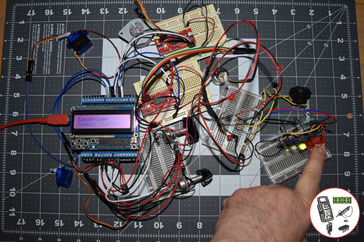
SparkFun 5-Way Tactile Switch Breakout
This 5-way tactile switch (up, down, left, right, and center click) allows for joystick-like control in a very small package.
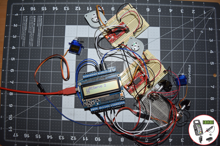
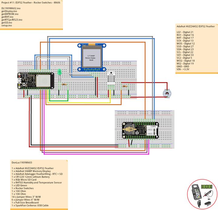
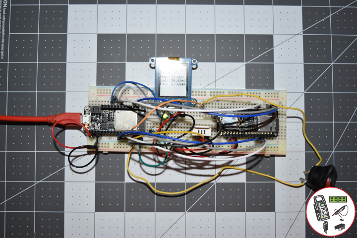
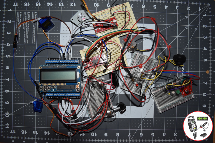
DL1912Mk03
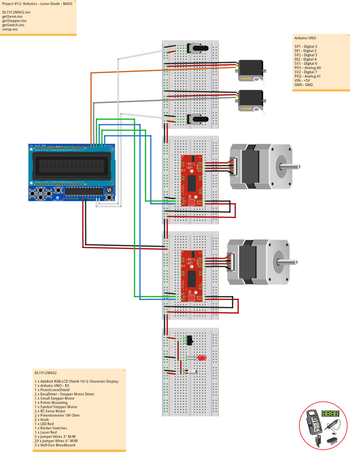
1 x Adafruit RGB LCD Shield 16×2 Character Display
1 x Arduino UNO – R3
1 x ProtoScrewShield
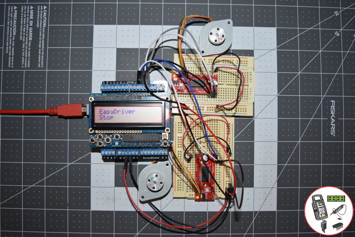
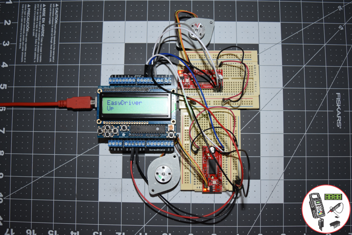
2 x EasyDriver – Stepper Motor Driver
1 x Small Stepper Motor
1 x Pololu Mounting
1 x Symbol Stepper Motor
2 x RC Servo Motor
2 x Potentiometer 1M Ohm
2 x Knob
2 x LED Red
1 x Rocker Switches
1 x Laser Red
1 x SparkFun 5-Way Tactile Switch Breakout
1 x LED Green
1 x LED Bi-Colour
1 x LED Yellow
17 x Jumper Wires 3″ M/M
31 x Jumper Wires 6″ M/M
4 x Half-Size Breadboard
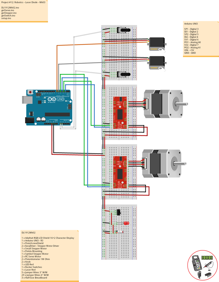
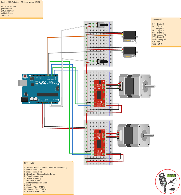
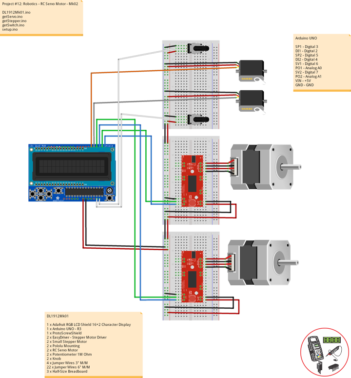
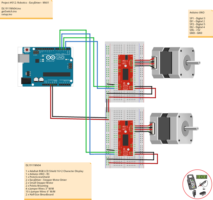
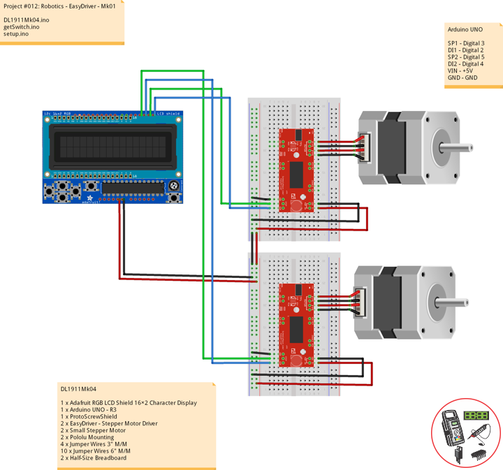
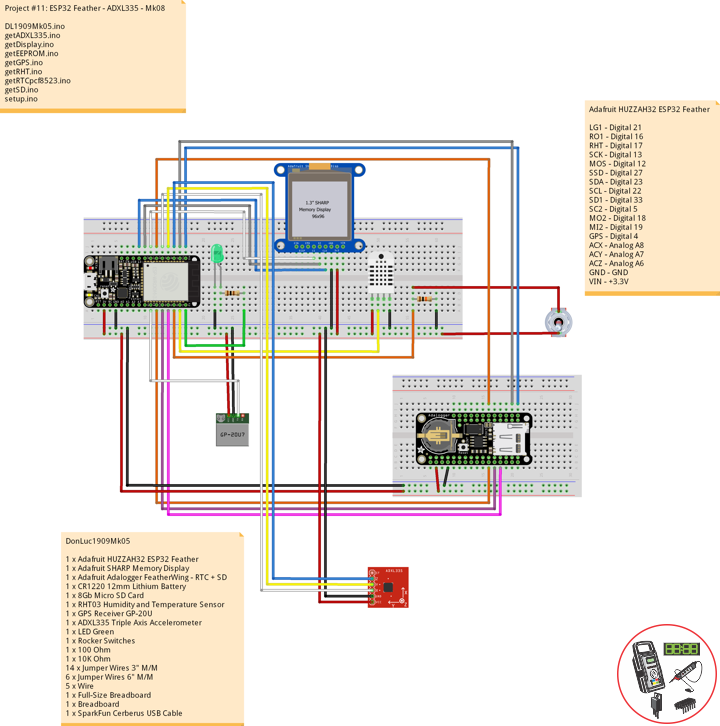
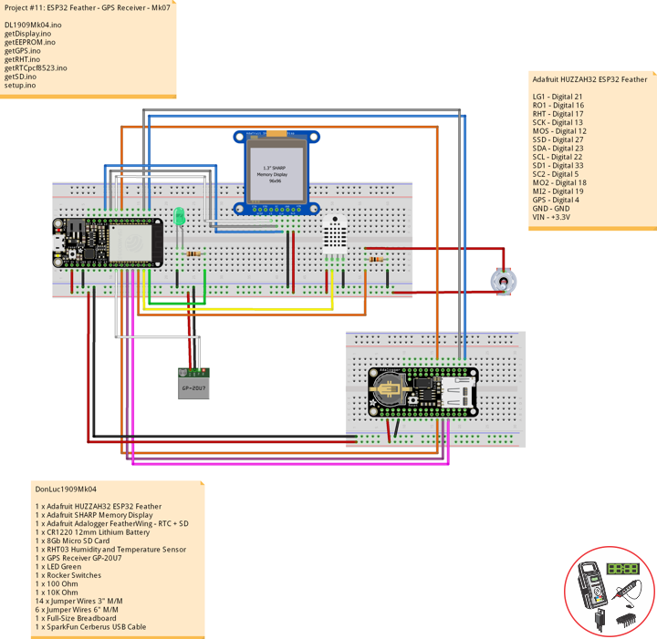
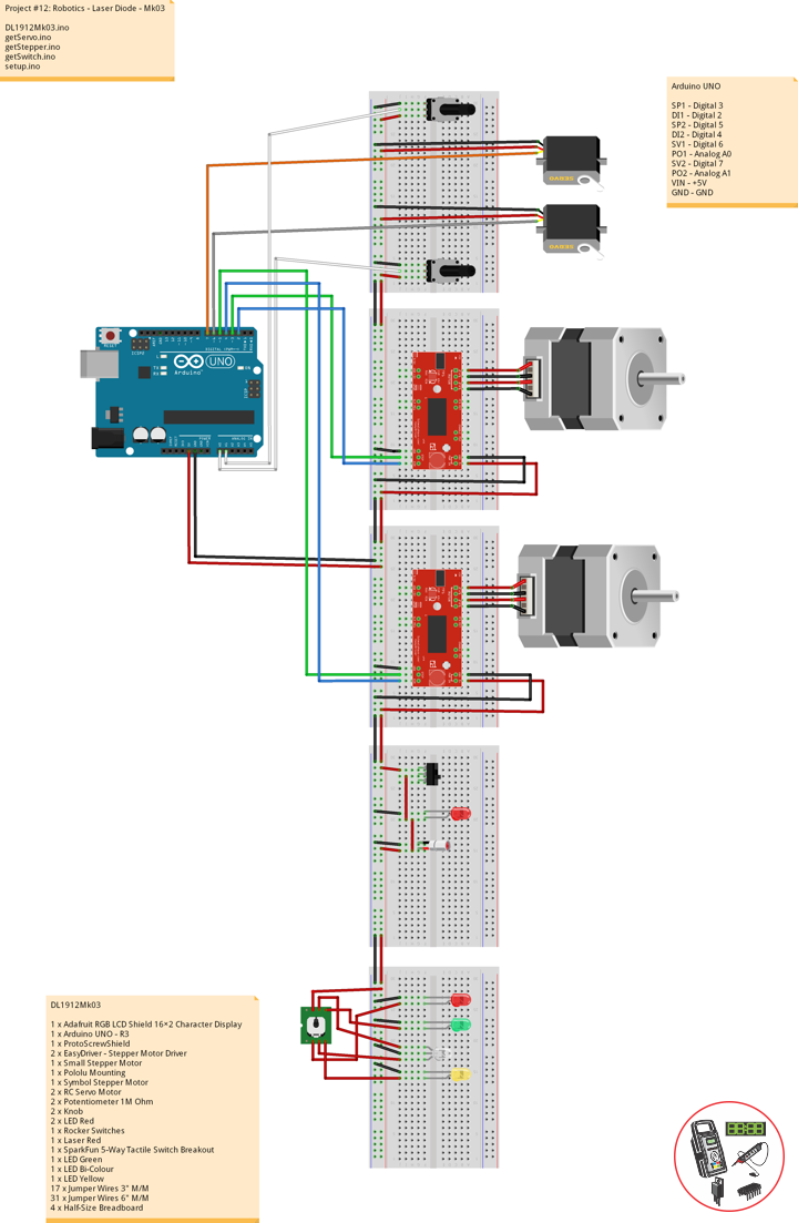
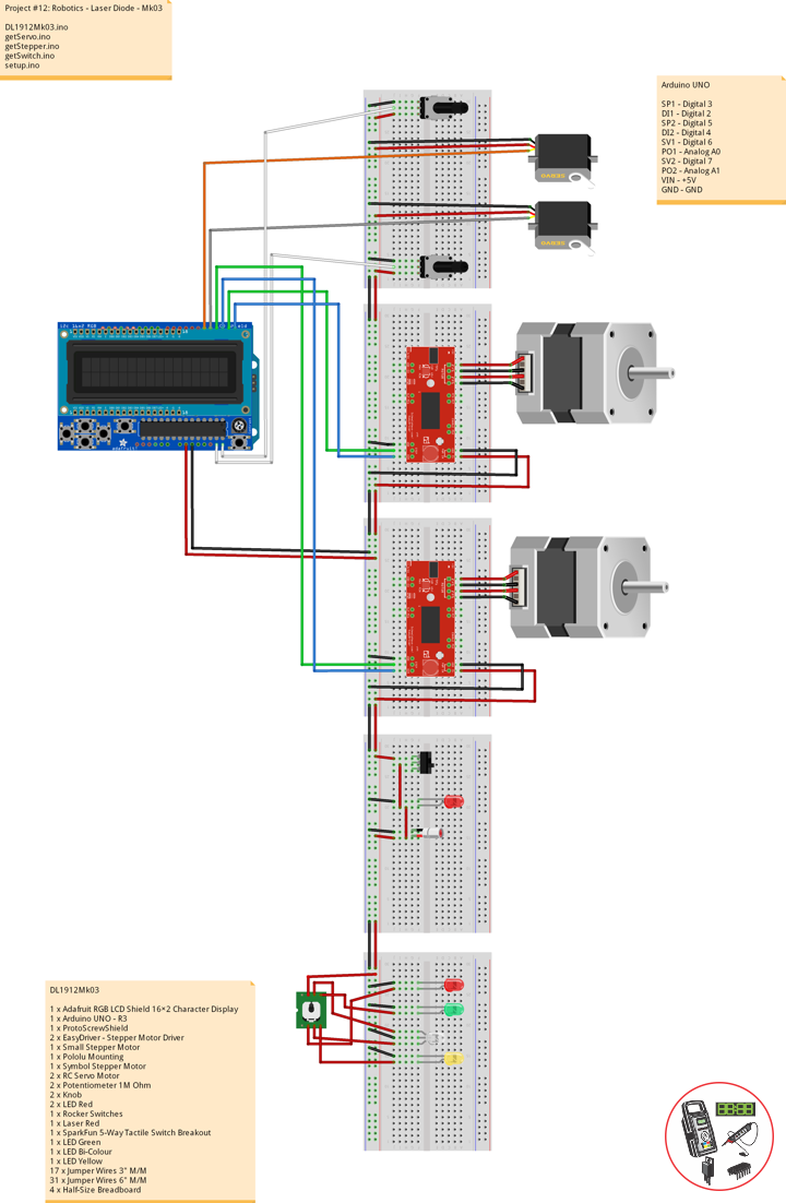
Arduino UNO
SP1 – Digital 3
DI1 – Digital 2
SP2 – Digital 5
DI2 – Digital 4
SV1 – Digital 6
PO1 – Analog A0
SV2 – Digital 7
PO2 – Analog A1
VIN – +5V
GND – GND
DL1912Mk03.ino
// ***** Don Luc Electronics © *****
// Software Version Information
// Project #12: Robotics - 5-Way Switch - Mk04
// 12-03
// DL1912Mk02p.ino 12-04
// Arduino UNO
// Screw Shield
// Adafruit RGB LCD Shield
// 1 x Small Stepper Motor
// 1 x Symbol Stepper Motor
// 2 x EasyDriver
// 2 x RC Servo Motor
// 2 x Potentiometer
// 2 x LED Red
// 1 x Rocker Switches
// 1 x Laser Red
// 1 x SparkFun 5-Way Tactile Switch Breakout
// 1 x LED Green
// 1 x LED Bi-Colour
// 1 x LED Yellow

// include the library code:
#include <Adafruit_RGBLCDShield.h>
#include <Servo.h>

// Adafruit RGB LCD Shield
Adafruit_RGBLCDShield RGBLCDShield = Adafruit_RGBLCDShield();

// These #defines make it easy to set the backlight color
#define OFF 0x0
#define RED 0x1
#define YELLOW 0x3
#define GREEN 0x2
#define TEAL 0x6
#define BLUE 0x4
#define VIOLET 0x5
#define WHITE 0x7

// Momentary Button
int yy = 0;
uint8_t momentaryButton = 0;

// 2 x EasyDriver
int dirPinR = 2;                           // EasyDriver Right
int stepPinR = 3;                          // stepPin Right
int dirPinL = 4;                           // EasyDriver Left
int stepPinL = 5;                          // stepPin Left
int i = 0;

// 2 x RC Servo Motor
// 2 x Potentiometer
Servo isRCServo1;                          // Create servo object to control a RCServo1
int servo1 = 6;                            // Servo 1
int iPot1 = A0;                            // Analog Potentiometer 1
int iVal1;                                 // Variable - Analog Potentiometer 1
Servo isRCServo2;                          // Create servo object to control a RCServo2
int servo2 = 7;                            // Servo 2
int iPot2 = A1;                            // Analog Potentiometer 2
int iVal2;                                 // Variable - Analog Potentiometer 2

void loop() {

  // Clear
  RGBLCDShield.clear();

  // Momentary Button
  momentaryButton = RGBLCDShield.readButtons();

  switch ( yy ) {
    case 1:

      // Up
      isSwitch1();

      break;
    case 2:

      // Down
      isSwitch2();

      break;
    case 3:

      // Right
      isSwitch3();

      break;
    case 4:

      // Left
      isSwitch4();

      break;
    case 5:

      // Stop
      isSwitch5();

      break;
    default:

      // Stop
      yy = 5;
      RGBLCDShield.setBacklight(RED);
      isSwitch5();

   }

   if ( momentaryButton ) {

    if ( momentaryButton & BUTTON_UP ) {

      yy = 1;
      // Up
      RGBLCDShield.setBacklight(GREEN);

    }

    if ( momentaryButton & BUTTON_DOWN ) {

      yy = 2;
      // Down
      RGBLCDShield.setBacklight(VIOLET);

    }

    if ( momentaryButton & BUTTON_LEFT ) {

      yy = 3;
      // Right
      RGBLCDShield.setBacklight(TEAL);

    }

    if ( momentaryButton & BUTTON_RIGHT ) {

      yy = 4;
      // Left
      RGBLCDShield.setBacklight(YELLOW);
    }

    if ( momentaryButton & BUTTON_SELECT ) {

      yy = 5;
      // Stop
      RGBLCDShield.setBacklight(RED);

    }

  }

}
getServo.ino
// Servo
// isServoSetup
void isServoSetup() {
// 2 x RC Servo Motor
isRCServo1.attach( servo1 );
isRCServo2.attach( servo2 );
}
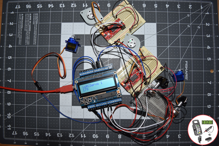
// isServo1
void isServo1() {
// EasyDriver
isStepperStop();
// Potentiometer RC Servo Motor 1
iVal1 = analogRead( iPot1 ); // Reads the value of the iPot1 (Value between 0 and 1023)
iVal1 = map(iVal1, 0, 1023, 0, 180); // Scale it to use it with the isRCServo1 (Value between 0 and 180)
isRCServo1.write( iVal1 ); // isRCServo1 sets the servo position according to the scaled value
delay(15);
// Display
// Set the cursor to column 0, line 0
RGBLCDShield.setCursor(0,0);
RGBLCDShield.print("RC Servo 1"); // RC Servo 1
// Set the cursor to column 0, line 1
RGBLCDShield.setCursor(0, 1);
RGBLCDShield.print( iVal1 ); // Reads the value iVal1
delay(500);
}
// isServo2
void isServo2() {
// EasyDriver
isStepperStop();
// Potentiometer RC Servo Motor 1
iVal2 = analogRead( iPot2 ); // Reads the value of the iPot2 (Value between 0 and 1023)
iVal2 = map(iVal2, 0, 1023, 0, 180); // Scale it to use it with the isRCServo2 (Value between 0 and 180)
isRCServo2.write( iVal2 ); // isRCServo2 sets the servo position according to the scaled value
delay(15);
// Display
// Set the cursor to column 0, line 0
RGBLCDShield.setCursor(0,0);
RGBLCDShield.print("RC Servo 2"); // RC Servo 2
// Set the cursor to column 0, line 1
RGBLCDShield.setCursor(0, 1);
RGBLCDShield.print( iVal2 ); // Reads the value iVal2
delay(500);
}
getStepper.ino
// Stepper
// isStepperSetup
void isStepperSetup() {
// 2 x EasyDriver
pinMode(dirPinR, OUTPUT);
pinMode(stepPinR, OUTPUT);
pinMode(dirPinL, OUTPUT);
pinMode(stepPinL, OUTPUT);
}
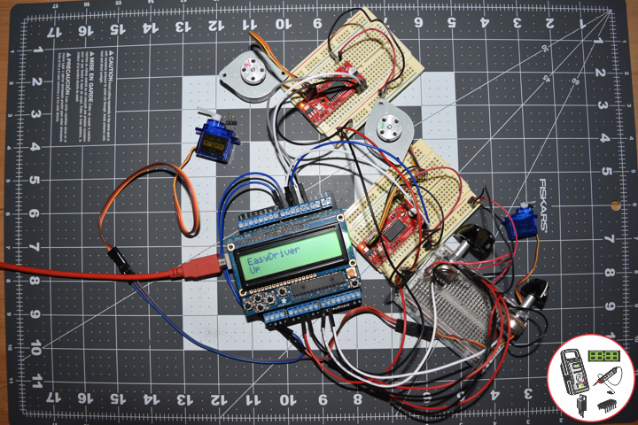
// isStepper1
void isStepper1(){
// set the cursor to column 0, line 0
RGBLCDShield.setCursor(0,0);
RGBLCDShield.print("EasyDriver"); // EasyDriver
RGBLCDShield.setCursor(0,1);
RGBLCDShield.print("Small Stepper"); // Small Stepper
delay(500);
// EasyDriver
digitalWrite(dirPinR, LOW); // Set the direction.
delay(100);
for (i = 0; i<300; i++) // Iterate for 1000 microsteps.
{
digitalWrite(stepPinR, LOW); // This LOW to HIGH change is what creates the
digitalWrite(stepPinR, HIGH); // "Rising Edge" so the easydriver knows to when to step.
delayMicroseconds(170); // This delay time is close to top speed.
}
}
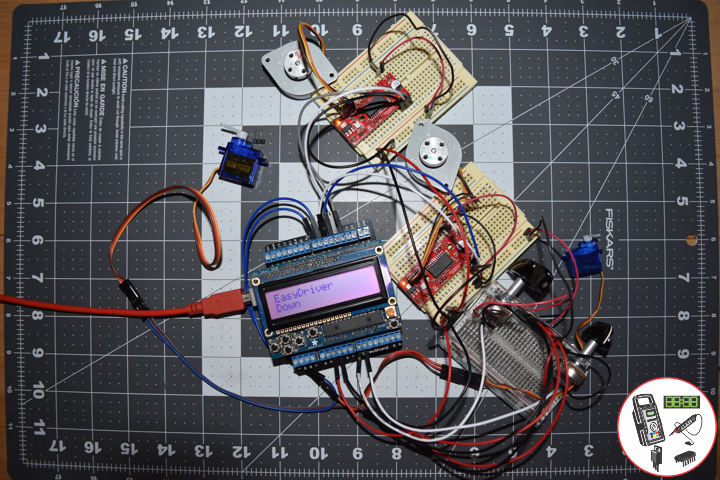
// isStepper2
void isStepper2(){
// set the cursor to column 0, line 0
RGBLCDShield.setCursor(0,0);
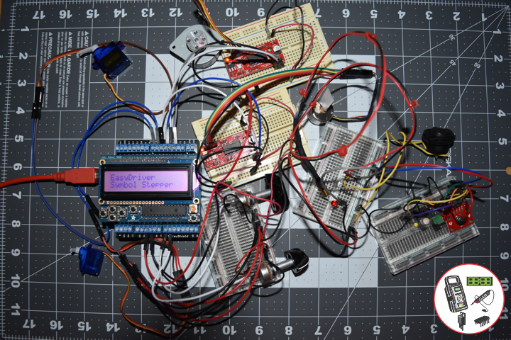
RGBLCDShield.print("EasyDriver"); // EasyDriver
RGBLCDShield.setCursor(0,1);
RGBLCDShield.print("Symbol Stepper"); // Symbol Stepper
delay(500);
// EasyDriver
digitalWrite(dirPinL, HIGH); // Set the direction.
delay(100);
for (i = 0; i<300; i++) // Iterate for 1000 microsteps.
{
digitalWrite(stepPinL, LOW); // This LOW to HIGH change is what creates the
digitalWrite(stepPinL, HIGH); // "Rising Edge" so the easydriver knows to when to step.
delayMicroseconds(170); // This delay time is close to top speed.
}
}
// isStepperStop
void isStepperStop() {
// 2 x EasyDriver
digitalWrite(dirPinR, LOW); // Set the direction.
delay(100);
digitalWrite(dirPinL, LOW); // Set the direction.
delay(100);
digitalWrite(stepPinR, LOW); // This LOW to HIGH change is what creates the
digitalWrite(stepPinL, LOW); // This LOW to HIGH change is what creates the
}
getSwitch.ino
// Switch
// Switch 1
void isSwitch1(){
// Small Stepper
yy = 1;
// EasyDriver
isStepper1();
}
// Switch 2
void isSwitch2(){
// Symbol Stepper
yy = 2;
// EasyDriver
isStepper2();
}
// Switch 3
void isSwitch3(){
// RC Servo Motor 1
yy = 3;
// Potentiometer RC Servo Motor 1
isServo1();
}
// Switch 4
void isSwitch4(){
// RC Servo Motor 2
yy = 4;
// Potentiometer RC Servo Motor 2
isServo2();
}
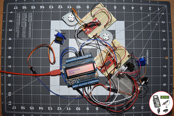
// Switch 5
void isSwitch5(){
// Stop
yy = 5;
// set the cursor to column 0, line 0
RGBLCDShield.setCursor(0,0);
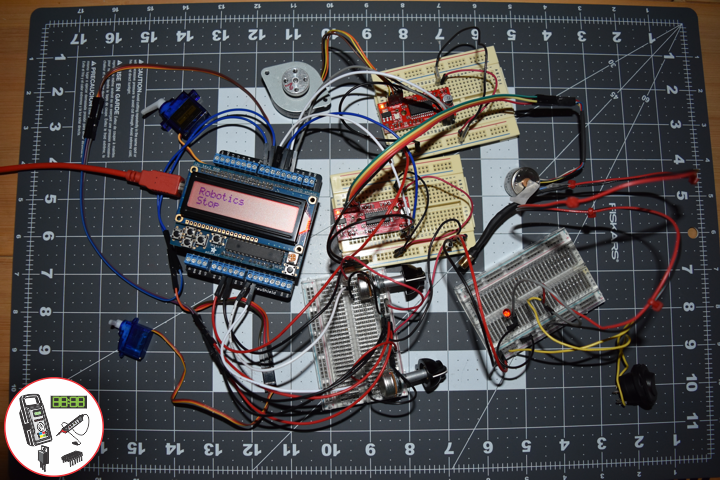
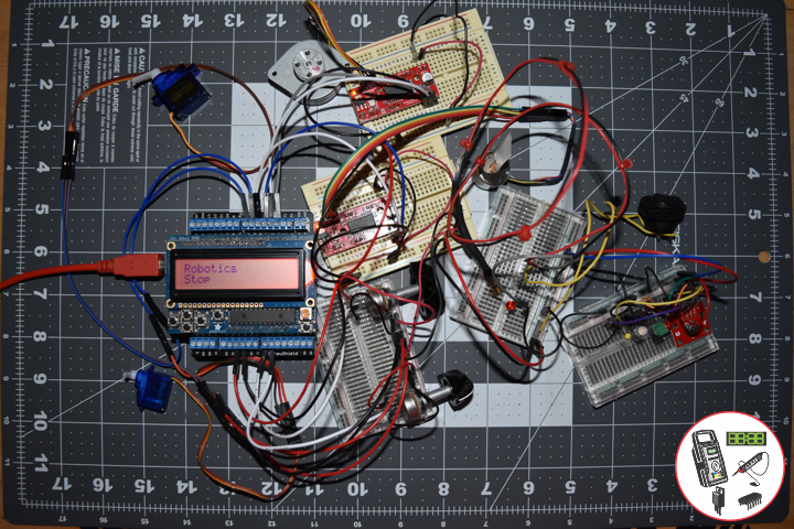
RGBLCDShield.print("Robotics"); // Robotics
RGBLCDShield.setCursor(0,1);
RGBLCDShield.print("Stop");
delay( 500 );
// EasyDriver
isStepperStop();
}
setup.ino
// Setup
void setup() {

  // Adafruit RGB LCD Shield
  // Set up the LCD's number of columns and rows:
  RGBLCDShield.begin(16, 2);
  RGBLCDShield.setBacklight(GREEN);

  // Display
  // Set the cursor to column 0, line 0
  RGBLCDShield.setCursor(0,0);
  RGBLCDShield.print("Don Luc Electron");         // Don luc Electron
  // Set the cursor to column 0, line 1
  RGBLCDShield.setCursor(0, 1);
  RGBLCDShield.print("Robotics");                // EasyDriver

  delay(5000);

  // Clear
  RGBLCDShield.clear();

  // 2 x EasyDriver
  isStepperSetup();

  // 2 x RC Servo Motor
  isServoSetup();

}
Follow Us
Web: https://www.donluc.com/
Web: http://www.jlpconsultants.com/
Web: https://www.donluc.com/DLHackster/
Web: https://www.hackster.io/neosteam-labs
Web: http://neosteamlabs.com/
YouTube: https://www.youtube.com/channel/UC5eRjrGn1CqkkGfZy0jxEdA
Facebook: https://www.facebook.com/neosteam.labs.9/
Instagram: https://www.instagram.com/neosteamlabs/
Pinterest: https://www.pinterest.com/NeoSteamLabs/
Twitter: https://twitter.com/labs_steam
Etsy: https://www.etsy.com/shop/NeoSteamLabs
Don Luc