——
——
——
——
#donluc #meditation #glassesmeditation #glassesledmeditation #neopixels #audioplayer #microsd #arduino #sparkfun #project #programming #electronics #microcontrollers #consultant #patreon #videoblog
TMRpcm
PCM(Pulse Width Modulation)/WAV playback direct from SD card
Samples Per second(Hz): 16000
Main formats: WAV files, 8-bit, 8-32khz Sample Rate, mono.
Voice: Yes
Music: No / Yes
Qwiic MP3 Trigger
The Qwiic MP3 Trigger is designed to operate at 3.3V and must not be powered above 3.6V as this is the maximum operating voltage of microSD cards. Otherwise, the board can also be powered through the Qwiic connector.
MP3 and ATtiny84
At the heart of the Qwiic MP3 Trigger is the WT2003S MP3 decoder IC. This IC reads MP3s from the microSD card and will automatically mount the SD card as a jump drive if USB is detected. The ATtiny84A receives I2C commands and controls the MP3 decoder.
Audio Amplifier
The speaker is boosted by a Class-D mono amplifier capable of outputting up to 1.4W. Both outputs have volume controlled by the SET_VOLUME command and is selectable between 32 levels.
Audio Outputs
This is a friction fit type connector; simply push stranded core wire into the hole and the connector will grip the wire, speaker as Dayton audio reference 3″ full-range drive.
Voice: Yes
Music: Yes
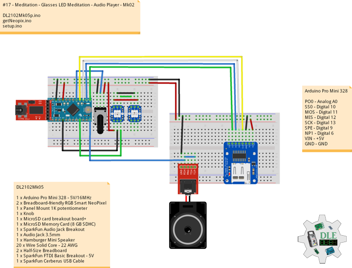
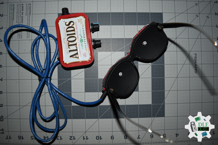
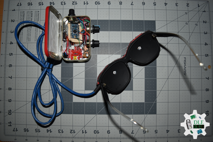
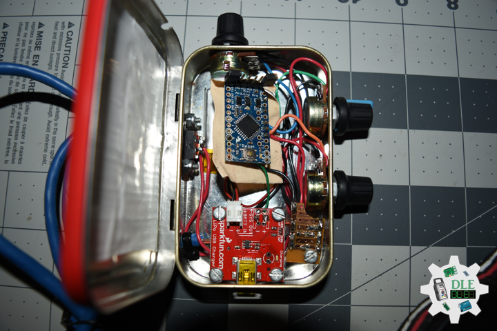
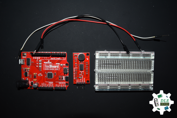
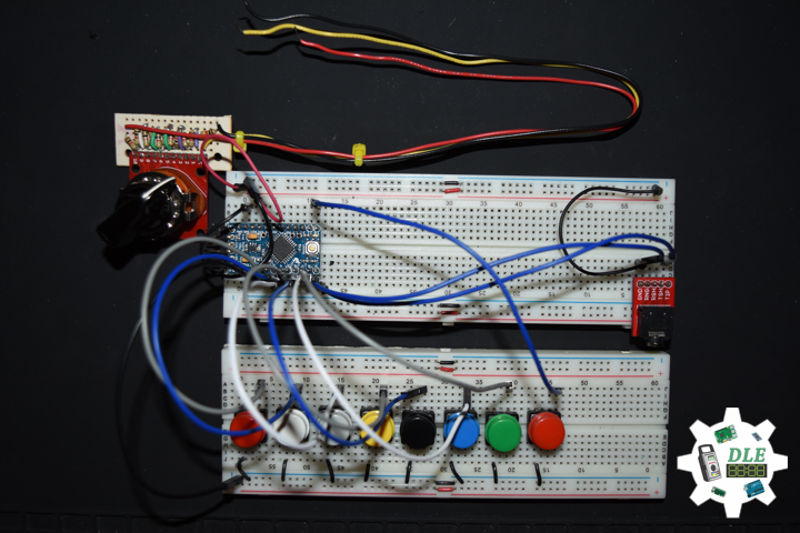
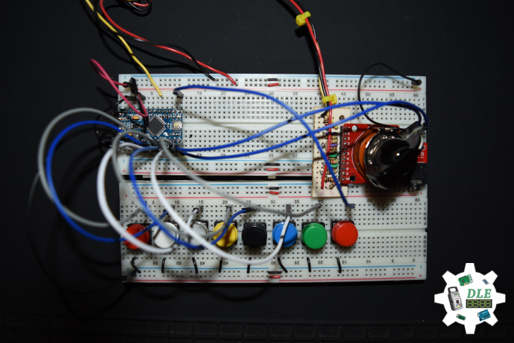
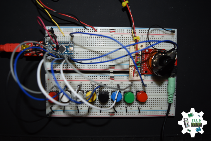
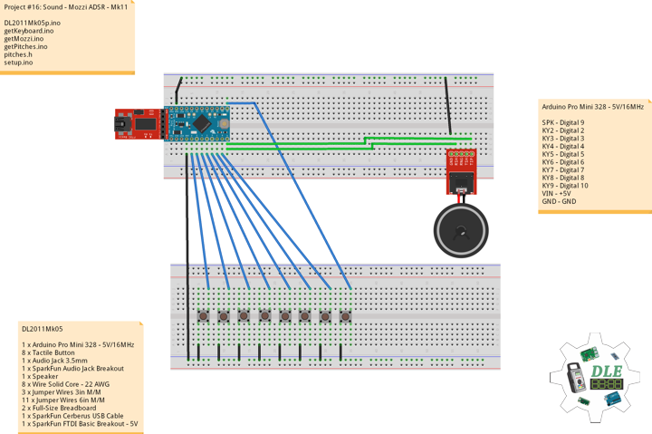
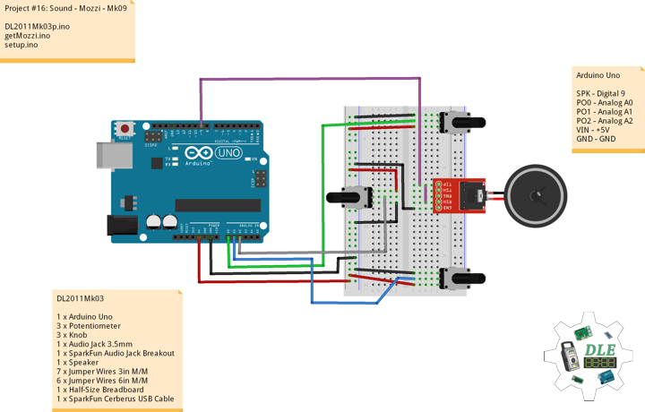
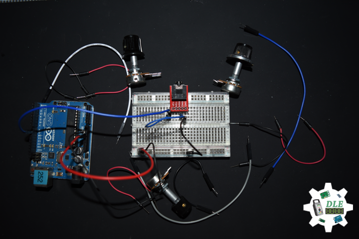
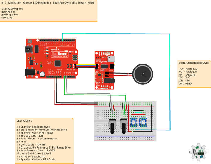
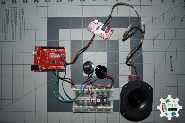
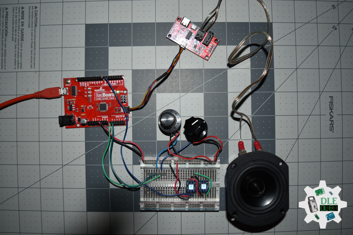
DL2102Mk06
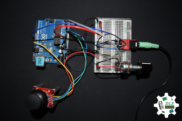
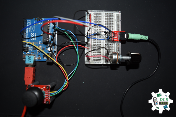
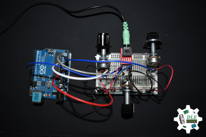
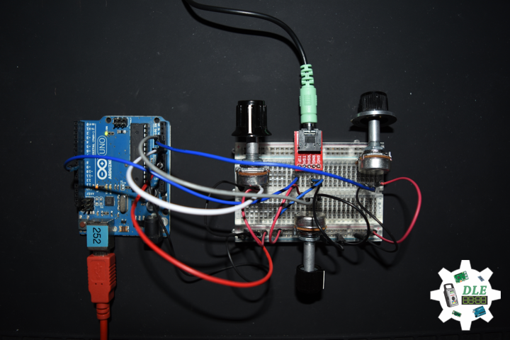
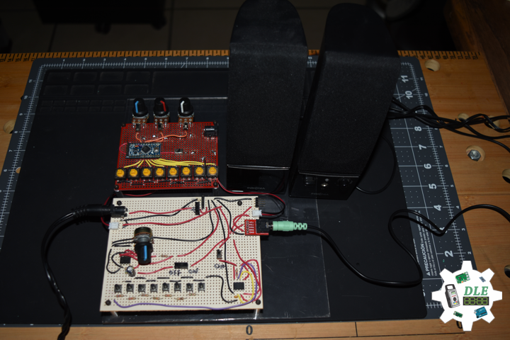
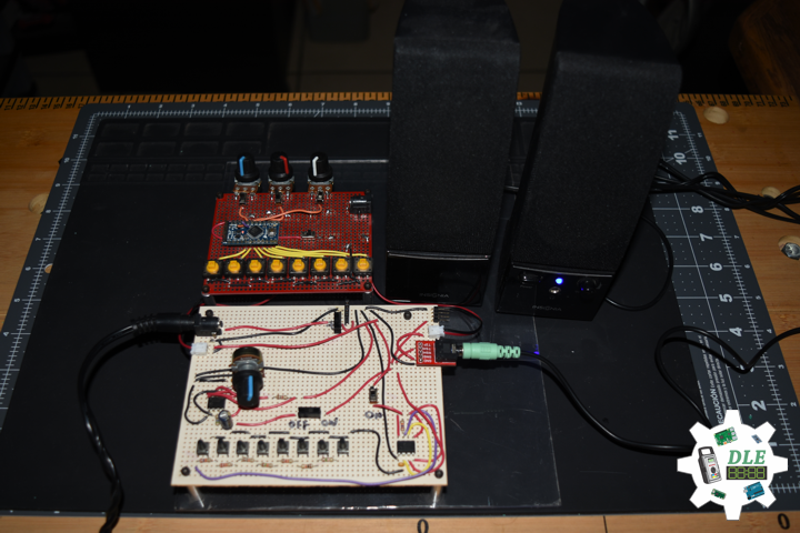
1 x SparkFun RedBoard Qwiic
2 x Breadboard-friendly RGB Smart NeoPixel
1 x SparkFun Qwiic MP3 Trigger
1 x microSD Card – 2GB
2 x Panel Mount 1K potentiometer
2 x Knob
1 x Qwiic Cable – 100mm
1 x Dayton Audio Reference 3″ Full-Range Drive
2 x Wire Stranded Core – 18 AWG
17 x Wire Solid Core – 22 AWG
1 x Half-Size Breadboard
1 x SparkFun Cerberus USB Cable
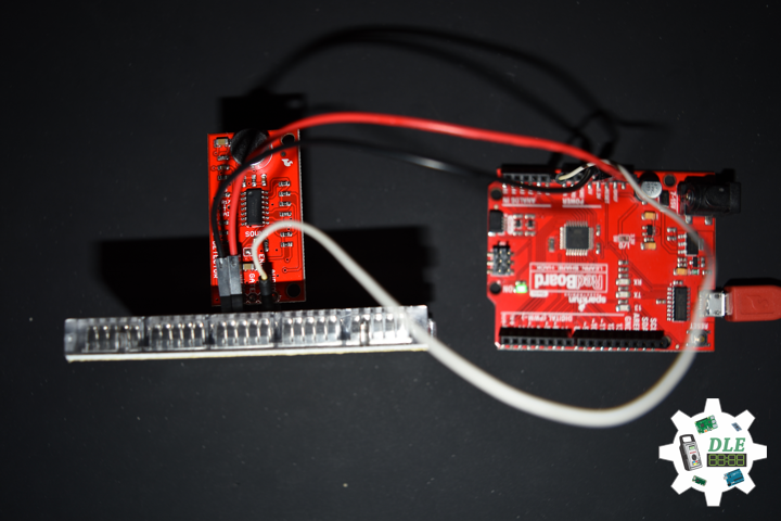
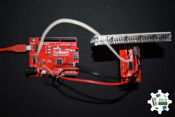
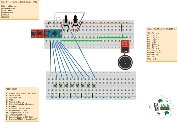
SparkFun RedBoard Qwiic
PO0 – Analog A0
PO1 – Analog A1
NP1 – Digital 6
I2C – 0x37
VIN – +5V
GND – GND
DL2102Mk06p.ino
// ***** Don Luc Electronics © *****
// Software Version Information
// #17 - Meditation - Glasses LED Meditation - SparkFun Qwiic MP3 Trigger - Mk03
// 02-06
// DL2102Mk06p.ino 17-03
// 1 x Arduino Pro Mini 328 - 5V/16MHz
// 2 x Breadboard-friendly RGB Smart NeoPixel
// 1 x SparkFun Qwiic MP3 Trigger
// 1 x microSD Card - 2GB
// 2 x Panel Mount 1K potentiometer
// 2 x Knob
// 1 x Qwiic Cable - 100mm
// 1 x Dayton Audio Reference 3" Full-Range Drive
// 2 x Wire Stranded Core - 16 AWG
// 17 x Wire Solid Core - 22 AWG
// 1 x Half-Size Breadboard
// 1 x SparkFun Cerberus USB Cable

// Include the Library Code
// NeoPixel
#include <Adafruit_NeoPixel.h>
// Wire communicate with I2C / TWI devices
#include <Wire.h>
// SparkFun MP3 Trigger
#include "SparkFun_Qwiic_MP3_Trigger_Arduino_Library.h"

// NeoPixels
#define PIN 6
// How many NeoPixels are attached to the Arduino
#define NUMPIXELS 2
Adafruit_NeoPixel pixels = Adafruit_NeoPixel(NUMPIXELS, PIN, NEO_GRB + NEO_KHZ800);
// Color
// Red
int red = 0;
// Green
int green = 0;
// Blue
int blue = 0;
// Panel Mount 1K potentiometer
// Brighten
const int iSensorBrighten = A0;
// Max - Min
int BrightenValue = 0;
// Minimum sensor value
int BrightenMin = 0;
// Maximum sensor value
int BrightenMax = 1023;
// Color
const int iSensorColor = A1;
int y = 0;
int ColorVal = 0;

// SparkFun MP3 Trigger
MP3TRIGGER mp3;

// Software Version Information
String sver = "17-03";

void loop() {

  // Range Color
  isRangeColor();

  if (mp3.isPlaying() == false) {

    // Play Track dleMk002.mp3
    mp3.playTrack(1);

  }

}
getMP3.ino
// MP3
// Setup MP3
void isSetupMP3(){

  // Check to see if Qwiic MP3 is present on the bus
  if (mp3.begin() == false)
  {
    // Qwiic MP3 failed to respond. Please check wiring and possibly the I2C address. Freezing...
    while (1);
  }

  if (mp3.hasCard() == false)
  {
    // Qwiic MP3 is missing its SD card. Freezing...
    while (1);
  }

  // Volume can be 0 (off) to 31 (max)
  mp3.setVolume(28);

  // Play Track dleMk002.mp3
  mp3.playTrack(1);

}
getNeopix.ino
// Neopix
void isNeopix() {

  for(int i=0; i<NUMPIXELS; i++){

    // Neopix
    // Read the Brightneed
    BrightenValue = analogRead( iSensorBrighten );

    // Apply the calibration to the BrightneedValue reading
    BrightenValue = map(BrightenValue, BrightenMin, BrightenMax, 0, 255);

    // In case the sensor value is outside the range seen during calibration
    BrightenValue = constrain(BrightenValue, 0, 255);

    // The pixels.Color takes RGB values, from 0,0,0 up to 255,255,255
    pixels.setBrightness( BrightenValue );
    pixels.setPixelColor(i, pixels.Color(red,green,blue));
    // This sends the updated pixel color to the hardware
    pixels.show();

  }

}
// Range Color
void isRangeColor() {

  // Range Color
  ColorVal = analogRead( iSensorColor );
  y = (ColorVal / 127);

  switch (y) {
    case  0:
      // Blue
      red = 0;
      green = 102;
      blue = 204;
      isNeopix();
      break;
    case 1:
      // Yellow
      red = 255;
      green = 255;
      blue = 0;
      isNeopix();
      break;
    case 2:
      // Pink
      red = 255;
      green = 153;
      blue = 203;
      isNeopix();
      break;
    case 3:
      // White
      red = 255;
      green = 255;
      blue = 255;
      isNeopix();
      break;
    case 4:
      // Green
      red = 0;
      green = 255;
      blue = 0;
      isNeopix();
      break;
    case 5:
      // Orange
      red = 255;
      green = 102;
      blue = 0;
      isNeopix();
      break;
    case 6:
      // Violet
      red = 204;
      green = 102;
      blue = 204;
      isNeopix();
      break;
    case 7:
      // Red
      red = 255;
      green = 0;
      blue = 0;
      isNeopix();
      break;
  }

}
setup.ino
// Setup
void setup() {

   // This initializes the NeoPixel library
   pixels.begin();

   // Serial
   // Serial.begin(9600);

   // Wire communicate with I2C / TWI devices
   Wire.begin();

   // SparkFun MP3 Trigger Setup
   isSetupMP3();

}
Music
dleMk002.mp3
People can contact us: https://www.donluc.com/?page_id=1927
Technology Experience
- Single-Board Microcontrollers (PIC, Arduino, Raspberry Pi,Espressif, etc…)
- Robotics
- Research & Development (R & D)
- Desktop Applications (Windows, OSX, Linux, Multi-OS, Multi-Tier, etc…)
- Mobile Applications (Android, iOS, Blackberry, Windows Mobile, Windows CE, etc…)
- Web Applications (LAMP, Scripting, Java, ASP, ASP.NET, RoR, Wakanda, etc…)
- Social Media Programming & Integration (Facebook, Twitter, YouTube, Pinterest, etc…)
- Content Management Systems (WordPress, Drupal, Joomla, Moodle, etc…)
- Bulletin Boards (phpBB, SMF, Vanilla, jobberBase, etc…)
- eCommerce (WooCommerce, OSCommerce, ZenCart, PayPal Shopping Cart, etc…)
Instructor
- PIC Microcontrollers
- Arduino
- Raspberry Pi
- Espressif
- Robotics
- DOS, Windows, OSX, Linux, iOS, Android, Multi-OS
- Linux-Apache-PHP-MySQL
Follow Us
J. Luc Paquin – Curriculum Vitae
https://www.donluc.com/DLE/LucPaquinCVEngMk2021a.pdf
Web: https://www.donluc.com/
Web: http://www.jlpconsultants.com/
Web: https://www.donluc.com/DLE/
Web: https://www.donluc.com/DLHackster/
Web: https://www.hackster.io/neosteam-labs
Patreon: https://www.patreon.com/DonLucElectronics
Facebook: https://www.facebook.com/neosteam.labs.9/
YouTube: https://www.youtube.com/channel/UC5eRjrGn1CqkkGfZy0jxEdA
Twitter: https://twitter.com/labs_steam
Pinterest: https://www.pinterest.com/NeoSteamLabs/
Instagram: https://www.instagram.com/neosteamlabs/
Don Luc