——
——
——
——
——
——
——
EEPROM
EEPROM stands for electrically erasable programmable read-only memory and is a type of non-volatile memory used in computers, integrated in microcontrollers for smart cards and remote keyless systems, and other electronic devices to store relatively small amounts of data but allowing individual bytes to be erased and reprogrammed.
Transmitter
In electronics and telecommunications a transmitter or radio transmitter is an electronic device which produces radio waves with an antenna. The transmitter itself generates a radio frequency alternating current, which is applied to the antenna. When excited by this alternating current, the antenna radiates radio waves.
Receiver
A modern communications receiver, used in two-way radio communication stations to talk with remote locations by shortwave radio.
In radio communications, a radio receiver, also known as a receiver, wireless or simply radio is an electronic device that receives radio waves and converts the information carried by them to a usable form. It is used with an antenna. The antenna intercepts radio waves (electromagnetic waves) and converts them to tiny alternating currents which are applied to the receiver, and the receiver extracts the desired information.
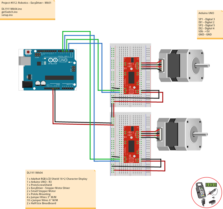
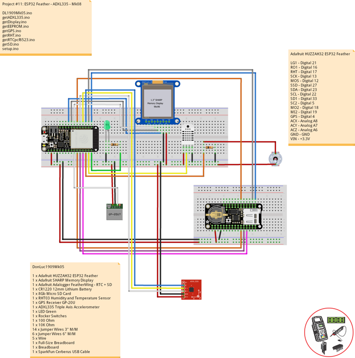
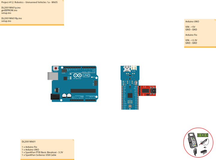
DL2001Mk01
1 x Arduino Fio
1 x Arduino UNO
1 x SparkFun FTDI Basic Breakout – 3.3V
1 x SparkFun Cerberus USB Cable
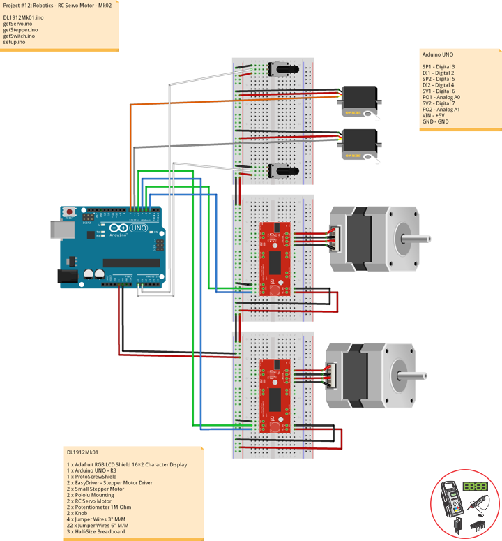
Arduino UNO
VIN – +5V
GND – GND
Arduino Fio
VIN – +3.3V
GND – GND
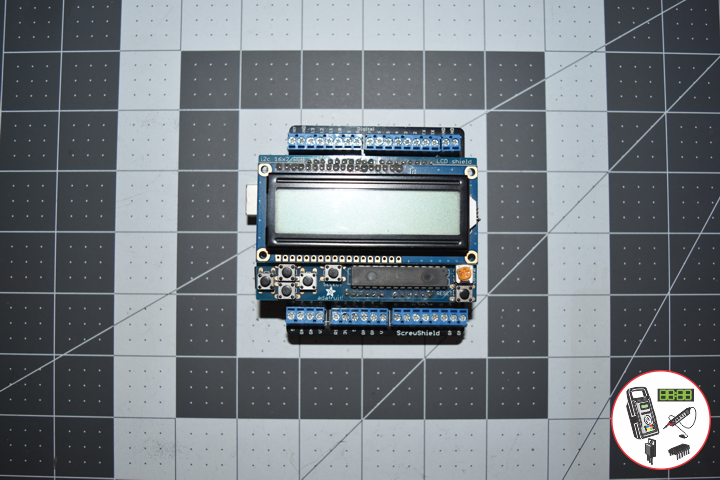
Transmitter => DT001
DL2001Mk01p.ino
// ***** Don Luc Electronics © *****
// Software Version Information
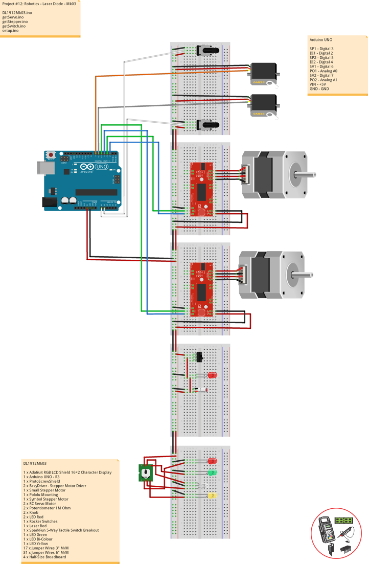
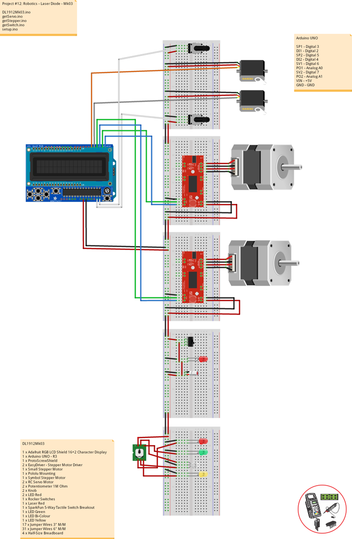
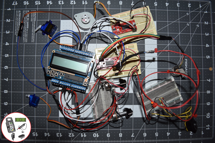
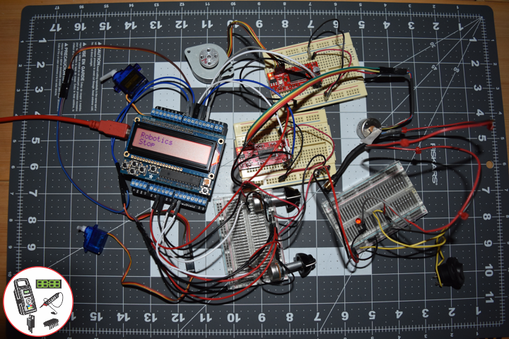
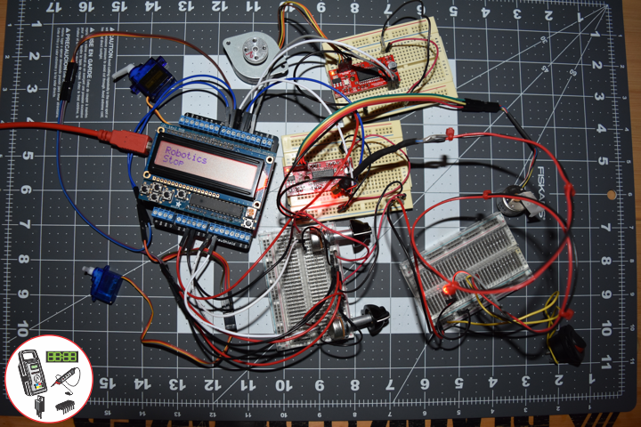
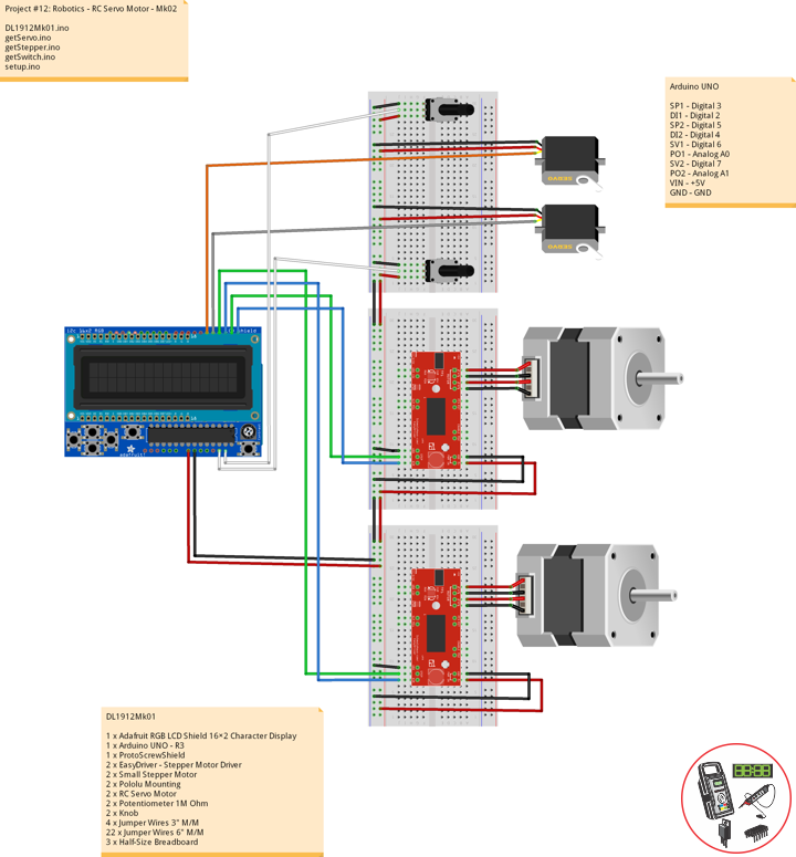
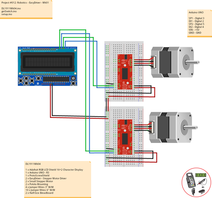
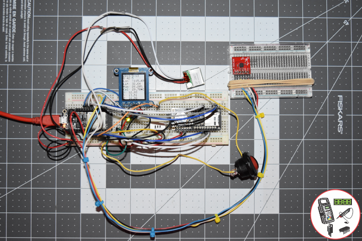
// Project #12: Robotics - Unmanned Vehicles 1a - Mk05
// 01-01
// DL2001Mk01p.ino 12-05
// Arduino UNO
// Screw Shield
// Adafruit RGB LCD Shield
// EEPROM with Unique ID
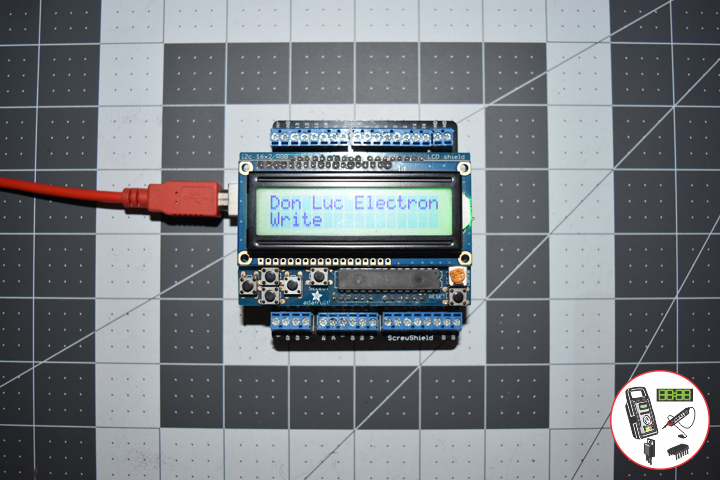
// Transmitter
// Include the library code:
#include <Adafruit_RGBLCDShield.h>
// EEPROM library to read and write EEPROM with unique ID for unit
#include <EEPROM.h>
// Adafruit RGB LCD Shield
Adafruit_RGBLCDShield RGBLCDShield = Adafruit_RGBLCDShield();
// These #defines make it easy to set the backlight color
#define GREEN 0x2
// Momentary Button
int yy = 0;
uint8_t momentaryButton = 0;
// Software Version Information
String sver = "12-05";
// Unit ID Information
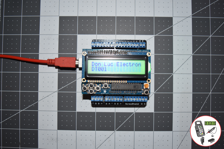
String uid = "DT001";
void loop() {
// Display
// Set the cursor to column 0, line 0
RGBLCDShield.setCursor(0,0);
RGBLCDShield.print("Don Luc Electron"); // Don luc Electron
momentaryButton = RGBLCDShield.readButtons();
if ( momentaryButton ) {
if ( momentaryButton & BUTTON_UP ) {
isEEPROMw();
yy = 1;
}
if ( momentaryButton & BUTTON_DOWN ) {
isUID();
yy = 2;
}
if ( momentaryButton & BUTTON_LEFT ) {
UIDr();
yy =3;
}
if ( momentaryButton & BUTTON_RIGHT ) {
isEEPROMc();
yy = 4;
}
}
delay(1000);
// Clear
RGBLCDShield.clear();
}
getEEPROM.ino
// getEEPROM
// Write and Read EEPROM with Unique ID for Unit
// Write EEPROM with Unique ID for Unit
void isEEPROMw() {

  // set the cursor to column 0, line 1
  RGBLCDShield.setCursor(0, 1);
  RGBLCDShield.print( "Write" );

  // EEPROM
  int incb = 0;
  int v = 0;
  String msg = "";
  String emp = "";

  // Set Unit ID
  // The message starts with sid then is followed by 5 characters
  // First clear a string buffer
  emp = "";
  // Loop through the 5 ID characters and write their ASCII (byte) value to the EEPROM
  for (int x = 0; x < 5; x++)
    {
       //Get ASCII value of character
       v = int(uid.charAt(x)); // + 5));
       //Add the actual character to the buffer so we can send it back to the PC
       emp = emp + uid.charAt(x + 5);
       //Write the value to the EEPROM
       EEPROM.write(x, v);
    }

   delay( 5000 );

}
// Read EEPROM with Unique ID for Unit
void isUID()
{
  // Unit ID
  String ruid = "";
  for (int x = 0; x < 5; x++)
  {
    ruid = ruid + char(EEPROM.read(x));
  }

  // set the cursor to column 0, line 1
  RGBLCDShield.setCursor(0, 1);
  RGBLCDShield.print( ruid );

  delay( 5000 );

}
// Read uid
void UIDr()
{

   // set the cursor to column 0, line 1
   RGBLCDShield.setCursor(0, 1);
   RGBLCDShield.print( uid );

   delay( 5000 );

}
// Clear EEPROM
void isEEPROMc()
{

   // Clear EEPROM
   for (int i = 0 ; i < EEPROM.length() ; i++) {
      EEPROM.write(i, 0);
   }

   // set the cursor to column 0, line 1
   RGBLCDShield.setCursor(0, 1);
   RGBLCDShield.print( "Clear EEPROM" );

   delay( 5000 );

}
setup.ino
// Setup
void setup() {

  // Adafruit RGB LCD Shield
  // Set up the LCD's number of columns and rows:
  RGBLCDShield.begin(16, 2);
  RGBLCDShield.setBacklight(GREEN);

  // Display
  // Set the cursor to column 0, line 0
  RGBLCDShield.setCursor(0,0);
  RGBLCDShield.print("Don Luc Electron");         // Don luc Electron
  // Set the cursor to column 0, line 1
  RGBLCDShield.setCursor(0, 1);
  RGBLCDShield.print("Unique ID");                // Unique ID

  delay(5000);

  // Clear
  RGBLCDShield.clear();

}
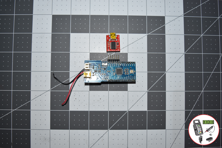
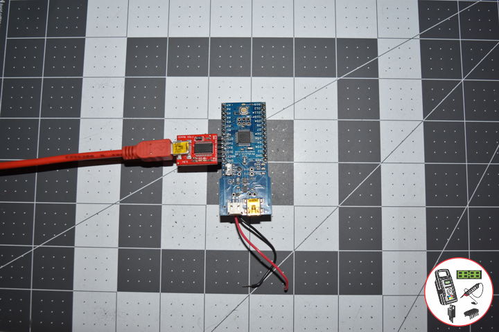
Receiver => DR001
DL2001Mk01Rp.ino
// ***** Don Luc Electronics © *****
// Software Version Information
// Project #12: Robotics - Unmanned Vehicles 1a - Mk05
// 01-01
// DL2001Mk01Rp.ino 12-05
// Arduino Fio
// SparkFun FTDI Basic Breakout - 3.3V
// EEPROM with Unique ID
// Receiver

// Include the library code:
// EEPROM library to read and write EEPROM with unique ID for unit
#include <EEPROM.h>

// Software Version Information
String sver = "12-05";
// Unit ID information
String uid = "DR001";

void loop() {

  // Write EEPROM with Unique ID for Unit
  int incb = 0;
  int v = 0;
  String emp = "";
  String ruid = "";

  // Set Unit ID
  // The message starts with uid then is followed by 5 characters
  // First clear a string buffer
  emp = "";
  // Loop through the 5 ID characters and write their ASCII (byte) value to the EEPROM
  for (int y = 0; y < 5; y++)
  {

     // Get ASCII value of character
     v = int(uid.charAt(y)); // + 5));
     // Add the actual character to the buffer
     emp = emp + uid.charAt(y + 5);
     // Write the value to the EEPROM
     EEPROM.write(y, v);

  }

  // Write EEPROM with Unique ID for Unit
  Serial.println( "Write ID Information");

  // Read ID Information
  // Unit ID
  for (int y = 0; y < 5; y++)
  {

    ruid = ruid + char(EEPROM.read(y));

  }

  // Read ID Information
  Serial.print( "Read ID Information: ");
  Serial.println( ruid );
  Serial.println( "Ok!" );
  ruid = "";

  delay( 5000 );

}
setup.ino
// Setup
void setup() {

  // Open the serial port at 9600 bps:
  Serial.begin(9600);

  // Serial
  Serial.print( "Software Version Information: ");
  Serial.println( sver );
  Serial.print( "Unit ID Information: ");
  Serial.println( uid );

  delay(5000);

}
Follow Us
J. Luc Paquin – Curriculum Vitae
https://www.donluc.com/DLHackster/LucPaquinCVEngMk2020a.pdf
Web: https://www.donluc.com/
Web: http://www.jlpconsultants.com/
Web: https://www.donluc.com/DLHackster/
Web: https://www.hackster.io/neosteam-labs
Web: http://neosteamlabs.com/
YouTube: https://www.youtube.com/channel/UC5eRjrGn1CqkkGfZy0jxEdA
Facebook: https://www.facebook.com/neosteam.labs.9/
Instagram: https://www.instagram.com/neosteamlabs/
Pinterest: https://www.pinterest.com/NeoSteamLabs/
Twitter: https://twitter.com/labs_steam
Etsy: https://www.etsy.com/shop/NeoSteamLabs
Don Luc