
Stepper Motor
A stepper motor or step motor or stepping motor is a brushless DC electric motor that divides a full rotation into a number of equal steps. The motor’s position can then be commanded to move and hold at one of these steps without any position sensor for feedback (an open-loop controller), as long as the motor is carefully sized to the application in respect to torque and speed.
Switched reluctance motors are very large stepping motors with a reduced pole count, and generally are closed-loop commutated.
Fundamentals of Operation
Brushed DC motors rotate continuously when DC voltage is applied to their terminals. The stepper motor is known by its property to convert a train of input pulses (typically square wave pulses) into a precisely defined increment in the shaft position. Each pulse moves the shaft through a fixed angle.
Stepper motors effectively have multiple “toothed” electromagnets arranged around a central gear-shaped piece of iron. The electromagnets are energized by an external driver circuit or a micro controller. To make the motor shaft turn, first, one electromagnet is given power, which magnetically attracts the gear’s teeth. When the gear’s teeth are aligned to the first electromagnet, they are slightly offset from the next electromagnet. This means that when the next electromagnet is turned on and the first is turned off, the gear rotates slightly to align with the next one. From there the process is repeated. Each of those rotations is called a “step”, with an integer number of steps making a full rotation. In that way, the motor can be turned by a precise angle.
Unipolar Motors
A unipolar stepper motor has one winding with center tap per phase. Each section of windings is switched on for each direction of magnetic field. Since in this arrangement a magnetic pole can be reversed without switching the direction of current, the commutation circuit can be made very simple (e.g., a single transistor) for each winding. Typically, given a phase, the center tap of each winding is made common: giving three leads per phase and six leads for a typical two phase motor. Often, these two phase commons are internally joined, so the motor has only five leads.
Bipolar Motors
Bipolar motors have a single winding per phase. The current in a winding needs to be reversed in order to reverse a magnetic pole, so the driving circuit must be more complicated, typically with an H-bridge arrangement (however there are several off-the-shelf driver chips available to make this a simple affair). There are two leads per phase, none are common.
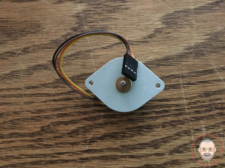
Small Stepper Motor
Description
These small steppers are a great way to get things moving, especially when positioning and repeatability is a concern.
When using a current limiting driver such as the Easydriver or Big Easydriver, a 12 volt power supply can be used as long as you adjust the current level to 400mA or less. If using a non current limited driver (like a L293D or an H-bridge) you will need to lower your input voltage to keep the motor current below 400mA.
This is a bipolar motor.
Features
* Stride Angle (degrees): 7.5
* 2-Phase
* Rated Voltage: 12V
* Rated Current: 400mA
* 3mm Diameter Drive Shaft
* 4-Wire Cable Attached
* In-traction Torque: 100 g/cm
Don Luc