SparkFun: PRT-09429
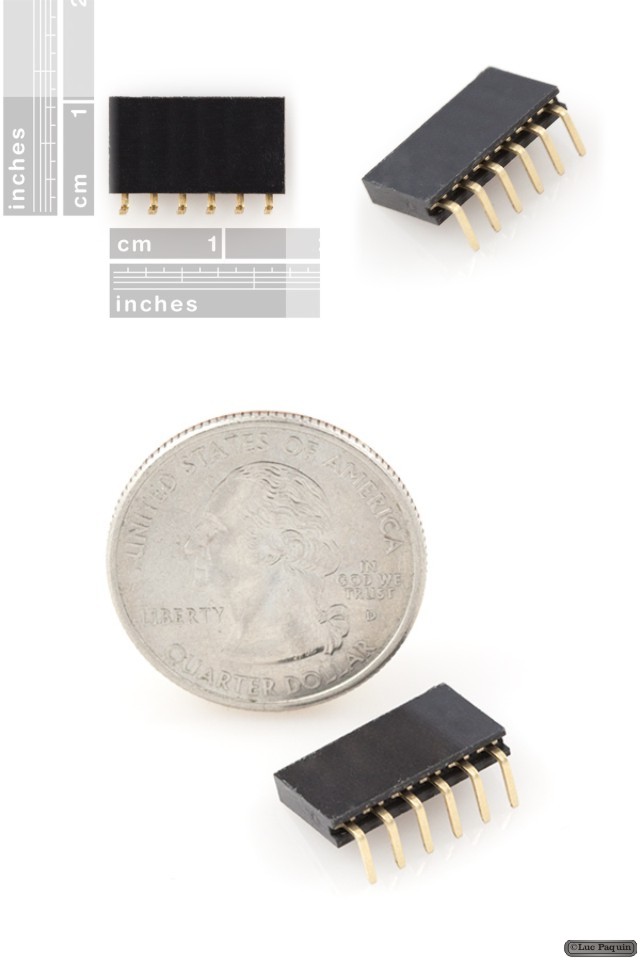
Description: This is a through-hole 6-pin right-angle female header. This header connects perfectly with the 6-pin male header on Arduino Pros and LilyPad Main Boards.
Pins are spaced by 0.1″.
Don Luc

The Alpha Geek – Geeking Out
SparkFun: PRT-09429
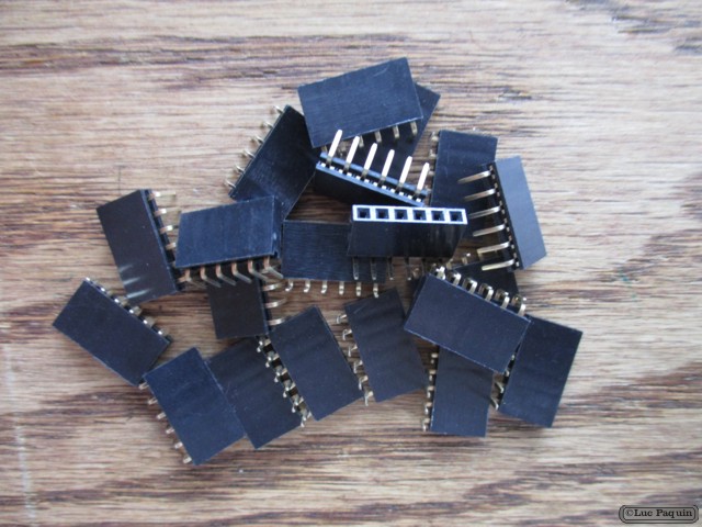
Description: This is a through-hole 6-pin right-angle female header. This header connects perfectly with the 6-pin male header on Arduino Pros and LilyPad Main Boards.
Pins are spaced by 0.1″.
Don Luc
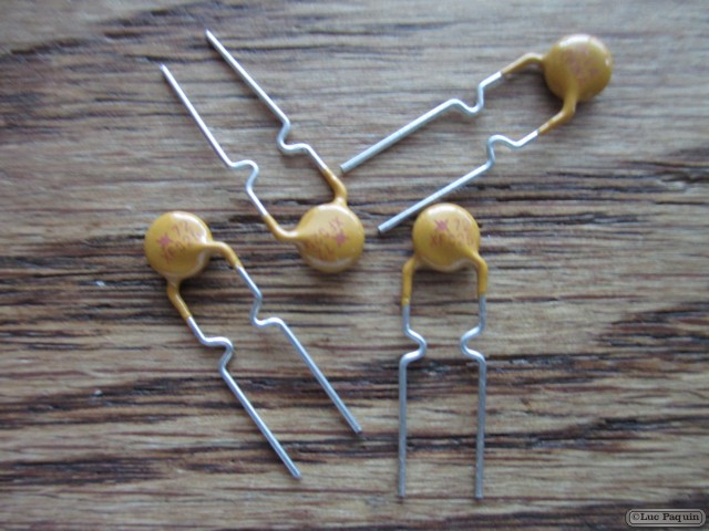
SparkFun: COM-08357
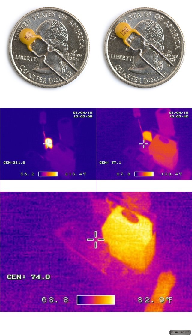
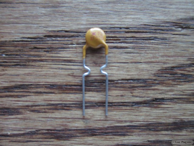
Description: This is a handy little device that can save your system from smoking. A resettable fuse (also known as a PTC) is a resistor that has very unique properties.
For this model, if your circuit tries to draw more than 250mA of current (if you have a bad short for instance) the PTC would ‘trip’ (by heating up). The increased resistance (trip state) would break the circuit and allow only a small leakage current.
The leakage current may still be enough to hurt some electronics but it’s much less than the 3A that the short may have allowed. Removing the short, the PTC ‘resets’ and allows current up to 250mA to flow again. It’s a resettable fuse that protects your system! Good for use on battery powered devices that need to protect again high-current accidental discharges.
The thermal pictures to the right do a great job of showing what happens when the PTC is tripped. The first thermal picture shows a voltage regulating circuit in its normal state. In the second picture the circuit is shorted, notice how hot the PTC gets (213 °F!) as it limits the amount of damaging current going through the circuit. Major thanks to Joshua Weaver for the great thermal shots!
Don Luc
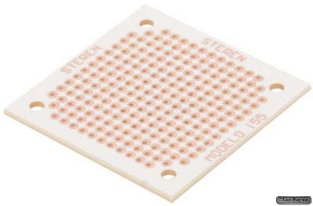
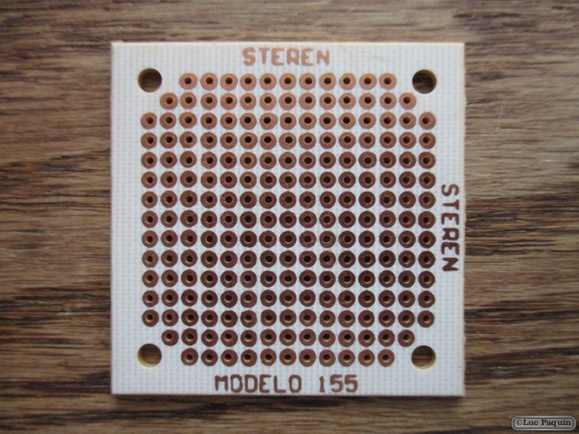
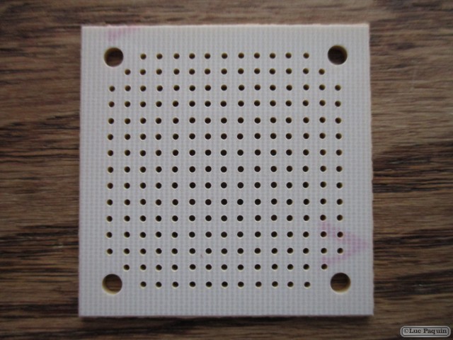
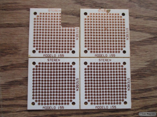
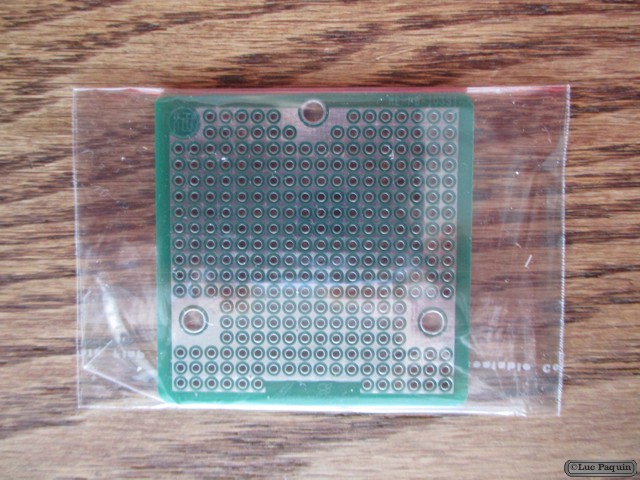
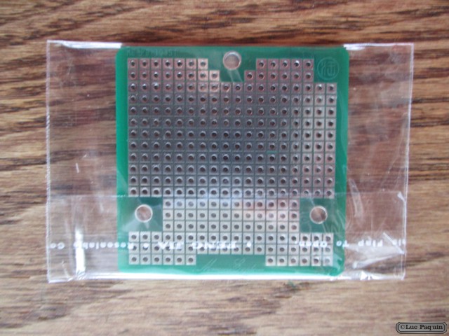
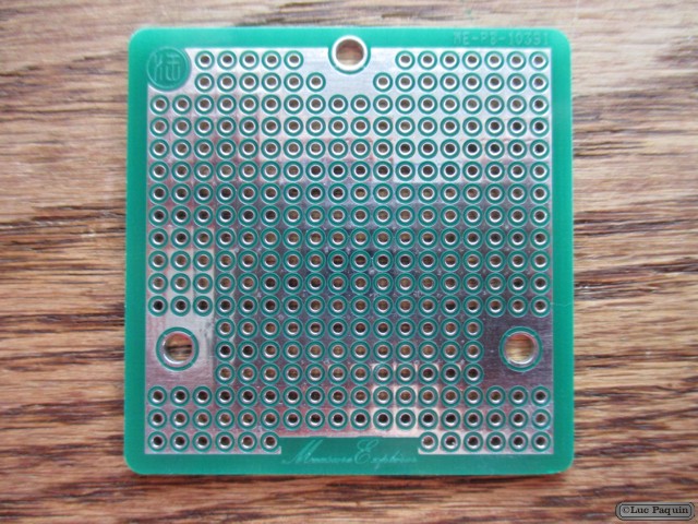
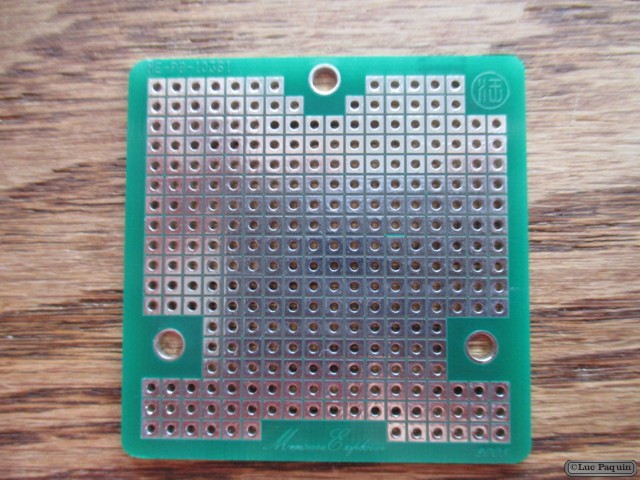
Steren: 155
Description: Bakelite phenolic copper plate of 4.5 x 4.5 cm, engraved and perforated with holes 164 and 4 components to fix the plate. Ideal for projects or prototypes.
Don Luc
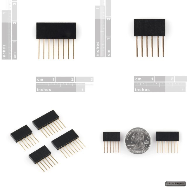
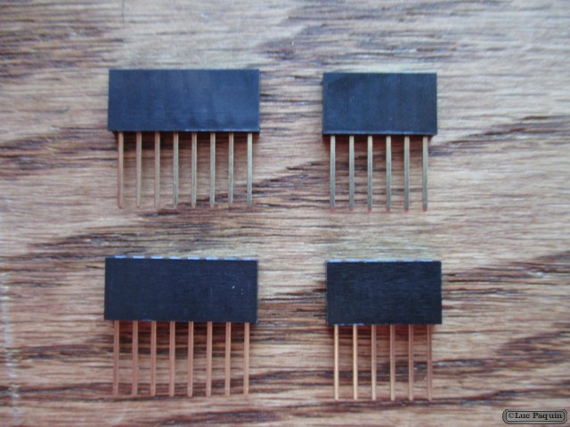
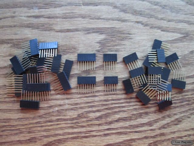
SparkFun: PRT-10007
Description: These headers are made to work with the Arduino Main Board, Arduino Pro, and the Arduino Mega. They are the perfect height for clearing the USB-B connector and great for stacking multiple shields. This kit includes 4 headers (2 8-pin and 2 6-pin), enough to connect a shield to an Arduino Main Board. These are the same headers we use in our tutorials and with our own shields.
Don Luc
SparkFun: PRT-09914
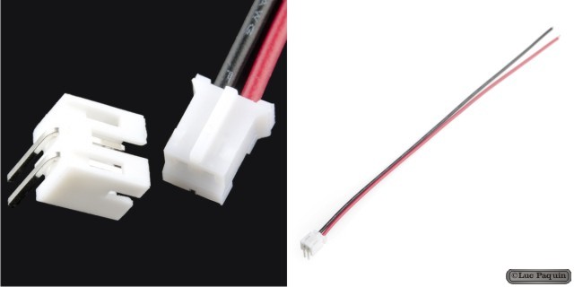
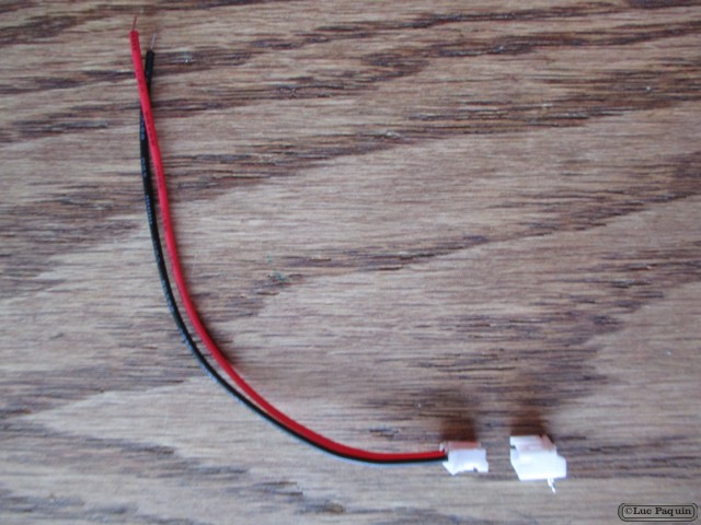
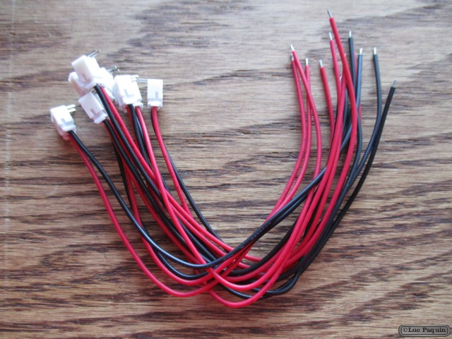
Description: This is a simple two wire cable. Great for jumping from board to board or just about anything else. There is a 2-pin JST connector on one end, bare cable on the opposite end. It also comes with the mating connector for the JST.
Dimensions: 6″ length
Don Luc
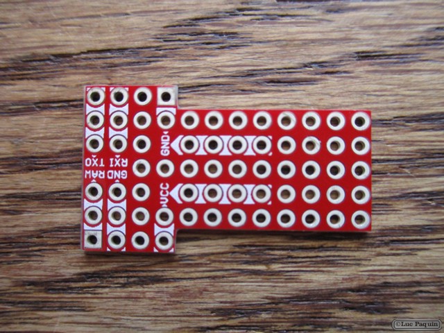
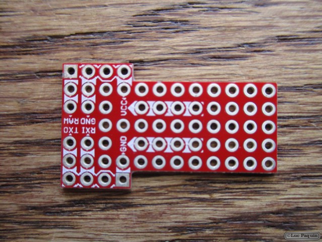
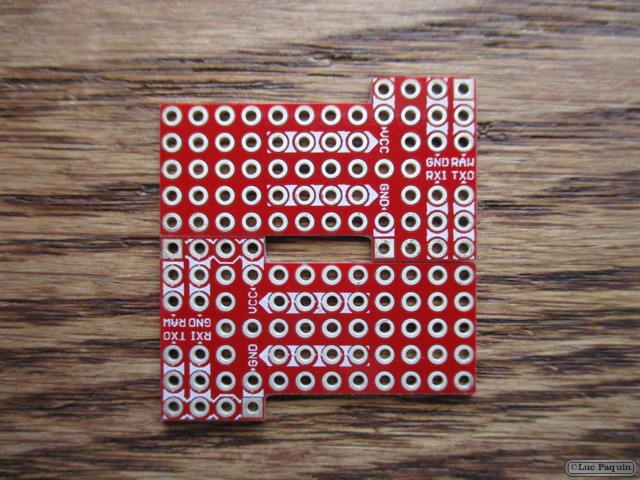
SparkFun: DEV-09709
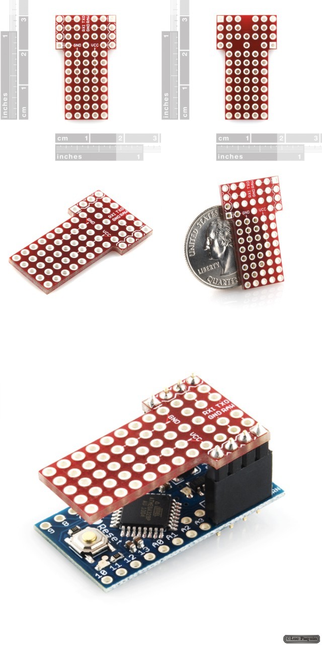
Description: This is a small prototyping shield for the Arduino Pro Mini. If your project requires just a little bit more space for your external circuitry, this might be a perfect addition. 38 unconnected PTHs are provided for your prototyping needs.
The shield fits the small form factor of the Arduino Pro Mini – connecting to the ‘top’ four pins on each side of the Mini (‘GND’-‘TXO’ & ‘VCC’-‘RAW’). There are small buses for VCC, GND and RAW. In addition to the power buses, the serial pins are also broken out on the shield. The analog and digital pins are not broken out on the shield.
Features:
Don Luc
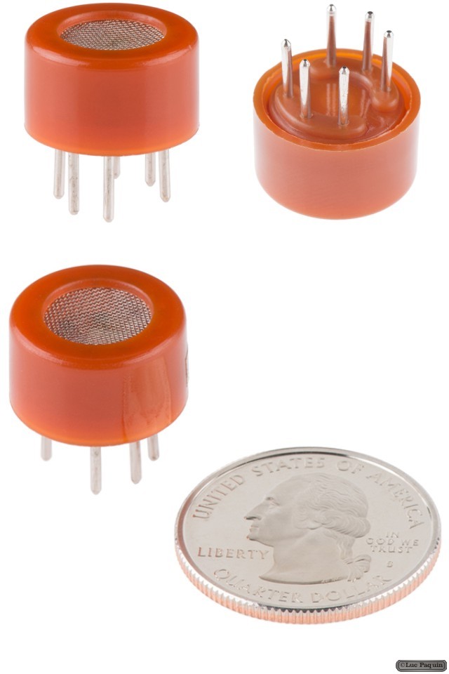
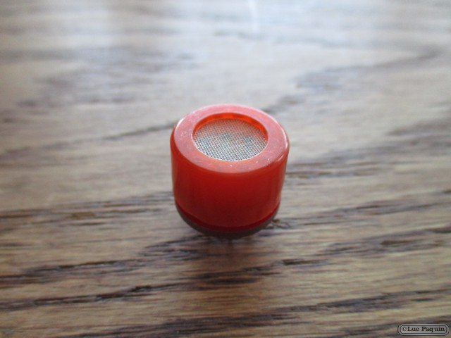
SparkFun: SEN-08880
Description: This alcohol sensor is suitable for detecting alcohol concentration on your breath, just like your common breathalyzer. It has a high sensitivity and fast response time. Sensor provides an analog resistive output based on alcohol concentration. The drive circuit is very simple, all it needs is one resistor. A simple interface could be a 0-3.3V ADC.
Features:
Dimensions:
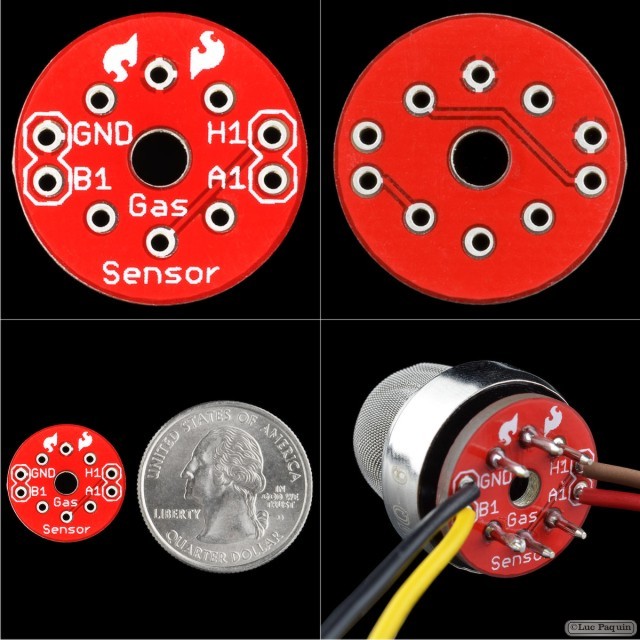
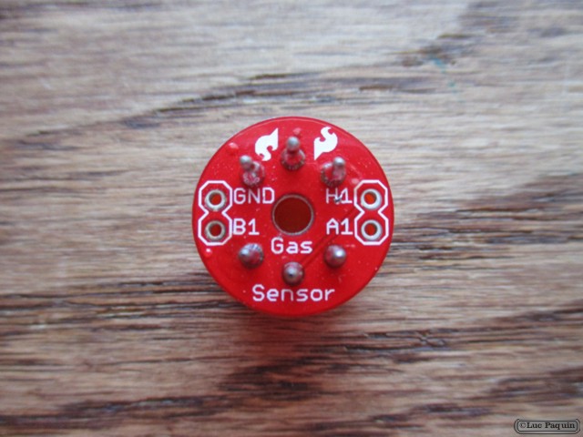
SparkFun: BOB-08891
Description: Simple breakout board for the MQ – 3, MQ – 4 and MQ – 6 gas sensors. All you need is VCC at 5V, GND, and a resistor to an ADC, that is it.
Note: This is the PCB only. Sensors listed below.
Dimensions: 16.8mm diameter
Don Luc
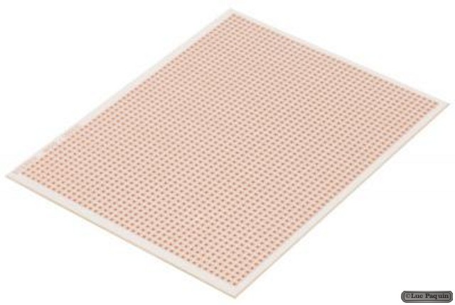
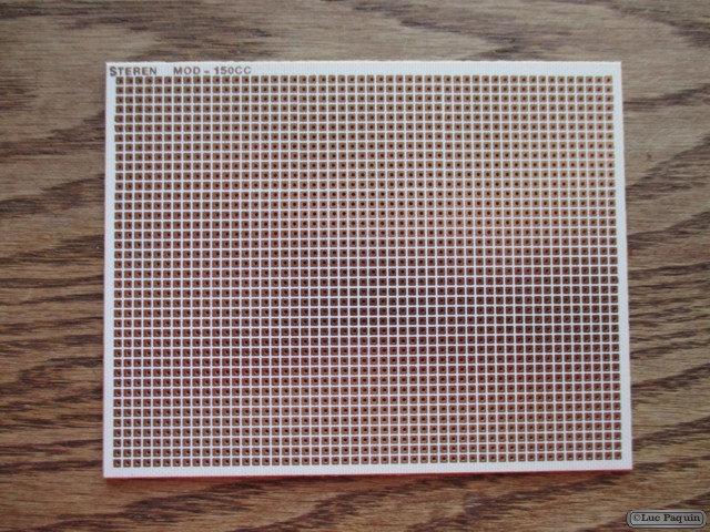
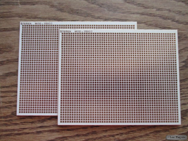
Steren: 150CC
Description: Phenolic copper plate 10.7 x 14 cm (1/4 carte), engraved and perforated. Ideal for projects or prototypes.
Don Luc
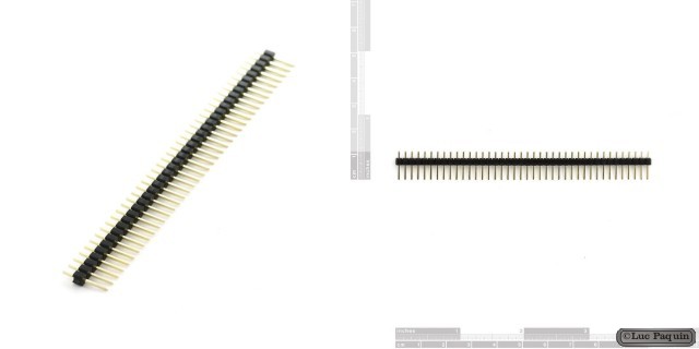
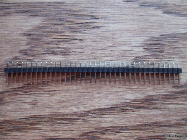
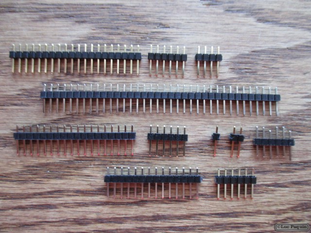
SparkFun: PRT-00116
Description: A row of headers – break to fit. 40 pins that can be cut to any size. Used with custom PCBs or general custom headers.
Features:
Don Luc
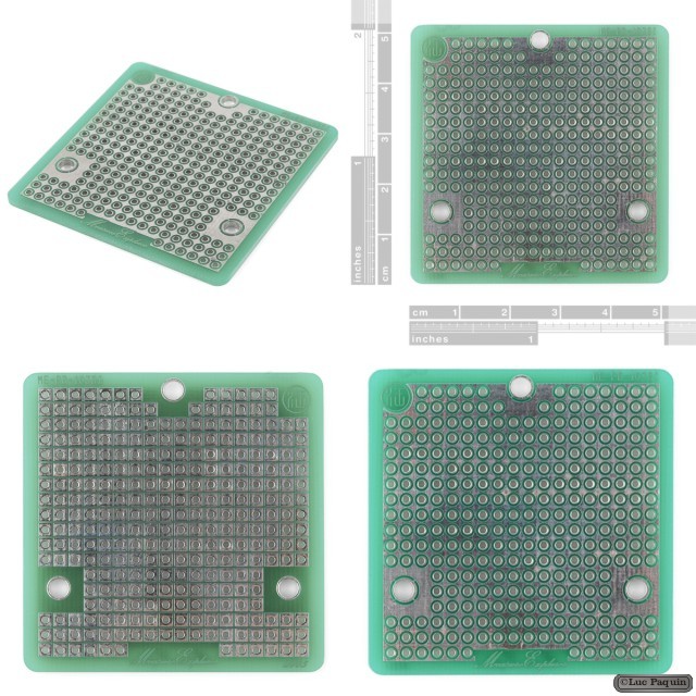
SparkFun: PRT-08811
Description: This is a very simple but handy, 2″ square, double sided perf board. Standard 0.1″ spacing with a 4-40 (3mm) holes for mounting. Great for quickly prototyping stackable circuits.
Don Luc