
LED RGB
LED RGB are tri-color LEDs with red, green, and blue emitters, in general using a four-wire connection with one common lead (anode or cathode). These LEDs can have either common positive leads in the case of a common anode LED, or common negative leads in the case of a common cathode LED. Others, however, have only two leads (positive and negative) and have a built-in electronic control unit.
LED RGB (Red-Green-Blue) are actually three LEDs in one! But that doesn’t mean it can only make three colors. Because red, green, and blue are the additive primary colors, you can control the intensity of each to create every color of the rainbow. Most RGB LEDs have four pins: one for each color, and a common pin. On some, the common pin is the anode, and on others, it’s the cathode.
Circuit Schematics (Common Cathode)
The cathode will be connected to the VIN and will be connected through 330 Ohms resistor. We will use PWM for simulating analog output which will provide different voltage levels to the LEDs so we can get the desired colors. We will use PWM for simulating analog output which will provide different voltage levels to the LEDs so we can get the desired colors.
Source Code
I will use the pins number 4, 3 and 2 and I will name them iRed, iGreen and iBlue. In the setup section we need to define them as outputs. At the bottom of the sketch we have this custom made function named setColor() which takes 3 different arguments red, green and blue. These arguments represents the brightness of the LEDs or the duty cycle of the PWM signal which is created using the analogWrite() function. These values can vary from 0 to 255 which represents 100 % duty cycle of the PWM signal or maximum LED brightness.
So now in the loop function we will make our program which will change the color of the LED each 2 second. In order to get red light on the LED we will call the setColor() function and set value of 255 for the iRed argument and 0 for the two others. Respectively we can get the two other basic colors, green and blue.
DonLuc1807Mk09
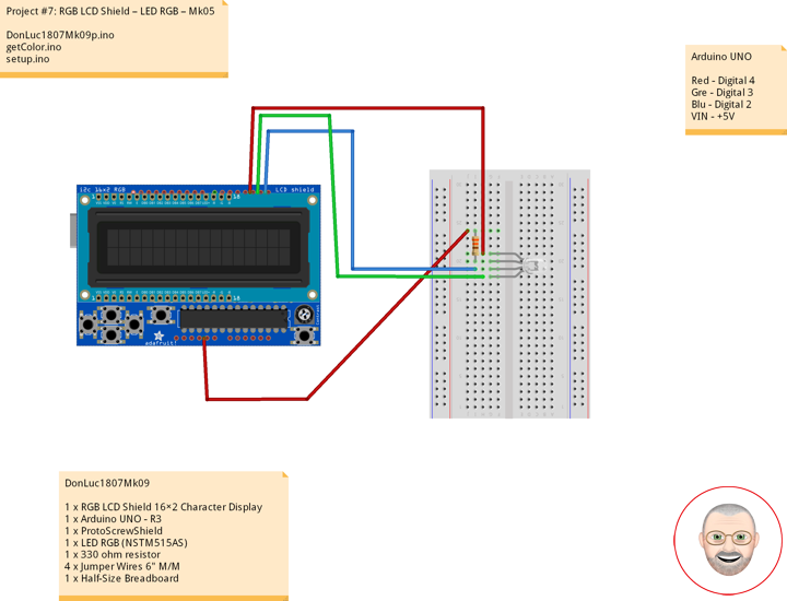
1 x RGB LCD Shield 16×2 Character Display
1 x Arduino UNO – R3
1 x ProtoScrewShield
1 x LED RGB (NSTM515AS)
1 x 330 ohm resistor
4 x Jumper Wires 6″ M/M
1 x Half-Size Breadboard
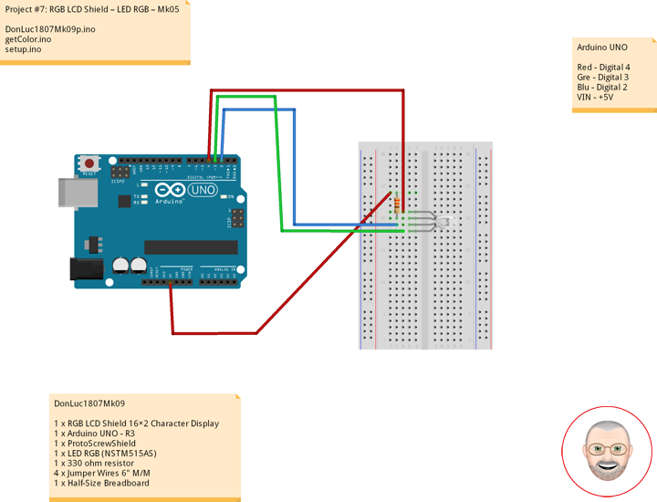
Arduino UNO
Red – Digital 4
Gre – Digital 3
Blu – Digital 2
VIN – +5V
DonLuc1807Mk09p.ino
// ***** Don Luc *****
// Software Version Information
// Project #7: RGB LCD Shield – LED RGB – Mk05
// 7-9
// DonLuc1807Mk09p 7-9
// RGB LCD Shield
// LED RGB

// include the library code:
#include <Adafruit_MCP23017.h>
#include <Adafruit_RGBLCDShield.h>

Adafruit_RGBLCDShield RGBLCDShield = Adafruit_RGBLCDShield();
#define GREEN 0x2

// LED RGB
#define COMMON_ANODE
int iBlue = 2;
int iGreen = 3;
int iRed = 4;

void loop()
{

  // LED RGB
  isColor();

  delay(500);

  // Clear
  RGBLCDShield.clear();

}
getColor.ino
// LED RGB
void isColor()
{
// Display
// Set the cursor to column 0, line 0
RGBLCDShield.setCursor(0,0);
RGBLCDShield.print("LED RGB"); // LED RGB
// Set the cursor to column 0, line 1
RGBLCDShield.setCursor(0, 1);
RGBLCDShield.print("Red "); // Red
setColor(255, 0, 0); // Red Color
delay(2000);
// Set the cursor to column 0, line 1
RGBLCDShield.setCursor(0, 1);
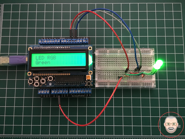
RGBLCDShield.print("Green "); // Green
setColor(0, 255, 0); // Green Color
delay(2000);
// Set the cursor to column 0, line 1
RGBLCDShield.setCursor(0, 1);
RGBLCDShield.print("Blue "); // Blue
setColor(0, 0, 255); // Blue Color
delay(2000);
}
void setColor(int red, int green, int blue)
{
#ifdef COMMON_ANODE
red = 255 - red;
green = 255 - green;
blue = 255 - blue;
#endif
analogWrite(iRed, red);
analogWrite(iGreen, green);
analogWrite(iBlue, blue);
}
setup.ino
// Setup
void setup()
{

  // set up the LCD's number of columns and rows:
  RGBLCDShield.begin(16, 2);
  RGBLCDShield.setBacklight(GREEN);

  // Display
  // Set the cursor to column 0, line 0
  RGBLCDShield.setCursor(0,0);
  RGBLCDShield.print("Don Luc");         // Don luc
  // Set the cursor to column 0, line 1
  RGBLCDShield.setCursor(0, 1);
  RGBLCDShield.print("LED RGB");         // LED RGB

  delay(5000);

  // Clear
  RGBLCDShield.clear();

  // LED RGB
  pinMode(iBlue, OUTPUT);                 // Blue
  pinMode(iGreen, OUTPUT);                // Green
  pinMode(iRed, OUTPUT);                  // Red

}
Don Luc