Seven-Segment Display
A seven-segment display (SSD), or seven-segment indicator, is a form of electronic display device for displaying decimal numerals that is an alternative to the more complex dot matrix displays.
Seven-segment displays are widely used in digital clocks, electronic meters, basic calculators, and other electronic devices that display numerical information.
Your basic 7-segment LED. Common anode. Two decimal points, but only the one on the right is wired. Digit height is 0.6″. Overall height is 1″.
Common Cathode
In a common-cathode display, the positive terminal of all the eight LEDs are connected together and then connected to iSeven2 and iSeven8. To turn on an individual segment, you ground one of the pins. The following diagram shows the internal structure of the common-cathode seven-segment display.
The internal structure of both types is nearly the same. The difference is the polarity of the LEDs and common terminal. In a common cathode seven-segment display, all seven LEDs plus a dot LED have the cathodes connected To use this display, we need to connect VIN to make the individual segments light up. The following diagram shows the internal structure of common-cathode seven-segment display.
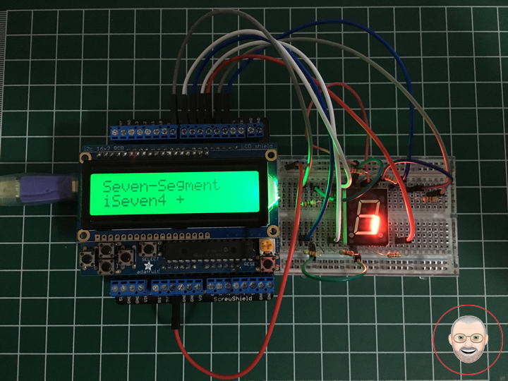
If your Arduino application only needs to display numbers, consider using a seven-segment display. The severn-segment display has seven LEDs arranged in the shape of number eight. They are easy to use and cost effective. The picture below shows a typical seven-segment display.
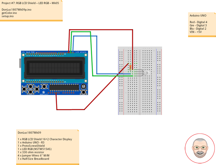
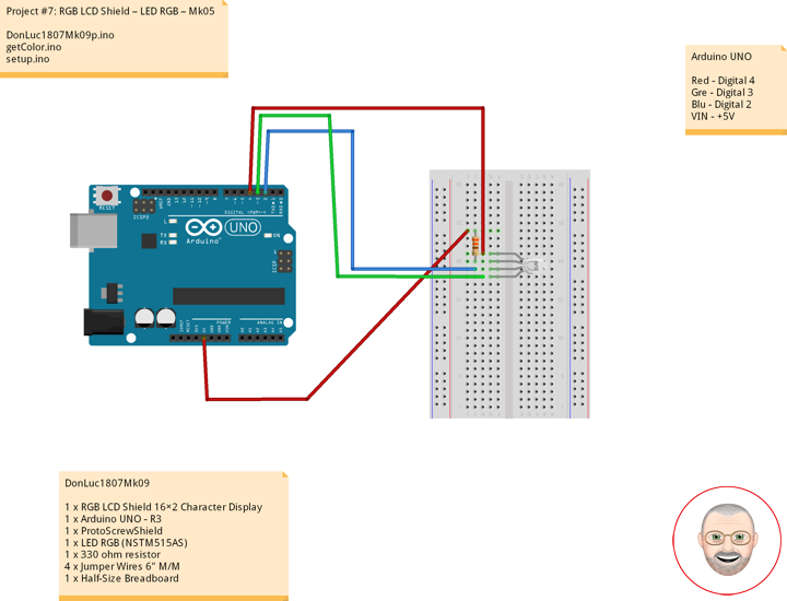
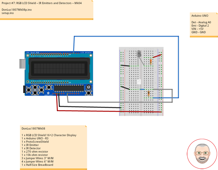
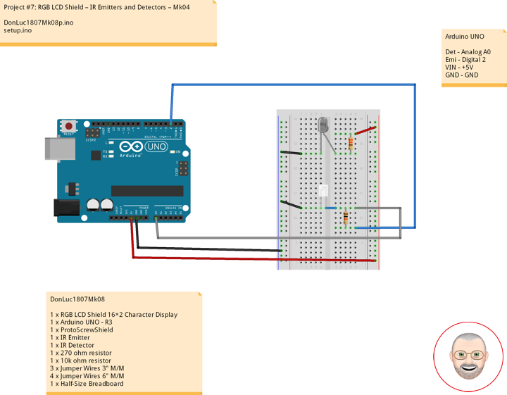
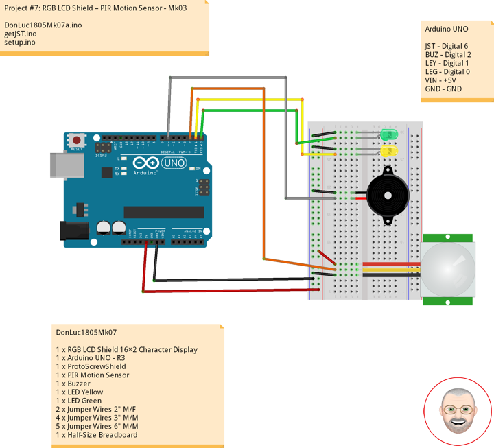
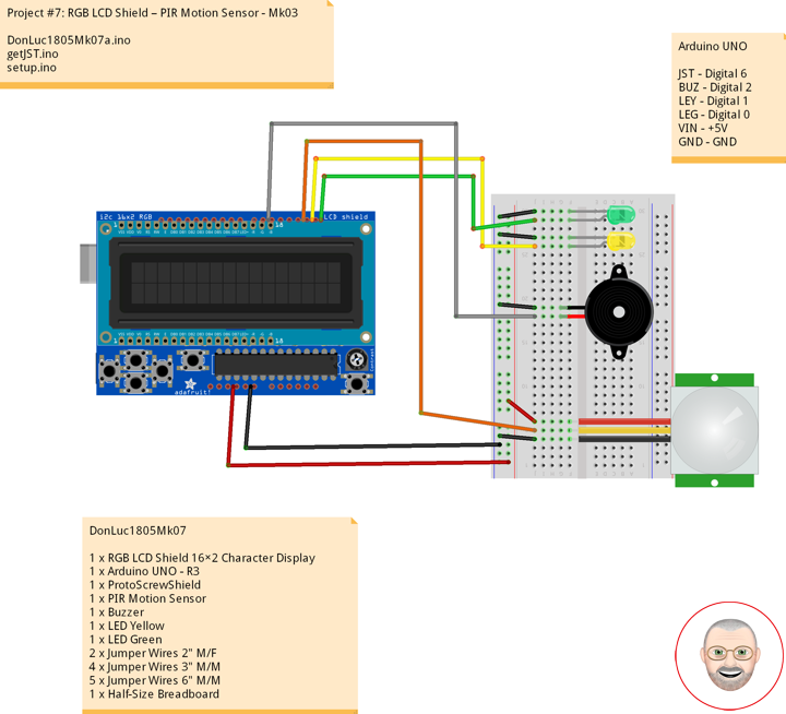
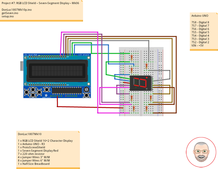
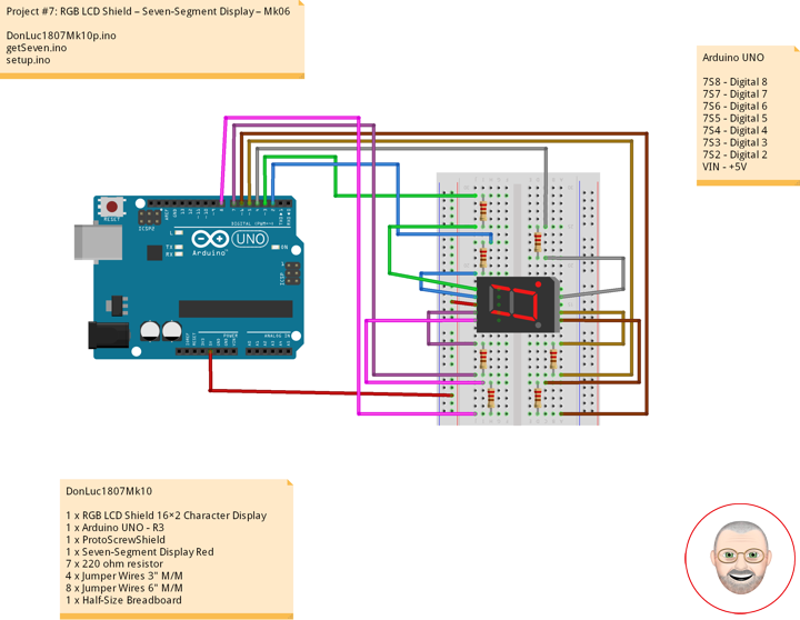
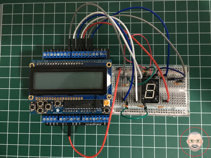
DonLuc1807Mk10
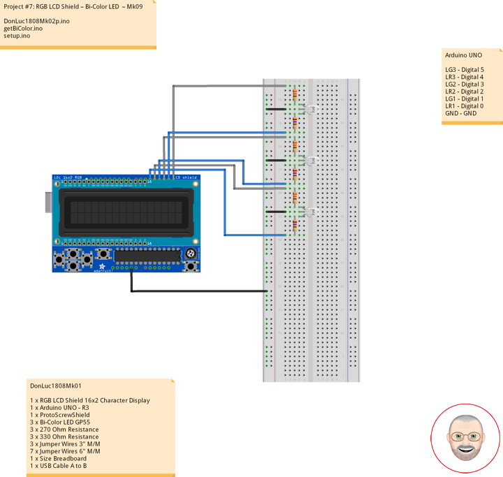
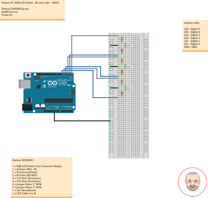
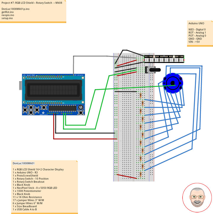
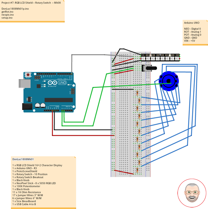
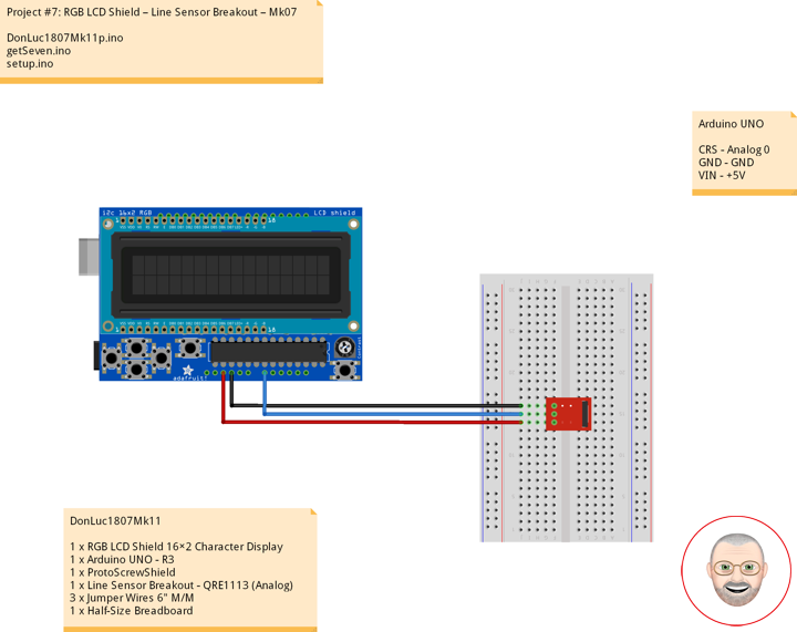
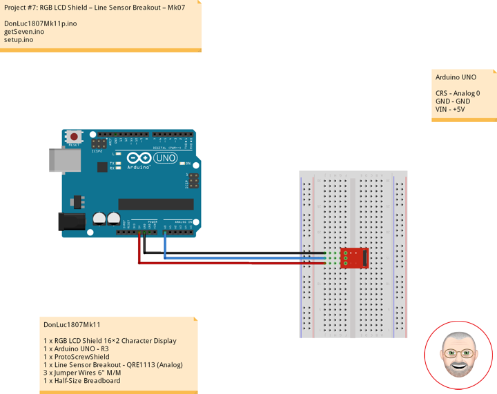
1 x RGB LCD Shield 16×2 Character Display
1 x Arduino UNO – R3
1 x ProtoScrewShield
1 x Seven-Segment Display Red
7 x 220 ohm resistor
4 x Jumper Wires 3″ M/M
8 x Jumper Wires 6″ M/M
1 x Half-Size Breadboard
Arduino UNO
7S8 – Digital 8
7S7 – Digital 7
7S6 – Digital 6
7S5 – Digital 5
7S4 – Digital 4
7S3 – Digital 3
7S2 – Digital 2
VIN – +5V
DonLuc1807Mk10p.ino
// ***** Don Luc *****
// Software Version Information
// Project #7: RGB LCD Shield – Seven-Segment Display – Mk06
// 7-10
// DonLuc1807Mk10p 7-10
// RGB LCD Shield
// Seven-Segment Display

// include the library code:
#include <Adafruit_MCP23017.h>
#include <Adafruit_RGBLCDShield.h>

Adafruit_RGBLCDShield RGBLCDShield = Adafruit_RGBLCDShield();
#define GREEN 0x2

// Seven-Segment Display
int iSeven2 = 2;     // iSeven2
int iSeven3 = 3;     // iSeven3
int iSeven4 = 4;     // iSeven4
int iSeven5 = 5;     // iSeven5
int iSeven6 = 6;     // iSeven6
int iSeven7 = 7;     // iSeven7
int iSeven8 = 8;     // iSeven8

void loop()
{

  // Seven-Segment Display
  isSeven();

  // Clear
  RGBLCDShield.clear();

}
getSeven.ino
// Seven-Segment Display
void isSeven()
{

  // Display
  // Set the cursor to column 0, line 0
  RGBLCDShield.setCursor(0,0);
  RGBLCDShield.print("Seven-Segment");          // Seven-Segment Display

  // Set the cursor to column 0, line 1
  RGBLCDShield.setCursor(0, 1);
  RGBLCDShield.print("iSeven2 +    ");          // iSeven2 +
  digitalWrite(iSeven2, LOW);

  delay(5000);

  // Seven - Off
  isSevOff();

  // Set the cursor to column 0, line 1
  RGBLCDShield.setCursor(0, 1);
  RGBLCDShield.print("iSeven2 -      ");        // iSeven2 -

  delay(2000);

  // Set the cursor to column 0, line 1
  RGBLCDShield.setCursor(0, 1);
  RGBLCDShield.print("iSeven3 +    ");          // iSeven3 +
  digitalWrite(iSeven3, LOW);

  delay(5000);

  // Seven - Off
  isSevOff();

  // Set the cursor to column 0, line 1
  RGBLCDShield.setCursor(0, 1);
  RGBLCDShield.print("iSeven3 -      ");        // iSeven3 -

  delay(2000);

  // Set the cursor to column 0, line 1
  RGBLCDShield.setCursor(0, 1);
  RGBLCDShield.print("iSeven4 +   ");           // iSeven4 +
  digitalWrite(iSeven4, LOW);

  delay(5000);

  // Seven - Off
  isSevOff();

  // Set the cursor to column 0, line 1
  RGBLCDShield.setCursor(0, 1);
  RGBLCDShield.print("iSeven4 -      ");        // iSeven4 -

  delay(2000);

  // Set the cursor to column 0, line 1
  RGBLCDShield.setCursor(0, 1);
  RGBLCDShield.print("iSeven5 +   ");           // iSeven5 +
  digitalWrite(iSeven5, LOW);

  delay(5000);

  // Seven - Off
  isSevOff();

  // Set the cursor to column 0, line 1
  RGBLCDShield.setCursor(0, 1);
  RGBLCDShield.print("iSeven5 -      ");        // iSeven5 -

  delay(2000);

  // Set the cursor to column 0, line 1
  RGBLCDShield.setCursor(0, 1);
  RGBLCDShield.print("iSeven6 +   ");           // iSeven6 +
  digitalWrite(iSeven6, LOW);

  delay(5000);

  // Seven - Off
  isSevOff();

  // Set the cursor to column 0, line 1
  RGBLCDShield.setCursor(0, 1);
  RGBLCDShield.print("iSeven6 -      ");        // iSeven6 -

  delay(2000);

  // Set the cursor to column 0, line 1
  RGBLCDShield.setCursor(0, 1);
  RGBLCDShield.print("iSeven7 +   ");           // iSeven7 +
  digitalWrite(iSeven7, LOW);

  delay(5000);

  // Seven - Off
  isSevOff();

  // Set the cursor to column 0, line 1
  RGBLCDShield.setCursor(0, 1);
  RGBLCDShield.print("iSeven7 -      ");        // iSeven7 -

  delay(2000);

  // Set the cursor to column 0, line 1
  RGBLCDShield.setCursor(0, 1);
  RGBLCDShield.print("iSeven8 +   ");           // iSeven8 +
  digitalWrite(iSeven8, LOW);

  delay(5000);

  // Seven - Off
  isSevOff();

  // Set the cursor to column 0, line 1
  RGBLCDShield.setCursor(0, 1);
  RGBLCDShield.print("iSeven8 -      ");        // iSeven8 -

  delay(2000);

  // Set the cursor to column 0, line 1
  RGBLCDShield.setCursor(0, 1);
  RGBLCDShield.print("iSeven 0    ");           // iSeven 0
  digitalWrite(iSeven2, LOW);
  digitalWrite(iSeven3, LOW);
  digitalWrite(iSeven4, LOW);
  digitalWrite(iSeven5, LOW);
  digitalWrite(iSeven6, LOW);
  digitalWrite(iSeven7, LOW);

  delay(5000);

  // Seven - Off
  isSevOff();

  // Set the cursor to column 0, line 1
  RGBLCDShield.setCursor(0, 1);
  RGBLCDShield.print("Seven - Off    ");        // Seven - Off

  delay(2000);

  // Set the cursor to column 0, line 1
  RGBLCDShield.setCursor(0, 1);
  RGBLCDShield.print("iSeven 1    ");           // iSeven 1
  digitalWrite(iSeven3, LOW);
  digitalWrite(iSeven4, LOW);

  delay(5000);

  // Seven - Off
  isSevOff();

  // Set the cursor to column 0, line 1
  RGBLCDShield.setCursor(0, 1);
  RGBLCDShield.print("Seven - Off    ");        // Seven - Off

  delay(2000);

  // Set the cursor to column 0, line 1
  RGBLCDShield.setCursor(0, 1);
  RGBLCDShield.print("iSeven 2    ");           // iSeven 2
  digitalWrite(iSeven2, LOW);
  digitalWrite(iSeven3, LOW);
  digitalWrite(iSeven5, LOW);
  digitalWrite(iSeven6, LOW);
  digitalWrite(iSeven8, LOW);

  delay(5000);

  // Seven - Off
  isSevOff();

  // Set the cursor to column 0, line 1
  RGBLCDShield.setCursor(0, 1);
  RGBLCDShield.print("Seven - Off    ");        // Seven - Off

  delay(2000);

  // Set the cursor to column 0, line 1
  RGBLCDShield.setCursor(0, 1);
  RGBLCDShield.print("iSeven 3    ");           // iSeven 3
  digitalWrite(iSeven2, LOW);
  digitalWrite(iSeven3, LOW);
  digitalWrite(iSeven4, LOW);
  digitalWrite(iSeven5, LOW);
  digitalWrite(iSeven8, LOW);

  delay(5000);

  // Seven - Off
  isSevOff();

  // Set the cursor to column 0, line 1
  RGBLCDShield.setCursor(0, 1);
  RGBLCDShield.print("Seven - Off    ");        // Seven - Off

  delay(2000);

  // Set the cursor to column 0, line 1
  RGBLCDShield.setCursor(0, 1);
  RGBLCDShield.print("iSeven 4    ");           // iSeven 4
  digitalWrite(iSeven3, LOW);
  digitalWrite(iSeven4, LOW);
  digitalWrite(iSeven7, LOW);
  digitalWrite(iSeven8, LOW);

  delay(5000);

  // Seven - Off
  isSevOff();

  // Set the cursor to column 0, line 1
  RGBLCDShield.setCursor(0, 1);
  RGBLCDShield.print("Seven - Off    ");        // Seven - Off

  delay(2000);

  // Set the cursor to column 0, line 1
  RGBLCDShield.setCursor(0, 1);
  RGBLCDShield.print("iSeven 5    ");           // iSeven 5
  digitalWrite(iSeven2, LOW);
  digitalWrite(iSeven4, LOW);
  digitalWrite(iSeven5, LOW);
  digitalWrite(iSeven7, LOW);
  digitalWrite(iSeven8, LOW);

  delay(5000);

  // Seven - Off
  isSevOff();

  // Set the cursor to column 0, line 1
  RGBLCDShield.setCursor(0, 1);
  RGBLCDShield.print("Seven - Off    ");        // Seven - Off

  delay(2000);

  // Set the cursor to column 0, line 1
  RGBLCDShield.setCursor(0, 1);
  RGBLCDShield.print("iSeven 6    ");           // iSeven 6
  digitalWrite(iSeven2, LOW);
  digitalWrite(iSeven4, LOW);
  digitalWrite(iSeven5, LOW);
  digitalWrite(iSeven6, LOW);
  digitalWrite(iSeven7, LOW);
  digitalWrite(iSeven8, LOW);

  delay(5000);

  // Seven - Off
  isSevOff();

  // Set the cursor to column 0, line 1
  RGBLCDShield.setCursor(0, 1);
  RGBLCDShield.print("Seven - Off    ");        // Seven - Off

  delay(2000);

  // Set the cursor to column 0, line 1
  RGBLCDShield.setCursor(0, 1);
  RGBLCDShield.print("iSeven 7    ");           // iSeven 7
  digitalWrite(iSeven2, LOW);
  digitalWrite(iSeven3, LOW);
  digitalWrite(iSeven4, LOW);

  delay(5000);

  // Seven - Off
  isSevOff();

  // Set the cursor to column 0, line 1
  RGBLCDShield.setCursor(0, 1);
  RGBLCDShield.print("Seven - Off    ");        // Seven - Off

  delay(2000);

  // Set the cursor to column 0, line 1
  RGBLCDShield.setCursor(0, 1);
  RGBLCDShield.print("iSeven 8    ");           // iSeven 8
  digitalWrite(iSeven2, LOW);
  digitalWrite(iSeven3, LOW);
  digitalWrite(iSeven4, LOW);
  digitalWrite(iSeven5, LOW);
  digitalWrite(iSeven6, LOW);
  digitalWrite(iSeven7, LOW);
  digitalWrite(iSeven8, LOW);

  delay(5000);

  // Seven - Off
  isSevOff();

  // Set the cursor to column 0, line 1
  RGBLCDShield.setCursor(0, 1);
  RGBLCDShield.print("Seven - Off    ");        // Seven - Off

  delay(2000);

  // Set the cursor to column 0, line 1
  RGBLCDShield.setCursor(0, 1);
  RGBLCDShield.print("iSeven 9    ");           // iSeven 9
  digitalWrite(iSeven2, LOW);
  digitalWrite(iSeven3, LOW);
  digitalWrite(iSeven4, LOW);
  digitalWrite(iSeven5, LOW);
  digitalWrite(iSeven7, LOW);
  digitalWrite(iSeven8, LOW);

  delay(5000);

  // Seven - Off
  isSevOff();

  // Set the cursor to column 0, line 1
  RGBLCDShield.setCursor(0, 1);
  RGBLCDShield.print("Seven - Off    ");        // Seven - Off

  delay(2000);

}

// Seven - Off
void isSevOff()
{

  // Seven - Off
  digitalWrite(iSeven2, HIGH);
  digitalWrite(iSeven3, HIGH);
  digitalWrite(iSeven4, HIGH);
  digitalWrite(iSeven5, HIGH);
  digitalWrite(iSeven6, HIGH);
  digitalWrite(iSeven7, HIGH);
  digitalWrite(iSeven8, HIGH);

}
setup.ino
// Setup
void setup()
{

  // set up the LCD's number of columns and rows:
  RGBLCDShield.begin(16, 2);
  RGBLCDShield.setBacklight(GREEN);

  // Display
  // Set the cursor to column 0, line 0
  RGBLCDShield.setCursor(0,0);
  RGBLCDShield.print("Don Luc");           // Don luc
  // Set the cursor to column 0, line 1
  RGBLCDShield.setCursor(0, 1);
  RGBLCDShield.print("Seven-Segment");     // Seven-Segment Display
  delay(5000);

  // Clear
  RGBLCDShield.clear();

  // Seven-Segment Display
  pinMode(iSeven2, OUTPUT);                // iSeven2
  pinMode(iSeven3, OUTPUT);                // iSeven3
  pinMode(iSeven4, OUTPUT);                // iSeven4
  pinMode(iSeven5, OUTPUT);                // iSeven5
  pinMode(iSeven6, OUTPUT);                // iSeven6
  pinMode(iSeven7, OUTPUT);                // iSeven7
  pinMode(iSeven8, OUTPUT);                // iSeven8

  isSevOff();                              // Seven - Off

}
Don Luc