Adafruit: 1304
Description
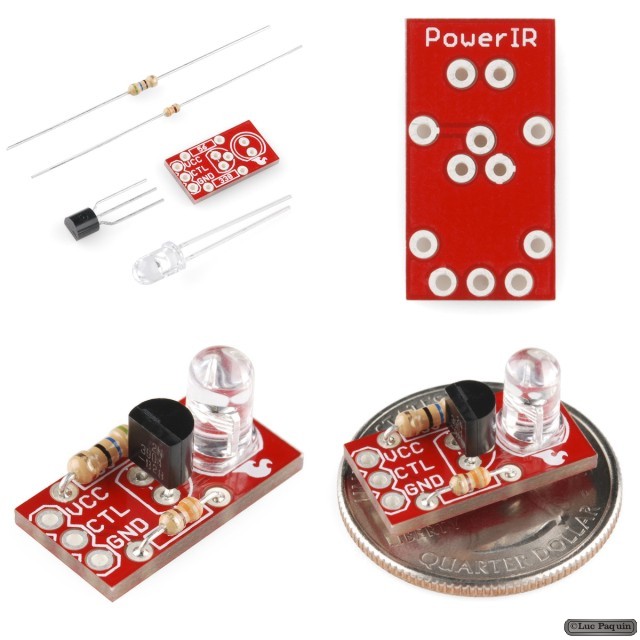
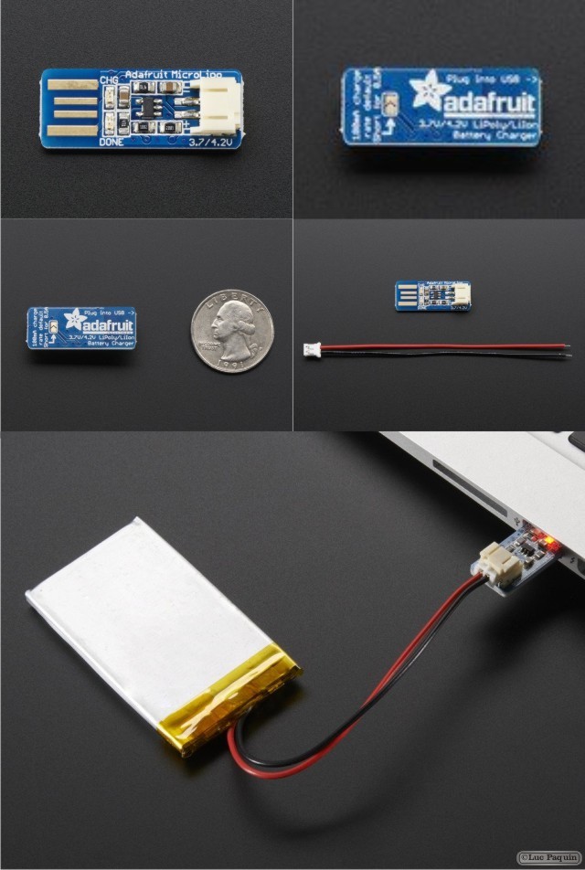
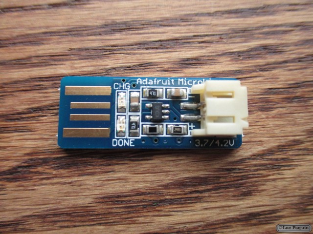
Oh so adorable, this is the tiniest little lipo charger, so handy you can keep it any project box! Its also easy to use. Simply plug in the gold plated contacts into any USB port and a 3.7V/4.2V lithium polymer or lithium ion rechargeable battery into the JST plug on the other end. There are two LEDs – one red and one green. While charging, the red LED is lit. When the battery is fully charged and ready for use, the green LED turns on. Seriously, it could not get more easy.
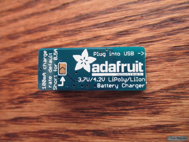
Charging is performed in three stages: first a preconditioning charge, then a constant-current fast charge and finally a constant-voltage trickle charge to keep the battery topped-up. The charge current is 100mA by default, so it will work with any size battery and USB port. If you want you can easily change it over to 500mA mode by soldering closed the jumper on the back, for when you’ll only be charging batteries with 500mAh size or larger.
For use with Adafruit LiPoly/LiIon batteries only! Other batteries may have different voltage, chemistry, polarity or pinout.
- Comes assembled and tested with a free bonus JST cable!
- 5V input via PCB-style USB connector
- For charging single Lithium Ion/Lithium Polymer 3.7/4.2v batteries (not for older 3.6/4.1v cells)
- 100mA charge current, adjustable to 500mA by soldering a jumper closed
- Free 2-pin JST cable included!
Don Luc