Adafruit: 659
Description
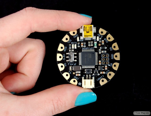
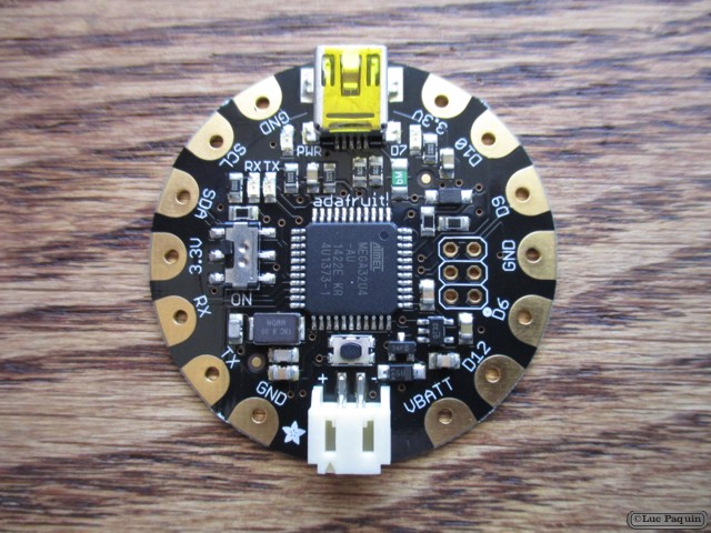
FLORA is Adafruit’s fully-featured wearable electronics platform. It’s a round, sewable, Arduino-compatible microcontroller designed to empower amazing wearables projects.
The FLORA is small (1.75″ diameter, weighing 4.4 grams). The FLORA family also has the best stainless steel threads, sensors, GPS modules and chainable LED NeoPixels, perfect accessories for the FLORA main board.
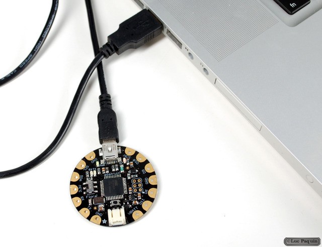
The FLORA has built-in USB support. Built in USB means you plug it in to program it, it just shows up – all you need is a Micro-B USB cable, no additional purchases are needed! We have a modified version of the Arduino IDE so Mac & Windows users can get started fast – or with the new 1.6.4+ Arduino IDE, it takes only a few seconds to add Flora-support. The FLORA has USB HID support, so it can act like a mouse or keyboard to attach directly to computers.
The FLORA has built-in USB support. Built in USB means you plug it in to program it, it just shows up – all you need is a Micro-B USB cable, no additional purchases are needed! We have a modified version of the Arduino IDE so Mac & Windows users can get started fast – or with the new 1.6.4+ Arduino IDE, it takes only a few seconds to add Flora-support. The FLORA has USB HID support, so it can act like a mouse or keyboard to attach directly to computers.
FLORA has onboard power switch connected to 2A power FET for safe and efficient battery on/off control, so you can power quite a bit without burning out your switch. The FLORA has an onboard 3.3v 250mA regulator with a protection diode and USB fuse so that the microcontroller voltage is consistent and can power common 3.3v modules and sensors.
We spent a lot of time on the power supply because the FLORA power system is specifically designed to allow easy control and power of a large quantity of addressable NeoPixels. Flora can easily drive 50 pixels directly from the onboard power supply, or up to 500 with the pixels externally powered by a separate 5V supply.
- FLORA is fabric friendly– all the components on board are flush to the PCB and won’t snag delicate garments (it does not use FTDI headers).
- FLORA is extremely beginner-friendly – it is difficult to destroy the FLORA by connecting a battery backwards due to polarized connector and protection diodes. The on-board regulator means that even connecting a 9V battery will not result in damage or tears.
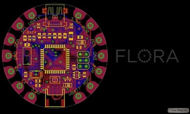
- The FLORA has 4 indicator LEDs: power good, digital signal LED for bootloader feedback, data rx/tx. Also onboard is an ICSP connector for easy reprograming for advanced users. Flora v2 even has an RGB NeoPixel for even more colorful lighting.
- There are 14 sewing tap pads for attachment and electrical connections. Data buses are interleaved with power and ground pads for easy module and sensor attachments without worrying about overlapping traces which are not possible with conductive thread.
- The FLORA works great with the Arduino IDE and is super easy to install support if you have IDE 1.6.4 or later
The FLORA is not the first wearable Arduino / Arduino-compatible. Leah Buechley’s Lilypad was developed in 2007 and while they are both round, FLORA is a completely new platform that works seamlessly with the FLORA accessories.
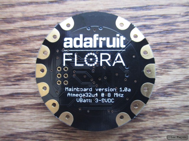
The FLORA is made in NYC at Adafruit, it was designed by Limor Fried (Ladyada), Adafruit’s founder and engineer. Adafruit has a proven track record of providing 100+ high-quality libraries for Arduino/Arduino IDE, hundreds of tutorials, open-source code and contributions to the Arduino project. Ladyada was a member of the MIT wearables group and likes to sew.
You may get an off-white or black JST connector.
Technical Details
- Dimensions: 45mm round x 7mm thick/ 1.8″ round x 0.3″ thick
- Weight: 4.7g
Don Luc