
Don Luc
In my early teens I was into photography and processing and printing my own B&W photos in a darkroom I had built with the help of my Mom in our basement in Canada. I got into electronics when I could not afford to buy a proper darkroom timer and I saw some article, probably in some electronics magazine, that explained how to build a simple timer that blinks a LED at one second intervals. After a trip, probably to Radio Shack, to buy a 555 timer IC, a LED, some resistors, wires and a small perforated circuit board. After that I was hooked on electronics projects from that day.
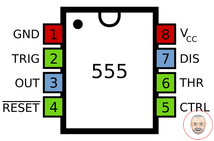
555 Timer IC
The 555 timer IC is an integrated circuit (chip) used in a variety of timer, pulse generation, and oscillator applications. The 555 can be used to provide time delays, as an oscillator, and as a flip-flop element.
Introduced in 1972 by Signetics, the 555 is still in widespread use due to its low price, ease of use, and stability. It is now made by many companies in the original bipolar and in low-power CMOS technologies. As of 2003, it was estimated that 1 billion units were manufactured every year. The 555 is the most popular integrated circuit ever manufactured. This is a small size led flasher built with the 555 timer IC that is powered from DC Power Supply. The circuit can be used as a flashing metronome, dark room timer, memo-reminder or other similar applications.
Specifications
These specifications apply to the NE555. Other 555 timers can have different specifications depending on the grade (military, medical, etc.). These values should be considered “ball park” values, instead the current official datasheet from the exact manufacturer of each chip should be consulted for parameter limitation recommendations.
Supply voltage (VCC): 4.5 to 15 V
Supply current (VCC = +5 V): 3 to 6 mA
Supply current (VCC = +15 V): 10 to 15 mA
Output current (maximum): 200 mA
Maximum Power dissipation: 600 mW
Power consumption (minimum operating): 30 mW@5V, 225 mW@15V
Operating temperature: 0 to 75 °C
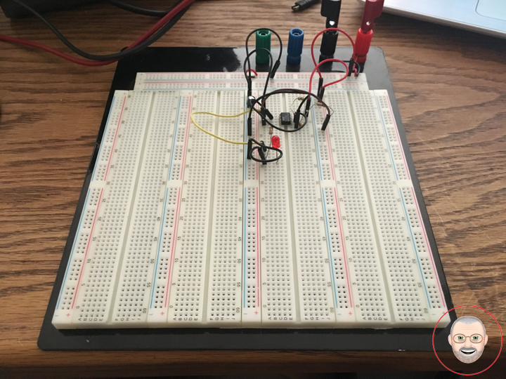
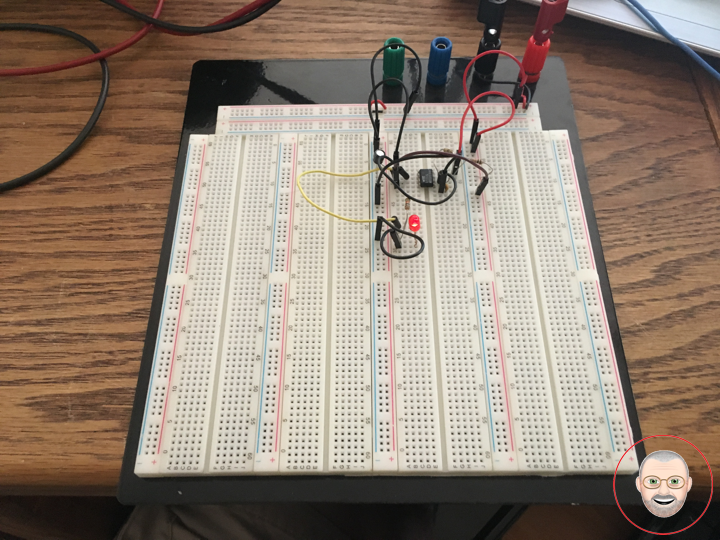
555 Flasher Circuit
Modes: Astable (free-running) mode – the 555 can operate as an electronic oscillator. Uses include LED and lamp flashers, pulse generation, logic clocks, tone generation, security alarms, pulse position modulation and so on. The 555 can be used as a simple ADC, converting an analog value to a pulse length. The use of a microprocessor-based circuit can then convert the pulse period to temperature, linearize it and even provide calibration means.
The LED will be ON for a short period of time and OFF for a longer period. The duty cycle can be reversed if the LED is connected as shown will also increase due to the fact that the LED will stay ON for a longer period of time. An LED flasher circuit is a circuit which flashes the LED meaning turns it ON-OFF, ON-OFF, ON-OFF, Etc.
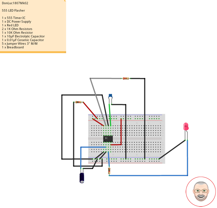
555 LED Flasher
1 x 555 Timer IC
1 x DC Power Supply
1 x Red LED
2 x 1K Ohm Resistors
1 x 10K Ohm Resistor
1 x 10µF Electrolytic Capacitor
1 x 0.01µF Ceramic Capacitor
9 x Jumper Wires 3″ M/M
1 x Breadboard
Don Luc