Electromagnetic Field
An electromagnetic field (also EMF or EM field) is a physical field produced by electrically charged objects. It affects the behavior of charged objects in the vicinity of the field. The electromagnetic field extends indefinitely throughout space and describes the electromagnetic interaction. It is one of the four fundamental forces of nature (the others are gravitation, weak interaction and strong interaction).
The field can be viewed as the combination of an electric field and a magnetic field. The electric field is produced by stationary charges, and the magnetic field by moving charges (currents); these two are often described as the sources of the field. The way in which charges and currents interact with the electromagnetic field is described by Maxwell’s equations and the Lorentz force law. The force created by the electric field is much stronger than the force created by the magnetic field.
From a classical perspective in the history of electromagnetism, the electromagnetic field can be regarded as a smooth, continuous field, propagated in a wavelike manner; whereas from the perspective of quantum field theory, the field is seen as quantized, being composed of individual particles.
EMF Measurement
EMF measurements are measurements of ambient (surrounding) electromagnetic fields that are performed using particular sensors or probes, such as EMF meters. These probes can be generally considered as antennas although with different characteristics. In fact probes should not perturb the electromagnetic field and must prevent coupling and reflection as much as possible in order to obtain precise results. There are two main types of EMF measurements:
* Broadband measurements performed using a broadband probe, that is a device which senses any signal across a wide range of frequencies and is usually made with three independent diode detectors;
* Frequency selective measurements in which the measurement system consists of a field antenna and a frequency selective receiver or spectrum analyzer allowing to monitor the frequency range of interest.
EMF probes may respond to fields only on one axis, or may be tri-axial, showing components of the field in three directions at once. Amplified, active, probes can improve measurement precision and sensitivity but their active components may limit their speed of response.
EMF Meters
An EMF meter is a scientific instrument for measuring electromagnetic fields (abbreviated as EMF). Most meters measure the electromagnetic radiation flux density (DC fields) or the change in an electromagnetic field over time (AC fields), essentially the same as a radio antenna, but with quite different detection characteristics.
The two largest categories are single axis and tri-axis. Single axis meters are cheaper than tri-axis meters, but take longer to complete a survey because the meter only measures one dimension of the field. Single axis instruments have to be tilted and turned on all three axes to obtain a full measurement. A tri-axis meter measures all three axes simultaneously, but these models tend to be more expensive.
Electromagnetic fields can be generated by AC or DC currents. An EMF meter can measure AC electromagnetic fields, which are usually emitted from man-made sources such as electrical wiring, while gaussmeters or magnetometers measure DC fields, which occur naturally in Earth’s geomagnetic field and are emitted from other sources where direct current is present.
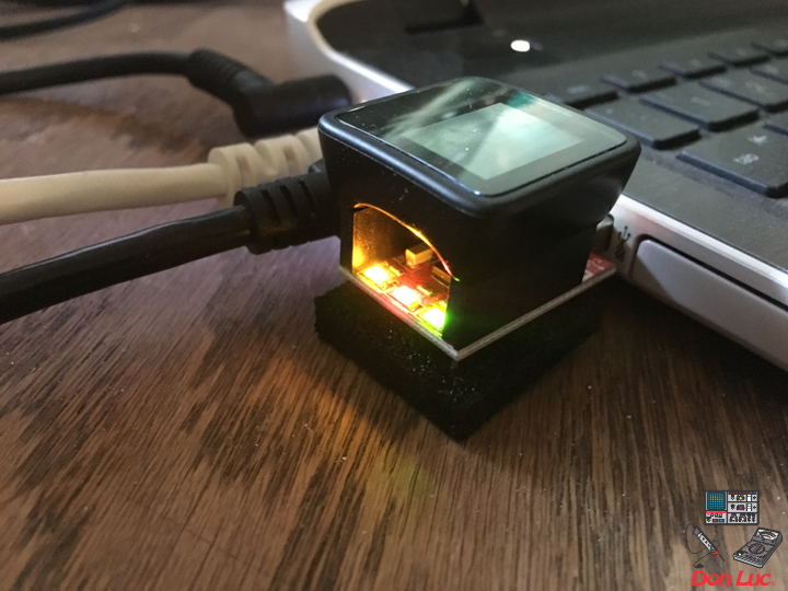
EMF Meter (Single Axis)
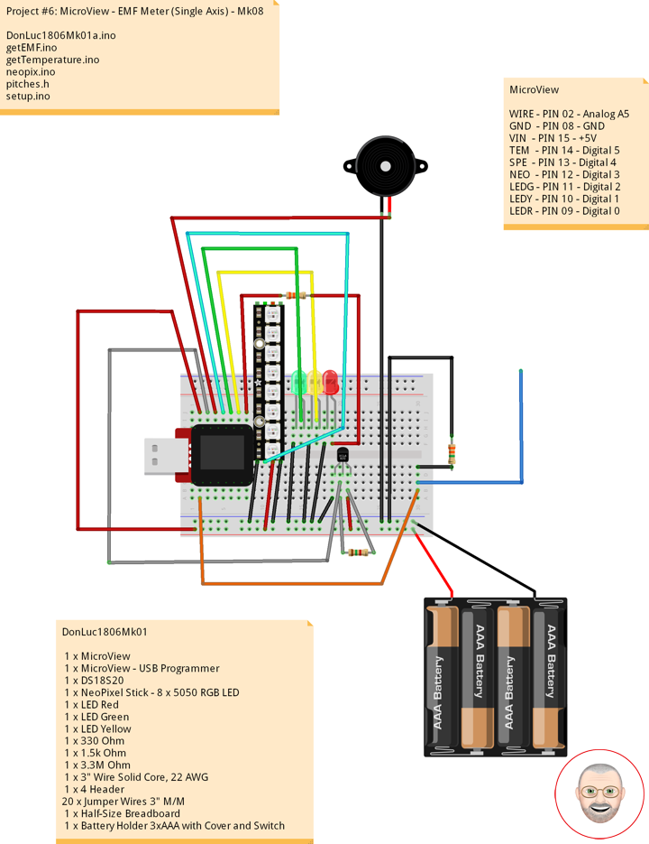
1 x MicroView
1 x MicroView – USB Programmer
1 x DS18S20
1 x NeoPixel Stick – 8 x 5050 RGB LED
1 x Speaker
1 x LED Red
1 x LED Green
1 x LED Yellow
1 x 330 Ohm
1 x 1.5k Ohm
1 x 3.3M Ohm
1 x 3″ Wire Solid Core, 22 AWG
1 x 4 Header
20 x Jumper Wires 3″ M/M
1 x Half-Size Breadboard
1 x Battery Holder 3xAAA with Cover and Switch
3 x Battery AAA
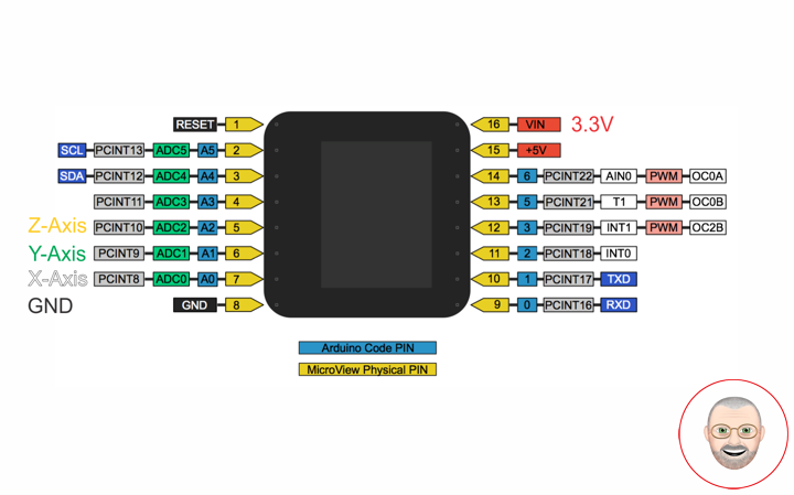
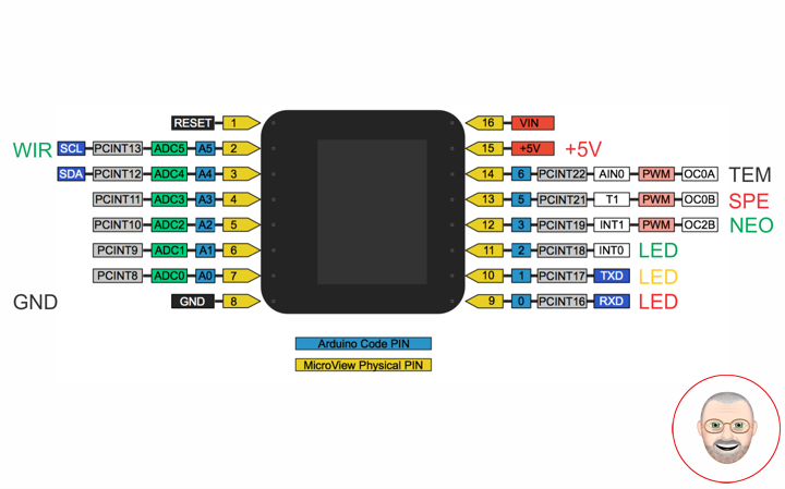
MicroView
WIRE – PIN 02 – Analog A5
GND – PIN 08 – GND
VIN – PIN 15 – +5V
TEM – PIN 14 – Digital 5
SPE – PIN 13 – Digital 4
NEO – PIN 12 – Digital 3
LEDG – PIN 11 – Digital 2
LEDY – PIN 10 – Digital 1
LEDR – PIN 09 – Digital 0
DonLuc1806Mk01
DonLuc1806Mk01a.ino
// ***** Don Luc *****
// Software Version Information
// Project #6: MicroView - EMF Meter (Single Axis) - Mk08
// 6.1
// DonLuc1806Mk01 6-1
// MicroView
// EMF Meter (Single Axis)

// include the library code:
#include <MicroView.h>
#include <Adafruit_NeoPixel.h>
// Pitches
#include "pitches.h"
#include <OneWire.h>

// EMF Meter (Single Axis)
#define NUMREADINGS 15                    // Raise this number to increase data smoothing
int senseLimit = 15;                      // Raise this number to decrease sensitivity (up to 1023 max)
int val = 0;                              // Val
int iEMF = A5;                            // EMF Meter
int readings[ NUMREADINGS ];              // Readings from the analog input
int index = 0;                            // Index of the current reading
int total = 0;                            // Running total
int average = 0;                          // Final average of the probe reading
// NeoPixels
#define PIN 3                             // On digital pin 3
#define NUMPIXELS 8                       // NeoPixels NUMPIXELS = 8
Adafruit_NeoPixel pixels = Adafruit_NeoPixel(NUMPIXELS, PIN, NEO_GRB + NEO_KHZ800);
int red = 0;                              // Red
int green = 0;                            // Green
int blue = 0;                             // Blue
int iNeo = 0;                             // Neopix
int iBri = 0;                             // Neopix Brightness
// LED
int ledR = 0;                             // LED Red
int ledG = 1;                             // LED Green
int ledY = 2;                             // LED Yellow
// 8-ohm speaker
#define tonePIN 5                         // On digital pin 5
// Temperature chip i/o
int DS18S20_Pin = 6;                      // DS18S20 Signal pin on digital 6
OneWire ds(DS18S20_Pin);                  // On digital pin 6
float temperature = 0;                    // Temperature

void loop() {

  // EMF Meter (Single Axis)
  isEMF();

  delay(250);

  uView.clear(PAGE);  // Erase the memory buffer, the OLED will be cleared

}
getEMF.ino
// EMF Meter (Single Axis)
void isEMF(){

  // LEDs - Low
  for(int z=0; z<NUMPIXELS; z++){
     // Black
     red = 0;                                 // Red
     green = 0;                               // Green
     blue = 0;                                // Blue
     iNeo = z;                                // Neopix
     iBri = 0;                                // Neopix Brightness
     neopix();
  }
  digitalWrite(ledG, LOW);                    // Turn that LED off
  digitalWrite(ledY, LOW);                    // Turn that LED off
  noTone(tonePIN);                            // noTone

  // Probe
  val = analogRead( iEMF );                    // Take a reading from the probe

  if( val >= 1 ){                              // If the reading isn't zero, proceed

    val = constrain( val, 1, senseLimit );     // Turn any reading higher than the senseLimit value into the senseLimit value
    val = map( val, 1, senseLimit, 1, 1023 );  // Remap the constrained value within a 1 to 1023 range

    total -= readings[ index ];                // Subtract the last reading
    readings[ index ] = val;                   // Read from the sensor
    total += readings[ index ];                // Add the reading to the total
    index = ( index + 1 );                     // Advance to the next index

    if ( index >= NUMREADINGS ) {              // If we're at the end of the array...
      index = 0;                               // ...wrap around to the beginning
    }

    average = total / NUMREADINGS;             // Calculate the average

    if (average < 50) {                        // If the average is less 50 ...
      digitalWrite(ledG, HIGH);                // turn that LED On
      tone(tonePIN, NOTE_C3);                  // Tone
    }
    else{                                      // and if it's not ...
      digitalWrite(ledG, LOW);                 // turn that LED off
      noTone(tonePIN);                         // noTone
    }

    if (average > 50){                         // If the average is over 50 ...
      // Green
      red = 0;                                 // Red
      green = 255;                             // Green
      blue = 0;                                // Blue
      iNeo = 0;                                // Neopix
      iBri = 100;                              // Neopix Brightness
      neopix();
      tone(tonePIN, NOTE_C4);                  // Tone
    }
    else{                                      // and if it's not ...
      // Black
      red = 0;                                 // Red
      green = 0;                               // Green
      blue = 0;                                // Blue
      iNeo = 0;                                // Neopix
      iBri = 0;                                // Neopix Brightness
      neopix();
      noTone(tonePIN);                         // noTone
    }

    if (average > 250){                        // and so on ...
      // Green
      red = 0;                                 // Red
      green = 255;                             // Green
      blue = 0;                                // Blue
      iNeo = 1;                                // Neopix
      iBri = 100;                              // Neopix Brightness
      neopix();
      tone(tonePIN, NOTE_D4);                  // Tone
    }
    else{
      // Black
      red = 0;                                 // Red
      green = 0;                               // Green
      blue = 0;                                // Blue
      iNeo = 1;                                // Neopix
      iBri = 0;                                // Neopix Brightness
      neopix();
      noTone(tonePIN);                         // noTone
    }

    if (average > 350){
      // Green
      red = 0;                                 // Red
      green = 255;                             // Green
      blue = 0;                                // Blue
      iNeo = 2;                                // Neopix
      iBri = 100;                              // Neopix Brightness
      neopix();
      tone(tonePIN, NOTE_E4);                  // Tone
    }
    else{
      // Black
      red = 0;                                 // Red
      green = 0;                               // Green
      blue = 0;                                // Blue
      iNeo = 1;                                // Neopix
      iBri = 0;                                // Neopix Brightness
      neopix();
      noTone(tonePIN);                         // noTone
    }


    if (average > 500){
      // Yellow
      red = 255;                               // Red
      green = 255;                             // Green
      blue = 0;                                // Blue
      iNeo = 3;                                // Neopix
      iBri = 100;                              // Neopix Brightness
      neopix();
      tone(tonePIN, NOTE_F4);                  // Tone
    }
    else{
      // Black
      red = 0;                                 // Red
      green = 0;                               // Green
      blue = 0;                                // Blue
      iNeo = 3;                                // Neopix
      iBri = 0;                                // Neopix Brightness
      neopix();
      noTone(tonePIN);                         // noTone
    }

    if (average > 650){
      // Yellow
      red = 255;                               // Red
      green = 255;                             // Green
      blue = 0;                                // Blue
      iNeo = 4;                                // Neopix
      iBri = 100;                              // Neopix Brightness
      neopix();
      tone(tonePIN, NOTE_G4);                  // Tone
    }
    else{
      // Black
      red = 0;                                 // Red
      green = 0;                               // Green
      blue = 0;                                // Blue
      iNeo = 4;                                // Neopix
      iBri = 0;                                // Neopix Brightness
      neopix();
      noTone(tonePIN);                         // noTone
    }

    if (average > 750){
      // Yellow
      red = 255;                               // Red
      green = 255;                             // Green
      blue = 0;                                // Blue
      iNeo = 5;                                // Neopix
      iBri = 100;                              // Neopix Brightness
      neopix();
      tone(tonePIN, NOTE_A4);                  // Tone
    }
    else{
      // Black
      red = 0;                                 // Red
      green = 0;                               // Green
      blue = 0;                                // Blue
      iNeo = 5;                                // Neopix
      iBri = 0;                                // Neopix Brightness
      neopix();
      noTone(tonePIN);                         // noTone
    }

    if (average > 850){
      // Red
      red = 255;                               // Red
      green = 0;                               // Green
      blue = 0;                                // Blue
      iNeo = 6;                                // Neopix
      iBri = 100;                              // Neopix Brightness
      neopix();
      tone(tonePIN, NOTE_B4);                  // Tone
    }
    else{
      // Black
      red = 0;                                 // Red
      green = 0;                               // Green
      blue = 0;                                // Blue
      iNeo = 6;                                // Neopix
      iBri = 0;                                // Neopix Brightness
      neopix();
      noTone(tonePIN);                         // noTone
    }

    if (average > 950){
      // Red
      red = 255;                               // Red
      green = 0;                               // Green
      blue = 0;                                // Blue
      iNeo = 7;                                // Neopix
      iBri = 100;                              // Neopix Brightness
      neopix();
      tone(tonePIN, NOTE_C5);                  // Tone
    }
    else{
      // Black
      red = 0;                                 // Red
      green = 0;                               // Green
      blue = 0;                                // Blue
      iNeo = 7;                                // Neopix
      iBri = 0;                                // Neopix Brightness
      neopix();
      noTone(tonePIN);                         // noTone
    }

  }
  else
  {

    digitalWrite(ledY, HIGH);                  // turn that LED On
    noTone(tonePIN);                           // noTone

  }

  uView.setFontType(0);  // Set font type 0: Numbers and letters. 10 characters per line (6 lines)

  uView.setCursor(0,10); // EMF Meter
  uView.print( "EMF: " );
  uView.print( average );

  // Temperature chip i/o
  isTe();

  uView.display();       // Display

}
getTemperature.ino
// Temperature chip i/o
void isTe() {

  // Temperature chip i/o
  temperature = getTemp();

  uView.setCursor(0,30);
  uView.print(temperature);
  uView.print(" *C");

}

float getTemp() {

  // Returns the temperature from one DS18S20 in DEG Celsius
  byte data[12];
  byte addr[8];

  if ( !ds.search(addr)) {
      // No more sensors on chain, reset search
      ds.reset_search();
      return -1001;
  }

  if ( OneWire::crc8( addr, 7) != addr[7]) {
      return -1002;
  }

  if ( addr[0] != 0x10 && addr[0] != 0x28) {
      return -1003;
  }

  ds.reset();
  ds.select(addr);
  ds.write(0x44,1);                           // Start conversion, with parasite power on at the end

  byte present = ds.reset();
  ds.select(addr);
  ds.write(0xBE);                             // Read Scratchpad


  for (int i = 0; i < 9; i++) {               // we need 9 bytes
    data[i] = ds.read();
  }

  ds.reset_search();

  byte MSB = data[1];
  byte LSB = data[0];

  float tempRead = ((MSB << 8) | LSB);        // Using two's compliment
  float TemperatureSum = tempRead / 16;

  return TemperatureSum;

}
neopix.ino
void neopix() {

    // Brightness
    pixels.setBrightness( iBri );
    // Pixels.Color takes RGB values, from 0,0,0 up to 255,255,255
    pixels.setPixelColor( iNeo, pixels.Color(red,green,blue) );
    // This sends the updated pixel color to the hardware
    pixels.show();
    // Delay for a period of time (in milliseconds)
    delay(50);

}
pitches.h
/*************************************************
 * Public Constants
 *************************************************/

// Note
#define NOTE_B0  31
#define NOTE_C1  33
#define NOTE_CS1 35
#define NOTE_D1  37
#define NOTE_DS1 39
#define NOTE_E1  41
#define NOTE_F1  44
#define NOTE_FS1 46
#define NOTE_G1  49
#define NOTE_GS1 52
#define NOTE_A1  55
#define NOTE_AS1 58
#define NOTE_B1  62
#define NOTE_C2  65
#define NOTE_CS2 69
#define NOTE_D2  73
#define NOTE_DS2 78
#define NOTE_E2  82
#define NOTE_F2  87
#define NOTE_FS2 93
#define NOTE_G2  98
#define NOTE_GS2 104
#define NOTE_A2  110
#define NOTE_AS2 117
#define NOTE_B2  123
#define NOTE_C3  131
#define NOTE_CS3 139
#define NOTE_D3  147
#define NOTE_DS3 156
#define NOTE_E3  165
#define NOTE_F3  175
#define NOTE_FS3 185
#define NOTE_G3  196
#define NOTE_GS3 208
#define NOTE_A3  220
#define NOTE_AS3 233
#define NOTE_B3  247
#define NOTE_C4  262
#define NOTE_CS4 277
#define NOTE_D4  294
#define NOTE_DS4 311
#define NOTE_E4  330
#define NOTE_F4  349
#define NOTE_FS4 370
#define NOTE_G4  392
#define NOTE_GS4 415
#define NOTE_A4  440
#define NOTE_AS4 466
#define NOTE_B4  494
#define NOTE_C5  523
#define NOTE_CS5 554
#define NOTE_D5  587
#define NOTE_DS5 622
#define NOTE_E5  659
#define NOTE_F5  698
#define NOTE_FS5 740
#define NOTE_G5  784
#define NOTE_GS5 831
#define NOTE_A5  880
#define NOTE_AS5 932
#define NOTE_B5  988
#define NOTE_C6  1047
#define NOTE_CS6 1109
#define NOTE_D6  1175
#define NOTE_DS6 1245
#define NOTE_E6  1319
#define NOTE_F6  1397
#define NOTE_FS6 1480
#define NOTE_G6  1568
#define NOTE_GS6 1661
#define NOTE_A6  1760
#define NOTE_AS6 1865
#define NOTE_B6  1976
#define NOTE_C7  2093
#define NOTE_CS7 2217
#define NOTE_D7  2349
#define NOTE_DS7 2489
#define NOTE_E7  2637
#define NOTE_F7  2794
#define NOTE_FS7 2960
#define NOTE_G7  3136
#define NOTE_GS7 3322
#define NOTE_A7  3520
#define NOTE_AS7 3729
#define NOTE_B7  3951
#define NOTE_C8  4186
#define NOTE_CS8 4435
#define NOTE_D8  4699
#define NOTE_DS8 4978
setup.ino
void setup() {
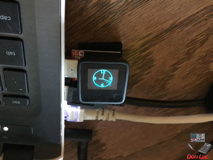
uView.begin(); // Begin of MicroView
uView.clear(ALL); // Erase hardware memory inside the OLED controller
uView.display(); // Display the content in the buffer memory, by default it is the MicroView logo
delay(1000);
uView.clear(PAGE); // Erase the memory buffer, the OLED will be cleared.
uView.setFontType(1); // Set font type 1: Numbers and letters. 7 characters per line (3 lines)
uView.setCursor(0,20);
uView.print("Don Luc"); // Don Luc
uView.display(); // Display
delay(5000);
uView.clear(PAGE); // Erase the memory buffer, the OLED will be cleared.
uView.setFontType(1); // Set font type 1: Numbers and letters. 7 characters per line (3 lines)
uView.setCursor(0,20);
uView.print("EMF Met"); // EMF Meter (Single Axis)
uView.display(); // Display
delay(5000);
uView.clear(PAGE); // Erase the memory buffer, the OLED will be cleared
// NeoPixels
pixels.begin(); // This initializes the NeoPixel library
// EMF Meter (Single Axis)
pinMode( iEMF, OUTPUT ); // EMF Meter
for (int i = 0; i < NUMREADINGS; i++){
readings[ i ] = 0; // Initialize all the readings to 0
}
// LED
pinMode( ledR, OUTPUT ); // LED Red
pinMode( ledG, OUTPUT ); // LED Green
pinMode( ledY, OUTPUT ); // LED Yellow
// LED Red - High
digitalWrite( ledR, HIGH);
}
Don Luc