
LowPowerLab: Moteino R2
What is Moteino?
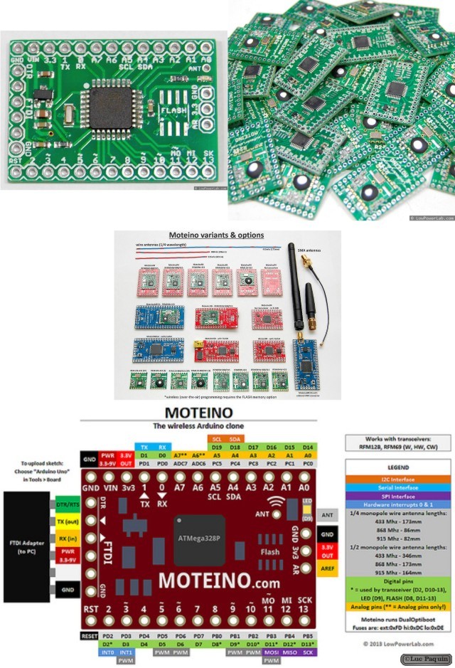
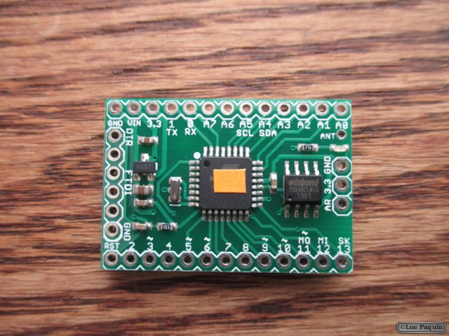
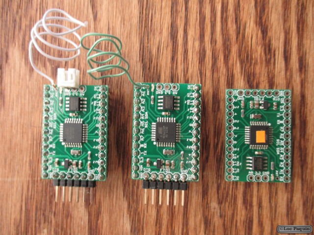
Moteino is a low cost low-power open-source wireless Arduino compatible development platform based on the popular ATMega328 chip used in traditional Arduinos, making it 100% compatible with the Arduino IDE (programming environment). Regular Moteino does not include an onboard USB-Serial converter (like traditional Arduinos), instead you need to use an external FTDI adapter to load sketches, the advantages being lower cost, smaller size. However there is a MoteinoUSB variant that the serial converter onboard. They are compatible with any other Arduino clones that use the popular HopeRF RFM69 transceiver, or the older RFM12B. Moteino also comes with an optional SPI flash memory chip for wireless programming, or data logging.
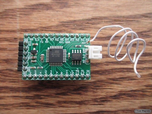
Soldering antenna and headers
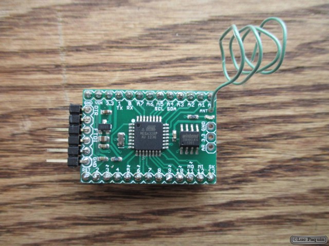
Moteinos come without any soldered headers or antennas. Without the wire antenna the range will be only a few feet, and while this is OK for testing purposes it’s recommended that an antenna be soldered before real application use of the transmitter. The provided wire monopole antenna has to be soldered to the “ANT” pin hole (just above the FLASH chip) to achieve any usable range. Regular Moteinos will come with a 1×6 male header that you have to solder before you can power it and upload sketches through an FTDI Adapter.
Specifications for Moteino R2
- Microcontroller: ATmega328
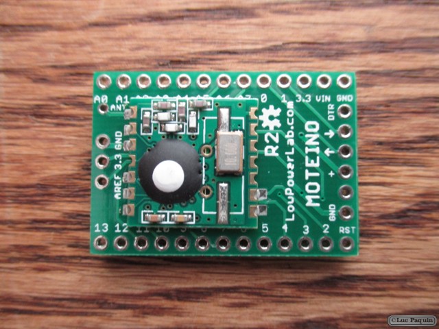
- Transceiver: RFM69 W/HW/CW, RFM12B
- Transceivers frequencies: 434Mhz, 868Mhz (EU), 915Mhz (US, Australia, etc.)
- Input Voltage: 3.5V-16V (up to 12V recommended)
- Operating Voltage: 3.3V (regulated by MCP1703 on most recent Moteinos)
- Digital I/O Pins: 14+6 (6 PWM capable: marked with “~” symbol)
- Analog Input Pins: 8 (2 analog-only pins more than regular Arduinos)
- DC Current per I/O Pin: 20 mA
- Flash Memory: 32 KB of which 1 KB used by DualOptiboot bootloader
- SRAM: 2 KB
- EEPROM: 1 KB
- Clock Speed: 16 MHz
MISC
- Onboard LED on pin D9 instead of D13 (D9 is PWM!)
- RFM12B or RFM69 SPI-CS on D10
- FLASH SPI-CS on D8
- A6 and A7 are analog pins only, cannot be used as digital pins
Don Luc