Projects
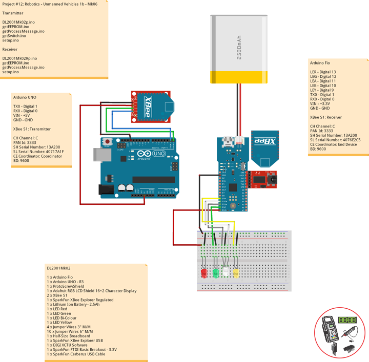
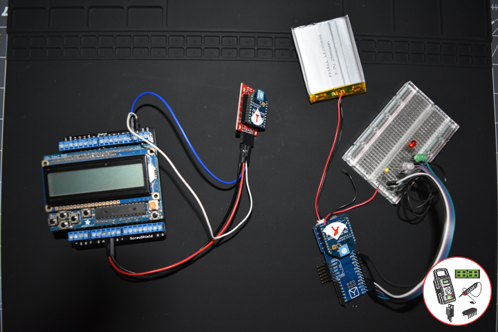
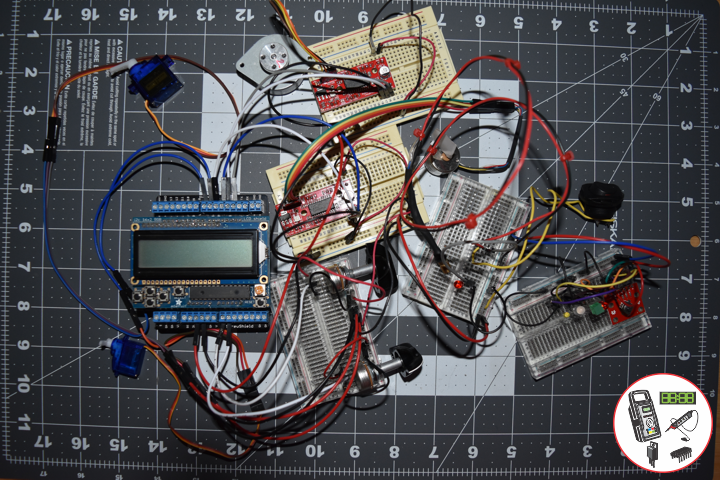
Project #12: Robotics – Unmanned Vehicles 1b – Mk06
——
——
——
——
——
XBee
Digi XBee is the brand name of a family of form factor compatible radio modules from Digi International. The first XBee radios were introduced under the MaxStream brand in 2005 and were based on the IEEE 802.15.4-2003 standard designed for point-to-point and star communications at over-the-air baud rates of 250 kbit/s.
Two models were initially introduced, a lower cost 1 mW XBee and the higher power 100 mW XBee-PRO. Since the initial introduction, a number of new XBee radios have been introduced and an ecosystem of wireless modules, gateways, adapters and software has evolved.
The XBee radios can all be used with the minimum number of connections — power (3.3 V), ground, data in and data out (UART), with other recommended lines being Reset and Sleep. Additionally, most XBee families have some other flow control, input/output (I/O), analog-to-digital converter (A/D) and indicator lines built in.
DL2001Mk02
1 x Arduino Fio
1 x Arduino UNO – R3
1 x ProtoScrewShield
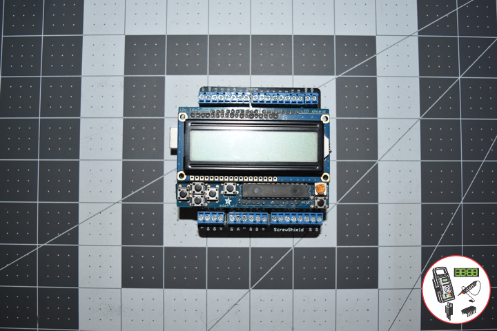
1 x Adafruit RGB LCD Shield 16×2 Character Display
2 x XBee S1
1 x SparkFun XBee Explorer Regulated
1 x Lithium Ion Battery – 2.5Ah
1 x LED Red
1 x LED Green
1 x LED Bi-Colour
1 x LED Yellow
4 x Jumper Wires 3″ M/M
10 x Jumper Wires 6″ M/M
1 x Half-Size Breadboard
1 x SparkFun XBee Explorer USB
1 x DIGI XCTU Software
1 x SparkFun FTDI Basic Breakout – 3.3V
1 x SparkFun Cerberus USB Cable
Arduino UNO
TX0 – Digital 1
RX0 – Digital 0
VIN – +5V
GND – GND
XBee S1: Transmitter
CH Channel: C
PAN Id: 3333
SH Serial Number: 13A200
SL Serial Number: 40717A1F
CE Coordinator: Coordinator
BD: 9600
DL2001Mk02p.ino
// ***** Don Luc Electronics © *****
// Software Version Information
// Project #12: Robotics - Unmanned Vehicles 1b - Mk06
// 01-02
// DL2001Mk01p.ino 12-06
// Arduino UNO - R3
// ProtoScrewShield
// Adafruit RGB LCD Shield 16×2 Character Display
// EEPROM with Unique ID
// Transmitter
// XBee S1
// Include the library code:
// EEPROM library to read and write EEPROM with unique ID for unit
#include <EEPROM.h>
// Adafruit RGB LCD Shield
#include <Adafruit_RGBLCDShield.h>
// Adafruit RGB LCD Shield
Adafruit_RGBLCDShield RGBLCDShield = Adafruit_RGBLCDShield();
// These #defines make it easy to set the backlight color
#define OFF 0x0
#define RED 0x1
#define YELLOW 0x3
#define GREEN 0x2
#define TEAL 0x6
#define BLUE 0x4
#define VIOLET 0x5
#define WHITE 0x7
// Momentary Button
int yy = 0;
uint8_t momentaryButton = 0;
// Communication
unsigned long dTime = 1000;
// The current address in the EEPROM (i.e. which byte we're going to read to next)
// Version
String sver = "12-2.p";
// Unit ID Information
String uid = "";
void loop() {
// Clear
RGBLCDShield.clear();
// set the cursor to column 0, line 0
RGBLCDShield.setCursor(0,0);
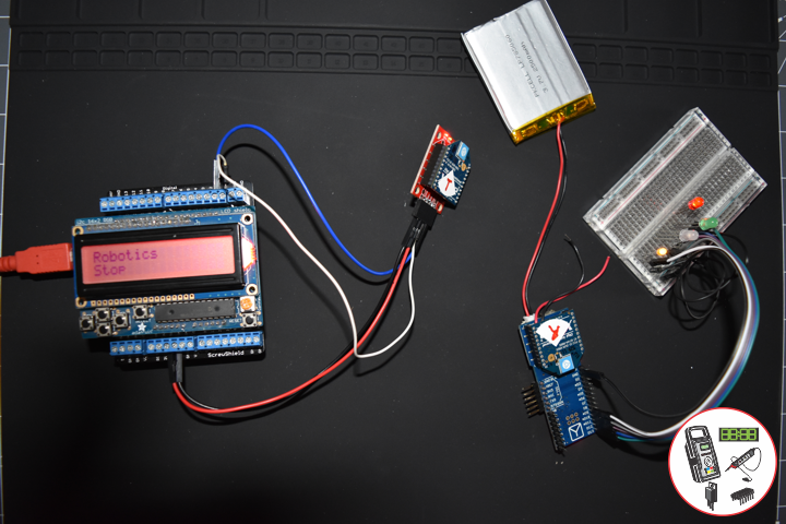
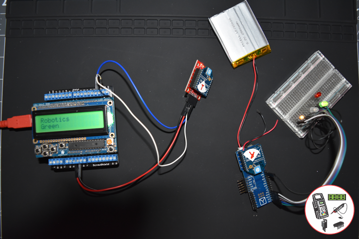
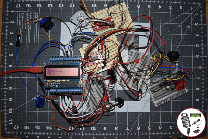
RGBLCDShield.print("Robotics"); // Robotics
// Momentary Button
momentaryButton = RGBLCDShield.readButtons();
switch ( yy ) {
case 1:
// LED Green
isSwitch1();
break;
case 2:
// LED Bipolar (Green)
isSwitch2();
break;
case 3:
// Right
isSwitch3();
break;
case 4:
// Left
isSwitch4();
break;
case 5:
// LED Red
isSwitch5();
break;
default:
// LED Red
yy = 5;
RGBLCDShield.setBacklight(RED);
isSwitch5();
}
if ( momentaryButton ) {
if ( momentaryButton & BUTTON_UP ) {
yy = 1;
// LED Green
RGBLCDShield.setBacklight(GREEN);
}
if ( momentaryButton & BUTTON_DOWN ) {
yy = 2;
// LED Bipolar A
RGBLCDShield.setBacklight(VIOLET);
}
if ( momentaryButton & BUTTON_LEFT ) {
yy = 3;
// LED Bipolar B
RGBLCDShield.setBacklight(TEAL);
}
if ( momentaryButton & BUTTON_RIGHT ) {
yy = 4;
// LED Bipolar A B
RGBLCDShield.setBacklight(YELLOW);
}
if ( momentaryButton & BUTTON_SELECT ) {
yy = 5;
// LED Red
RGBLCDShield.setBacklight(RED);
}
}
// Process Message
isProcessMessage();
delay( dTime );
}
getEEPROM.ino
// EEPROM
// isUID
void isUID()
{

  // Is Unit ID
  uid = "";
  for (int x = 0; x < 5; x++)
  {
    uid = uid + char(EEPROM.read(x));
  }

}
getProcessMessage.ino
// ProcessMessage
// isProcessMessage
void isProcessMessage() {

   //int incb = 0;
   String msg = "";

   /// Loop through serial buffer one byte at a time until you reach * which will be end of message
   //while ( Serial.available() )
  // {

      // Print => XBEE + Unit ID + Version + *
      msg = "XBEE|" + uid + "|" + sver + "|" + yy + "|*";
      Serial.println( msg );

  // }

}
getSwitch.ino
// Switch
// Switch 1
void isSwitch1(){

   yy = 1;

   isSwitchLEDStop();
   // LED
   // turn LED on:
   RGBLCDShield.setCursor(0,1);
   RGBLCDShield.print("Green");

}
// Switch 2
void isSwitch2(){

   yy = 2;

   isSwitchLEDStop();
   // LED
   // turn LED on:
   RGBLCDShield.setCursor(0,1);
   RGBLCDShield.print("Bi-Colour A");

}
// Switch 3
void isSwitch3(){

   yy = 3;

   isSwitchLEDStop();
   // LED
   // turn LED on:
   RGBLCDShield.setCursor(0,1);
   RGBLCDShield.print("Bi-Colour B");

}
// Switch 4
void isSwitch4(){

   yy = 4;

   isSwitchLEDStop();
   // LED
   // turn LED on:
   RGBLCDShield.setCursor(0,1);
   RGBLCDShield.print("Bi-Colour A B");

}
// Switch 5
void isSwitch5(){

   yy = 5;

   RGBLCDShield.setCursor(0,1);
   RGBLCDShield.print("Stop");

   //delay( 250 );

   isSwitchLEDStop();
   // LED
   // turn LED on:
   //digitalWrite(iLEDRed, HIGH);

}
void isSwitchLEDStop(){

  //digitalWrite(iLEDRed, LOW);
  //digitalWrite(iLEDGreen, LOW);
  //digitalWrite(iLEDB1, LOW);
  //digitalWrite(iLEDB2, LOW);
  //digitalWrite(iLEDYellow, LOW);

}
setup.ino
// Setup
void setup() {

  //Open serial port at 9600 baud
  Serial.begin( 9600 );

  // Pause
  delay(5);

  // EEPROM Unit ID
  isUID();

  // Pause
  delay(5);

  // Adafruit RGB LCD Shield
  // Set up the LCD's number of columns and rows:
  RGBLCDShield.begin(16, 2);
  RGBLCDShield.setBacklight(GREEN);

  // Display
  // Set the cursor to column 0, line 0
  RGBLCDShield.setCursor(0,0);
  RGBLCDShield.print("Don Luc Electron");         // Don luc Electron
  // Set the cursor to column 0, line 1
  RGBLCDShield.setCursor(0, 1);
  RGBLCDShield.print("Robotics");                 // Robotics

  // Serial
  Serial.println( "Don Luc Electronics");
  Serial.println( "Robotics");

  delay(5000);

  // Clear
  RGBLCDShield.clear();

  // Display
  // Set the cursor to column 0, line 0
  RGBLCDShield.setCursor(0,0);
  RGBLCDShield.print("Version: ");                // Version
  RGBLCDShield.print( sver );
  // Set the cursor to column 0, line 1
  RGBLCDShield.setCursor(0, 1);
  RGBLCDShield.print("UID: ");                    // Unit ID Information
  RGBLCDShield.print( uid );

  // Serial
  Serial.print( "Software Version Information: ");
  Serial.println( sver );
  Serial.print( "Unit ID Information: ");
  Serial.println( uid );

  delay(5000);

  // Clear
  RGBLCDShield.clear();

}
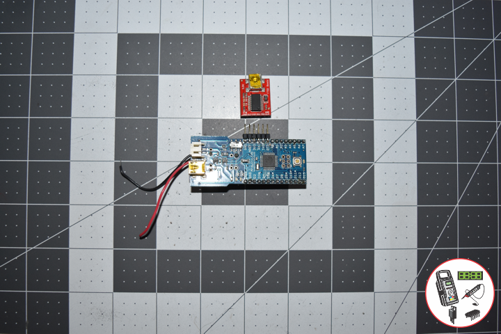
Arduino Fio
LER – Digital 13
LEG – Digital 12
LEA – Digital 11
LEB – Digital 10
LEY – Digital 9
TX0 – Digital 1
RX0 – Digital 0
VIN – +3.3V
GND – GND
XBee S1: Receiver
CH Channel: C
PAN Id: 3333
SH Serial Number: 13A200
SL Serial Number: 4076E2C5
CE Coordinator: End Device
BD: 9600
DL2001Mk02Rp.ino
// ***** Don Luc Electronics © *****
// Software Version Information
// Project #12: Robotics - Unmanned Vehicles 1b - Mk06
// 01-02
// DL2001Mk02Rp.ino 12-06
// Arduino Fio
// SparkFun FTDI Basic Breakout - 3.3V
// EEPROM with Unique ID
// LED Red
// LED Green
// LED Bi-Colour
// LED Yellow
// Lithium Ion Battery - 2.5Ah
// Receiver
// XBee S1

// Include the library code:
// EEPROM library to read and write EEPROM with unique ID for unit
#include <EEPROM.h>

// LED Red
int iLEDRed = 13;
// LED Green
int iLEDGreen = 12;
// LED Bi-Colour
int iLEDBiCoA = 11;
int iLEDBiCoB = 10;
// LED Yellow
int iLEDYellow = 9;

// Momentary Button
int yy = "";

// Software Version Information
String sver = "12-02";
// Unit ID information
String uid = "DR001";

void loop() {

  // Check for serial messages
  if ( Serial.available() )
  {
    isProcessMessage();
  }

  // Switch
  isSwitch();

}
getEEPROM.ino
// EEPROM
// isUID
void isUID()
{

  // Is Unit ID
  uid = "";
  for (int x = 0; x < 5; x++)
  {
    uid = uid + char(EEPROM.read(x));
  }

}
getProcessMessage.ino
// ProcessMessage
// isProcessMessage
void isProcessMessage() {

   int incb = 0;
   String msg = "";
   String zzz = "";

  // Loop through serial buffer one byte at a time until you reach * which will be end of message
  while ( Serial.available() )
  {

      // Read the incoming byte:
      incb = Serial.read();
      // Add character to string
      msg = msg + char(incb);

      // Check if receive character is the end of message *
      if ( incb == 42 )
      {

         Serial.println(msg);

         zzz = msg.charAt( 18 );

         Serial.println(zzz);

         yy = zzz.toInt();

        Serial.println( yy );

      }
   }

}
getSwitch.ino
// Switch
// isSwitch
void isSwitch(){

  switch ( yy ) {
    case 1:

      // LED Green
      sLEDStop();
      digitalWrite(iLEDGreen, HIGH);
      delay( 1000 );

      break;
    case 2:

      // LED Bi-Colour A
      sLEDStop();
      digitalWrite(iLEDBiCoA, HIGH);
      delay( 1000 );

      break;
    case 3:

      // LED Bi-Colour B
      sLEDStop();
      digitalWrite(iLEDBiCoB, HIGH);
      delay( 1000 );

      break;
    case 4:

      // LED Bi-Colour A B
      sLEDStop();
      digitalWrite(iLEDBiCoA, HIGH);
      digitalWrite(iLEDBiCoB, HIGH);
      delay( 1000 );

      break;
    case 5:

      // LED Red
      sLEDStop();
      digitalWrite(iLEDRed, HIGH);
      delay( 1000 );

      break;
    default:

      // LED Red
      sLEDStop();
      digitalWrite(iLEDRed, HIGH);
      delay( 1000 );

   }

}
// LED Stop
void sLEDStop(){

  digitalWrite(iLEDRed, LOW);
  digitalWrite(iLEDGreen, LOW);
  digitalWrite(iLEDBiCoA, LOW);
  digitalWrite(iLEDBiCoB, LOW);

}
setup.ino
// Setup
void setup() {

  // Open the serial port at 9600 bps:
  Serial.begin( 9600 );

  // Pause
  delay(5);

  // EEPROM Unit ID
  isUID();

  // Pause
  delay(5);

  // Serial
  Serial.print( "Software Version Information: ");
  Serial.println( sver );
  Serial.print( "Unit ID Information: ");
  Serial.println( uid );

  delay(5000);

  // LED => OUTPUT
  pinMode(iLEDRed, OUTPUT);
  pinMode(iLEDGreen, OUTPUT);
  pinMode(iLEDBiCoA, OUTPUT);
  pinMode(iLEDBiCoB, OUTPUT);
  pinMode(iLEDYellow, OUTPUT);

  // LED Yellow
  digitalWrite(iLEDYellow, HIGH);

}
Follow Us
J. Luc Paquin – Curriculum Vitae
https://www.donluc.com/DLHackster/LucPaquinCVEngMk2020a.pdf
Web: https://www.donluc.com/
Web: http://www.jlpconsultants.com/
Web: https://www.donluc.com/DLHackster/
Web: https://www.hackster.io/neosteam-labs
Web: http://neosteamlabs.com/
YouTube: https://www.youtube.com/channel/UC5eRjrGn1CqkkGfZy0jxEdA
Facebook: https://www.facebook.com/neosteam.labs.9/
Instagram: https://www.instagram.com/neosteamlabs/
Pinterest: https://www.pinterest.com/NeoSteamLabs/
Twitter: https://twitter.com/labs_steam
Etsy: https://www.etsy.com/shop/NeoSteamLabs
Don Luc
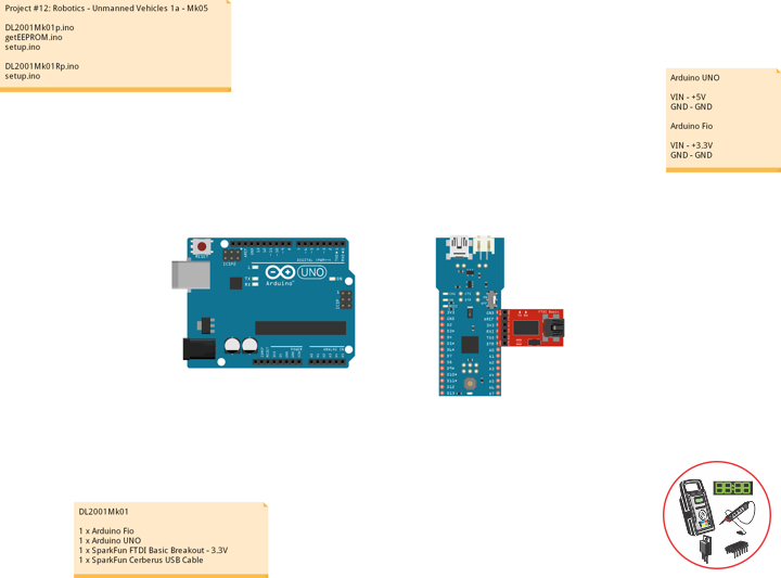
Project #12: Robotics – Unmanned Vehicles 1a – Mk05
——
——
——
——
——
——
——
EEPROM
EEPROM stands for electrically erasable programmable read-only memory and is a type of non-volatile memory used in computers, integrated in microcontrollers for smart cards and remote keyless systems, and other electronic devices to store relatively small amounts of data but allowing individual bytes to be erased and reprogrammed.
Transmitter
In electronics and telecommunications a transmitter or radio transmitter is an electronic device which produces radio waves with an antenna. The transmitter itself generates a radio frequency alternating current, which is applied to the antenna. When excited by this alternating current, the antenna radiates radio waves.
Receiver
A modern communications receiver, used in two-way radio communication stations to talk with remote locations by shortwave radio.
In radio communications, a radio receiver, also known as a receiver, wireless or simply radio is an electronic device that receives radio waves and converts the information carried by them to a usable form. It is used with an antenna. The antenna intercepts radio waves (electromagnetic waves) and converts them to tiny alternating currents which are applied to the receiver, and the receiver extracts the desired information.
DL2001Mk01
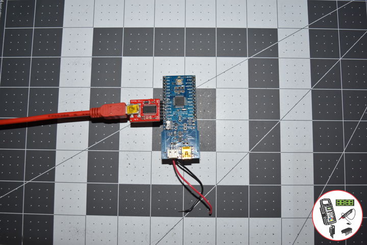
1 x Arduino Fio
1 x Arduino UNO
1 x SparkFun FTDI Basic Breakout – 3.3V
1 x SparkFun Cerberus USB Cable
Arduino UNO
VIN – +5V
GND – GND
Arduino Fio
VIN – +3.3V
GND – GND
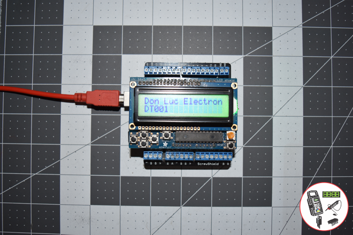
Transmitter => DT001
DL2001Mk01p.ino
// ***** Don Luc Electronics © *****
// Software Version Information
// Project #12: Robotics - Unmanned Vehicles 1a - Mk05
// 01-01
// DL2001Mk01p.ino 12-05
// Arduino UNO
// Screw Shield
// Adafruit RGB LCD Shield
// EEPROM with Unique ID
// Transmitter
// Include the library code:
#include <Adafruit_RGBLCDShield.h>
// EEPROM library to read and write EEPROM with unique ID for unit
#include <EEPROM.h>
// Adafruit RGB LCD Shield
Adafruit_RGBLCDShield RGBLCDShield = Adafruit_RGBLCDShield();
// These #defines make it easy to set the backlight color
#define GREEN 0x2
// Momentary Button
int yy = 0;
uint8_t momentaryButton = 0;
// Software Version Information
String sver = "12-05";
// Unit ID Information
String uid = "DT001";
void loop() {
// Display
// Set the cursor to column 0, line 0
RGBLCDShield.setCursor(0,0);
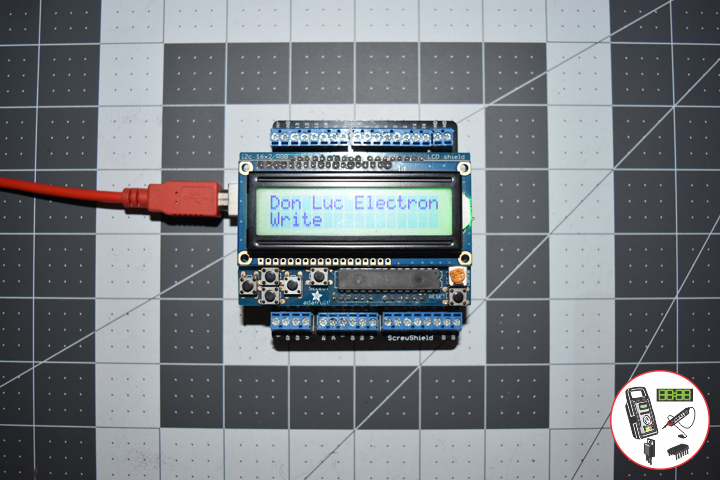
RGBLCDShield.print("Don Luc Electron"); // Don luc Electron
momentaryButton = RGBLCDShield.readButtons();
if ( momentaryButton ) {
if ( momentaryButton & BUTTON_UP ) {
isEEPROMw();
yy = 1;
}
if ( momentaryButton & BUTTON_DOWN ) {
isUID();
yy = 2;
}
if ( momentaryButton & BUTTON_LEFT ) {
UIDr();
yy =3;
}
if ( momentaryButton & BUTTON_RIGHT ) {
isEEPROMc();
yy = 4;
}
}
delay(1000);
// Clear
RGBLCDShield.clear();
}
getEEPROM.ino
// getEEPROM
// Write and Read EEPROM with Unique ID for Unit
// Write EEPROM with Unique ID for Unit
void isEEPROMw() {

  // set the cursor to column 0, line 1
  RGBLCDShield.setCursor(0, 1);
  RGBLCDShield.print( "Write" );

  // EEPROM
  int incb = 0;
  int v = 0;
  String msg = "";
  String emp = "";

  // Set Unit ID
  // The message starts with sid then is followed by 5 characters
  // First clear a string buffer
  emp = "";
  // Loop through the 5 ID characters and write their ASCII (byte) value to the EEPROM
  for (int x = 0; x < 5; x++)
    {
       //Get ASCII value of character
       v = int(uid.charAt(x)); // + 5));
       //Add the actual character to the buffer so we can send it back to the PC
       emp = emp + uid.charAt(x + 5);
       //Write the value to the EEPROM
       EEPROM.write(x, v);
    }

   delay( 5000 );

}
// Read EEPROM with Unique ID for Unit
void isUID()
{
  // Unit ID
  String ruid = "";
  for (int x = 0; x < 5; x++)
  {
    ruid = ruid + char(EEPROM.read(x));
  }

  // set the cursor to column 0, line 1
  RGBLCDShield.setCursor(0, 1);
  RGBLCDShield.print( ruid );

  delay( 5000 );

}
// Read uid
void UIDr()
{

   // set the cursor to column 0, line 1
   RGBLCDShield.setCursor(0, 1);
   RGBLCDShield.print( uid );

   delay( 5000 );

}
// Clear EEPROM
void isEEPROMc()
{

   // Clear EEPROM
   for (int i = 0 ; i < EEPROM.length() ; i++) {
      EEPROM.write(i, 0);
   }

   // set the cursor to column 0, line 1
   RGBLCDShield.setCursor(0, 1);
   RGBLCDShield.print( "Clear EEPROM" );

   delay( 5000 );

}
setup.ino
// Setup
void setup() {

  // Adafruit RGB LCD Shield
  // Set up the LCD's number of columns and rows:
  RGBLCDShield.begin(16, 2);
  RGBLCDShield.setBacklight(GREEN);

  // Display
  // Set the cursor to column 0, line 0
  RGBLCDShield.setCursor(0,0);
  RGBLCDShield.print("Don Luc Electron");         // Don luc Electron
  // Set the cursor to column 0, line 1
  RGBLCDShield.setCursor(0, 1);
  RGBLCDShield.print("Unique ID");                // Unique ID

  delay(5000);

  // Clear
  RGBLCDShield.clear();

}
Receiver => DR001
DL2001Mk01Rp.ino
// ***** Don Luc Electronics © *****
// Software Version Information
// Project #12: Robotics - Unmanned Vehicles 1a - Mk05
// 01-01
// DL2001Mk01Rp.ino 12-05
// Arduino Fio
// SparkFun FTDI Basic Breakout - 3.3V
// EEPROM with Unique ID
// Receiver

// Include the library code:
// EEPROM library to read and write EEPROM with unique ID for unit
#include <EEPROM.h>

// Software Version Information
String sver = "12-05";
// Unit ID information
String uid = "DR001";

void loop() {

  // Write EEPROM with Unique ID for Unit
  int incb = 0;
  int v = 0;
  String emp = "";
  String ruid = "";

  // Set Unit ID
  // The message starts with uid then is followed by 5 characters
  // First clear a string buffer
  emp = "";
  // Loop through the 5 ID characters and write their ASCII (byte) value to the EEPROM
  for (int y = 0; y < 5; y++)
  {

     // Get ASCII value of character
     v = int(uid.charAt(y)); // + 5));
     // Add the actual character to the buffer
     emp = emp + uid.charAt(y + 5);
     // Write the value to the EEPROM
     EEPROM.write(y, v);

  }

  // Write EEPROM with Unique ID for Unit
  Serial.println( "Write ID Information");

  // Read ID Information
  // Unit ID
  for (int y = 0; y < 5; y++)
  {

    ruid = ruid + char(EEPROM.read(y));

  }

  // Read ID Information
  Serial.print( "Read ID Information: ");
  Serial.println( ruid );
  Serial.println( "Ok!" );
  ruid = "";

  delay( 5000 );

}
setup.ino
// Setup
void setup() {

  // Open the serial port at 9600 bps:
  Serial.begin(9600);

  // Serial
  Serial.print( "Software Version Information: ");
  Serial.println( sver );
  Serial.print( "Unit ID Information: ");
  Serial.println( uid );

  delay(5000);

}
Follow Us
J. Luc Paquin – Curriculum Vitae
https://www.donluc.com/DLHackster/LucPaquinCVEngMk2020a.pdf
Web: https://www.donluc.com/
Web: http://www.jlpconsultants.com/
Web: https://www.donluc.com/DLHackster/
Web: https://www.hackster.io/neosteam-labs
Web: http://neosteamlabs.com/
YouTube: https://www.youtube.com/channel/UC5eRjrGn1CqkkGfZy0jxEdA
Facebook: https://www.facebook.com/neosteam.labs.9/
Instagram: https://www.instagram.com/neosteamlabs/
Pinterest: https://www.pinterest.com/NeoSteamLabs/
Twitter: https://twitter.com/labs_steam
Etsy: https://www.etsy.com/shop/NeoSteamLabs
Don Luc
Project #12: Robotics – 5-Way Switch – Mk04
——
——
——
——
——
——
——
SparkFun 5-Way Tactile Switch Breakout
This 5-way tactile switch (up, down, left, right, and center click) allows for joystick-like control in a very small package.
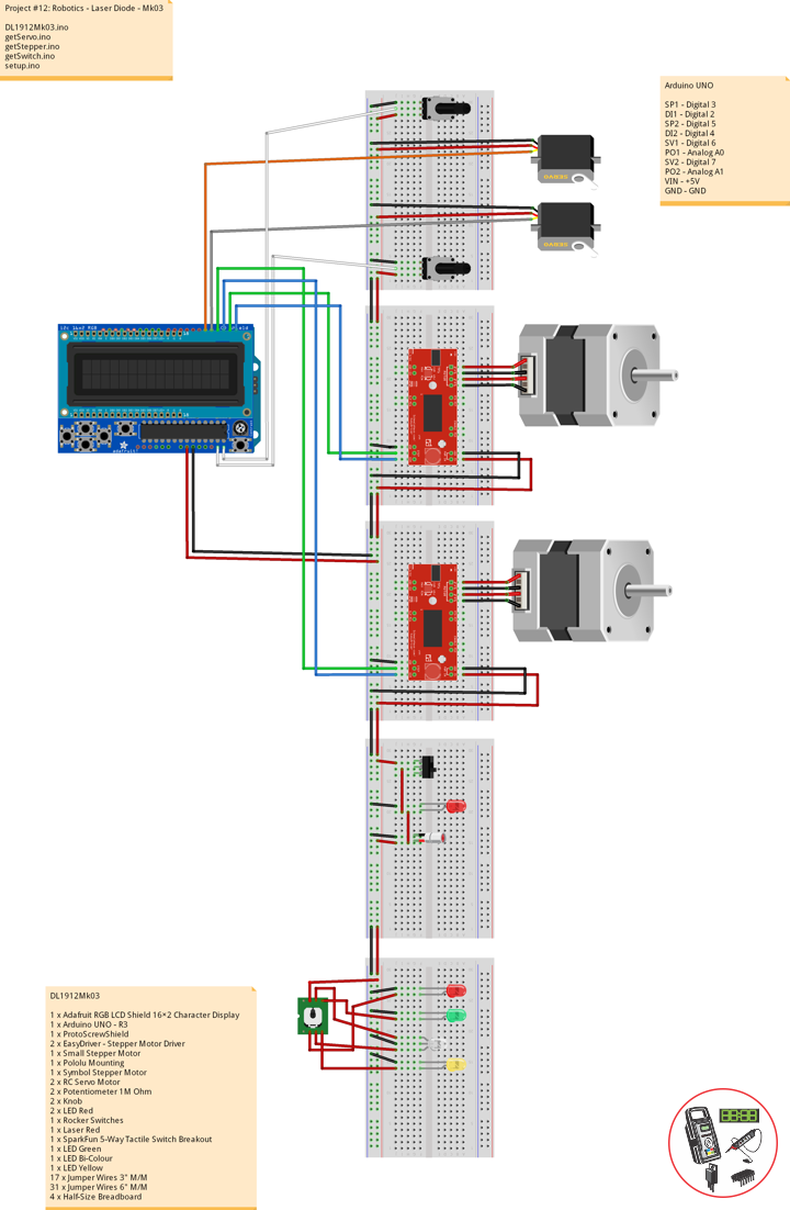
DL1912Mk03
1 x Adafruit RGB LCD Shield 16×2 Character Display
1 x Arduino UNO – R3
1 x ProtoScrewShield
2 x EasyDriver – Stepper Motor Driver
1 x Small Stepper Motor
1 x Pololu Mounting
1 x Symbol Stepper Motor
2 x RC Servo Motor
2 x Potentiometer 1M Ohm
2 x Knob
2 x LED Red
1 x Rocker Switches
1 x Laser Red
1 x SparkFun 5-Way Tactile Switch Breakout
1 x LED Green
1 x LED Bi-Colour
1 x LED Yellow
17 x Jumper Wires 3″ M/M
31 x Jumper Wires 6″ M/M
4 x Half-Size Breadboard
Arduino UNO
SP1 – Digital 3
DI1 – Digital 2
SP2 – Digital 5
DI2 – Digital 4
SV1 – Digital 6
PO1 – Analog A0
SV2 – Digital 7
PO2 – Analog A1
VIN – +5V
GND – GND
DL1912Mk03.ino
// ***** Don Luc Electronics © *****
// Software Version Information
// Project #12: Robotics - 5-Way Switch - Mk04
// 12-03
// DL1912Mk02p.ino 12-04
// Arduino UNO
// Screw Shield
// Adafruit RGB LCD Shield
// 1 x Small Stepper Motor
// 1 x Symbol Stepper Motor
// 2 x EasyDriver
// 2 x RC Servo Motor
// 2 x Potentiometer
// 2 x LED Red
// 1 x Rocker Switches
// 1 x Laser Red
// 1 x SparkFun 5-Way Tactile Switch Breakout
// 1 x LED Green
// 1 x LED Bi-Colour
// 1 x LED Yellow

// include the library code:
#include <Adafruit_RGBLCDShield.h>
#include <Servo.h>

// Adafruit RGB LCD Shield
Adafruit_RGBLCDShield RGBLCDShield = Adafruit_RGBLCDShield();

// These #defines make it easy to set the backlight color
#define OFF 0x0
#define RED 0x1
#define YELLOW 0x3
#define GREEN 0x2
#define TEAL 0x6
#define BLUE 0x4
#define VIOLET 0x5
#define WHITE 0x7

// Momentary Button
int yy = 0;
uint8_t momentaryButton = 0;

// 2 x EasyDriver
int dirPinR = 2;                           // EasyDriver Right
int stepPinR = 3;                          // stepPin Right
int dirPinL = 4;                           // EasyDriver Left
int stepPinL = 5;                          // stepPin Left
int i = 0;

// 2 x RC Servo Motor
// 2 x Potentiometer
Servo isRCServo1;                          // Create servo object to control a RCServo1
int servo1 = 6;                            // Servo 1
int iPot1 = A0;                            // Analog Potentiometer 1
int iVal1;                                 // Variable - Analog Potentiometer 1
Servo isRCServo2;                          // Create servo object to control a RCServo2
int servo2 = 7;                            // Servo 2
int iPot2 = A1;                            // Analog Potentiometer 2
int iVal2;                                 // Variable - Analog Potentiometer 2

void loop() {

  // Clear
  RGBLCDShield.clear();

  // Momentary Button
  momentaryButton = RGBLCDShield.readButtons();

  switch ( yy ) {
    case 1:

      // Up
      isSwitch1();

      break;
    case 2:

      // Down
      isSwitch2();

      break;
    case 3:

      // Right
      isSwitch3();

      break;
    case 4:

      // Left
      isSwitch4();

      break;
    case 5:

      // Stop
      isSwitch5();

      break;
    default:

      // Stop
      yy = 5;
      RGBLCDShield.setBacklight(RED);
      isSwitch5();

   }

   if ( momentaryButton ) {

    if ( momentaryButton & BUTTON_UP ) {

      yy = 1;
      // Up
      RGBLCDShield.setBacklight(GREEN);

    }

    if ( momentaryButton & BUTTON_DOWN ) {

      yy = 2;
      // Down
      RGBLCDShield.setBacklight(VIOLET);

    }

    if ( momentaryButton & BUTTON_LEFT ) {

      yy = 3;
      // Right
      RGBLCDShield.setBacklight(TEAL);

    }

    if ( momentaryButton & BUTTON_RIGHT ) {

      yy = 4;
      // Left
      RGBLCDShield.setBacklight(YELLOW);
    }

    if ( momentaryButton & BUTTON_SELECT ) {

      yy = 5;
      // Stop
      RGBLCDShield.setBacklight(RED);

    }

  }

}
getServo.ino
// Servo
// isServoSetup
void isServoSetup() {

  // 2 x RC Servo Motor
  isRCServo1.attach( servo1 );
  isRCServo2.attach( servo2 );

}
// isServo1
void isServo1() {

  // EasyDriver
  isStepperStop();

  // Potentiometer RC Servo Motor 1
  iVal1 = analogRead( iPot1 );              // Reads the value of the iPot1 (Value between 0 and 1023)
  iVal1 = map(iVal1, 0, 1023, 0, 180);      // Scale it to use it with the isRCServo1 (Value between 0 and 180)
  isRCServo1.write( iVal1 );                // isRCServo1 sets the servo position according to the scaled value
  delay(15);

  // Display
  // Set the cursor to column 0, line 0
  RGBLCDShield.setCursor(0,0);
  RGBLCDShield.print("RC Servo 1");         // RC Servo 1
  // Set the cursor to column 0, line 1
  RGBLCDShield.setCursor(0, 1);
  RGBLCDShield.print( iVal1 );              // Reads the value iVal1

  delay(500);

}
// isServo2
void isServo2() {

  // EasyDriver
  isStepperStop();

  // Potentiometer RC Servo Motor 1
  iVal2 = analogRead( iPot2 );              // Reads the value of the iPot2 (Value between 0 and 1023)
  iVal2 = map(iVal2, 0, 1023, 0, 180);      // Scale it to use it with the isRCServo2 (Value between 0 and 180)
  isRCServo2.write( iVal2 );                // isRCServo2 sets the servo position according to the scaled value
  delay(15);

  // Display
  // Set the cursor to column 0, line 0
  RGBLCDShield.setCursor(0,0);
  RGBLCDShield.print("RC Servo 2");         // RC Servo 2
  // Set the cursor to column 0, line 1
  RGBLCDShield.setCursor(0, 1);
  RGBLCDShield.print( iVal2 );              // Reads the value iVal2

  delay(500);

}
getStepper.ino
// Stepper
// isStepperSetup
void isStepperSetup() {
// 2 x EasyDriver
pinMode(dirPinR, OUTPUT);
pinMode(stepPinR, OUTPUT);
pinMode(dirPinL, OUTPUT);
pinMode(stepPinL, OUTPUT);
}
// isStepper1
void isStepper1(){
// set the cursor to column 0, line 0
RGBLCDShield.setCursor(0,0);
RGBLCDShield.print("EasyDriver"); // EasyDriver
RGBLCDShield.setCursor(0,1);
RGBLCDShield.print("Small Stepper"); // Small Stepper
delay(500);
// EasyDriver
digitalWrite(dirPinR, LOW); // Set the direction.
delay(100);
for (i = 0; i<300; i++) // Iterate for 1000 microsteps.
{
digitalWrite(stepPinR, LOW); // This LOW to HIGH change is what creates the
digitalWrite(stepPinR, HIGH); // "Rising Edge" so the easydriver knows to when to step.
delayMicroseconds(170); // This delay time is close to top speed.
}
}
// isStepper2
void isStepper2(){
// set the cursor to column 0, line 0
RGBLCDShield.setCursor(0,0);
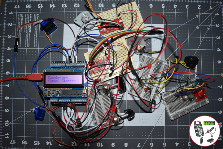
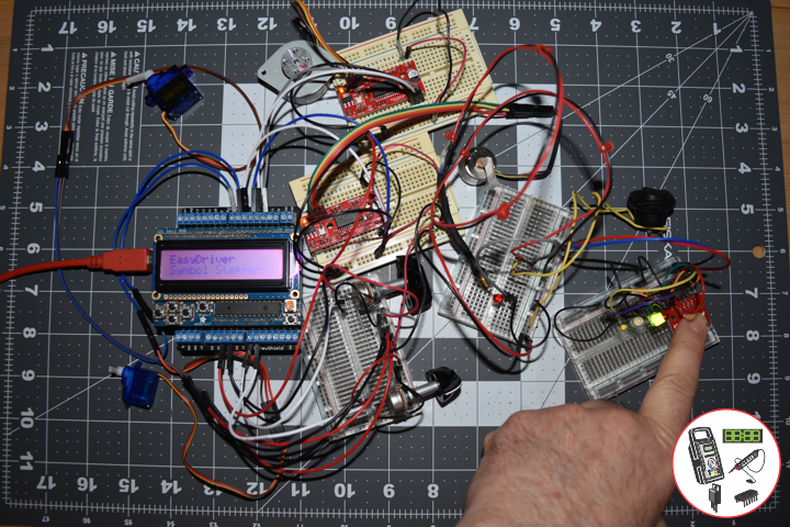
RGBLCDShield.print("EasyDriver"); // EasyDriver
RGBLCDShield.setCursor(0,1);
RGBLCDShield.print("Symbol Stepper"); // Symbol Stepper
delay(500);
// EasyDriver
digitalWrite(dirPinL, HIGH); // Set the direction.
delay(100);
for (i = 0; i<300; i++) // Iterate for 1000 microsteps.
{
digitalWrite(stepPinL, LOW); // This LOW to HIGH change is what creates the
digitalWrite(stepPinL, HIGH); // "Rising Edge" so the easydriver knows to when to step.
delayMicroseconds(170); // This delay time is close to top speed.
}
}
// isStepperStop
void isStepperStop() {
// 2 x EasyDriver
digitalWrite(dirPinR, LOW); // Set the direction.
delay(100);
digitalWrite(dirPinL, LOW); // Set the direction.
delay(100);
digitalWrite(stepPinR, LOW); // This LOW to HIGH change is what creates the
digitalWrite(stepPinL, LOW); // This LOW to HIGH change is what creates the
}
getSwitch.ino
// Switch
// Switch 1
void isSwitch1(){
// Small Stepper
yy = 1;
// EasyDriver
isStepper1();
}
// Switch 2
void isSwitch2(){
// Symbol Stepper
yy = 2;
// EasyDriver
isStepper2();
}
// Switch 3
void isSwitch3(){
// RC Servo Motor 1
yy = 3;
// Potentiometer RC Servo Motor 1
isServo1();
}
// Switch 4
void isSwitch4(){
// RC Servo Motor 2
yy = 4;
// Potentiometer RC Servo Motor 2
isServo2();
}
// Switch 5
void isSwitch5(){
// Stop
yy = 5;
// set the cursor to column 0, line 0
RGBLCDShield.setCursor(0,0);
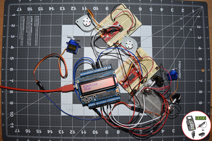
RGBLCDShield.print("Robotics"); // Robotics
RGBLCDShield.setCursor(0,1);
RGBLCDShield.print("Stop");
delay( 500 );
// EasyDriver
isStepperStop();
}
setup.ino
// Setup
void setup() {

  // Adafruit RGB LCD Shield
  // Set up the LCD's number of columns and rows:
  RGBLCDShield.begin(16, 2);
  RGBLCDShield.setBacklight(GREEN);

  // Display
  // Set the cursor to column 0, line 0
  RGBLCDShield.setCursor(0,0);
  RGBLCDShield.print("Don Luc Electron");         // Don luc Electron
  // Set the cursor to column 0, line 1
  RGBLCDShield.setCursor(0, 1);
  RGBLCDShield.print("Robotics");                // EasyDriver

  delay(5000);

  // Clear
  RGBLCDShield.clear();

  // 2 x EasyDriver
  isStepperSetup();

  // 2 x RC Servo Motor
  isServoSetup();

}
Follow Us
Web: https://www.donluc.com/
Web: http://www.jlpconsultants.com/
Web: https://www.donluc.com/DLHackster/
Web: https://www.hackster.io/neosteam-labs
Web: http://neosteamlabs.com/
YouTube: https://www.youtube.com/channel/UC5eRjrGn1CqkkGfZy0jxEdA
Facebook: https://www.facebook.com/neosteam.labs.9/
Instagram: https://www.instagram.com/neosteamlabs/
Pinterest: https://www.pinterest.com/NeoSteamLabs/
Twitter: https://twitter.com/labs_steam
Etsy: https://www.etsy.com/shop/NeoSteamLabs
Don Luc
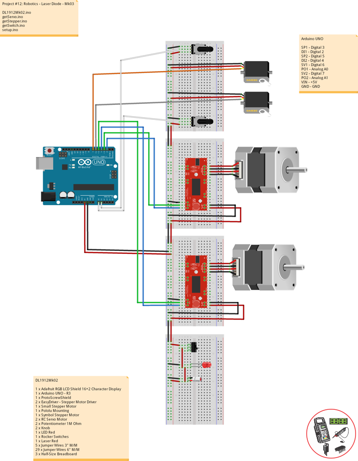
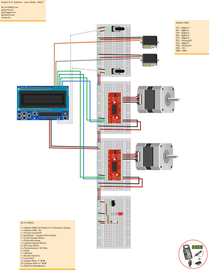
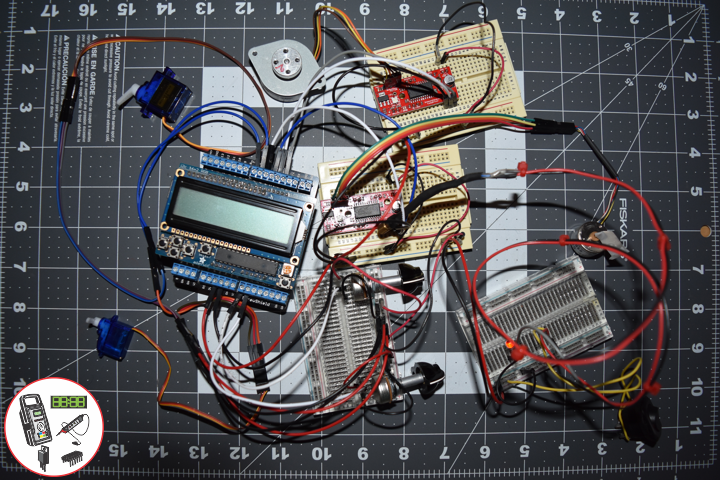
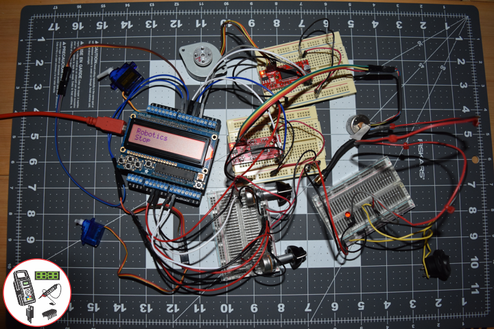
Project #12: Robotics – Laser Diode – Mk03
——
——
——
——
——
——
Laser Diode
A laser diode is a semiconductor device similar to a light-emitting diode in which a diode pumped directly with electrical current can create lasing conditions at the diode’s junction. Laser diodes can directly convert electrical energy into light. Due to the drop of the electron from a higher energy level to a lower one, radiation, in the form of an emitted photon is generated. This is spontaneous emission. Stimulated emission can be produced when the process is continued and further generate light with the same phase, coherence and wavelength.
The choice of the semiconductor material determines the wavelength of the emitted beam, which in today’s laser diodes range from infra-red to the UV spectrum. Laser diodes are the most common type of lasers produced, with a wide range of uses that include fiber optic communications, barcode readers, laser pointers, CD/DVD/Blu-ray disc reading/recording, laser printing, laser scanning and light beam illumination. With the use of a phosphor like that found on white LEDs, Laser diodes can be used for general illumination.
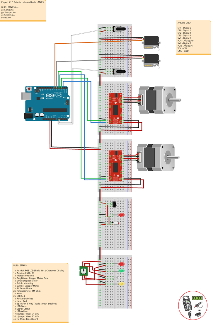
DL1912Mk02
1 x Adafruit RGB LCD Shield 16×2 Character Display
1 x Arduino UNO – R3
1 x ProtoScrewShield
2 x EasyDriver – Stepper Motor Driver
1 x Small Stepper Motor
1 x Pololu Mounting
1 x Symbol Stepper Motor
2 x RC Servo Motor
2 x Potentiometer 1M Ohm
2 x Knob
1 x LED Red
1 x Rocker Switches
1 x Laser Red
5 x Jumper Wires 3″ M/M
29 x Jumper Wires 6″ M/M
3 x Half-Size Breadboard
Arduino UNO
SP1 – Digital 3
DI1 – Digital 2
SP2 – Digital 5
DI2 – Digital 4
SV1 – Digital 6
PO1 – Analog A0
SV2 – Digital 7
PO2 – Analog A1
VIN – +5V
GND – GND
DL1912Mk02.ino
// ***** Don Luc Electronics © *****
// Software Version Information
// Project #12: Robotics - Laser Diode - Mk03
// 12-02
// DL1912Mk02p.ino 12-03
// Arduino UNO
// Screw Shield
// Adafruit RGB LCD Shield
// 1 x Small Stepper Motor
// 1 x Symbol Stepper Motor
// 2 x EasyDriver
// 2 x RC Servo Motor
// 2 x Potentiometer
// 1 x LED Red
// 1 x Rocker Switches
// 1 x Laser Red

// include the library code:
#include <Adafruit_RGBLCDShield.h>
#include <Servo.h>

// Adafruit RGB LCD Shield
Adafruit_RGBLCDShield RGBLCDShield = Adafruit_RGBLCDShield();

// These #defines make it easy to set the backlight color
#define OFF 0x0
#define RED 0x1
#define YELLOW 0x3
#define GREEN 0x2
#define TEAL 0x6
#define BLUE 0x4
#define VIOLET 0x5
#define WHITE 0x7

// Momentary Button
int yy = 0;
uint8_t momentaryButton = 0;

// 2 x EasyDriver
int dirPinR = 2;                           // EasyDriver Right
int stepPinR = 3;                          // stepPin Right
int dirPinL = 4;                           // EasyDriver Left
int stepPinL = 5;                          // stepPin Left
int i = 0;

// 2 x RC Servo Motor
// 2 x Potentiometer
Servo isRCServo1;                          // Create servo object to control a RCServo1
int servo1 = 6;                            // Servo 1
int iPot1 = A0;                            // Analog Potentiometer 1
int iVal1;                                 // Variable - Analog Potentiometer 1
Servo isRCServo2;                          // Create servo object to control a RCServo2
int servo2 = 7;                            // Servo 2
int iPot2 = A1;                            // Analog Potentiometer 2
int iVal2;                                 // Variable - Analog Potentiometer 2

void loop() {

  // Clear
  RGBLCDShield.clear();

  // Momentary Button
  momentaryButton = RGBLCDShield.readButtons();

  switch ( yy ) {
    case 1:

      // Up
      isSwitch1();

      break;
    case 2:

      // Down
      isSwitch2();

      break;
    case 3:

      // Right
      isSwitch3();

      break;
    case 4:

      // Left
      isSwitch4();

      break;
    case 5:

      // Stop
      isSwitch5();

      break;
    default:

      // Stop
      yy = 5;
      RGBLCDShield.setBacklight(RED);
      isSwitch5();

   }

   if ( momentaryButton ) {

    if ( momentaryButton & BUTTON_UP ) {

      yy = 1;
      // Up
      RGBLCDShield.setBacklight(GREEN);

    }

    if ( momentaryButton & BUTTON_DOWN ) {

      yy = 2;
      // Down
      RGBLCDShield.setBacklight(VIOLET);

    }

    if ( momentaryButton & BUTTON_LEFT ) {

      yy = 3;
      // Right
      RGBLCDShield.setBacklight(TEAL);

    }

    if ( momentaryButton & BUTTON_RIGHT ) {

      yy = 4;
      // Left
      RGBLCDShield.setBacklight(YELLOW);
    }

    if ( momentaryButton & BUTTON_SELECT ) {

      yy = 5;
      // Stop
      RGBLCDShield.setBacklight(RED);

    }

  }

}
getServo.ino
// Servo
// isServoSetup
void isServoSetup() {

  // 2 x RC Servo Motor
  isRCServo1.attach( servo1 );
  isRCServo2.attach( servo2 );

}
// isServo1
void isServo1() {

  // EasyDriver
  isStepperStop();

  // Potentiometer RC Servo Motor 1
  iVal1 = analogRead( iPot1 );              // Reads the value of the iPot1 (Value between 0 and 1023)
  iVal1 = map(iVal1, 0, 1023, 0, 180);      // Scale it to use it with the isRCServo1 (Value between 0 and 180)
  isRCServo1.write( iVal1 );                // isRCServo1 sets the servo position according to the scaled value
  delay(15);

  // Display
  // Set the cursor to column 0, line 0
  RGBLCDShield.setCursor(0,0);
  RGBLCDShield.print("RC Servo 1");         // RC Servo 1
  // Set the cursor to column 0, line 1
  RGBLCDShield.setCursor(0, 1);
  RGBLCDShield.print( iVal1 );              // Reads the value iVal1

  delay(500);

}
// isServo2
void isServo2() {

  // EasyDriver
  isStepperStop();

  // Potentiometer RC Servo Motor 1
  iVal2 = analogRead( iPot2 );              // Reads the value of the iPot2 (Value between 0 and 1023)
  iVal2 = map(iVal2, 0, 1023, 0, 180);      // Scale it to use it with the isRCServo2 (Value between 0 and 180)
  isRCServo2.write( iVal2 );                // isRCServo2 sets the servo position according to the scaled value
  delay(15);

  // Display
  // Set the cursor to column 0, line 0
  RGBLCDShield.setCursor(0,0);
  RGBLCDShield.print("RC Servo 2");         // RC Servo 2
  // Set the cursor to column 0, line 1
  RGBLCDShield.setCursor(0, 1);
  RGBLCDShield.print( iVal2 );              // Reads the value iVal2

  delay(500);

}
getStepper.ino
// Stepper
// isStepperSetup
void isStepperSetup() {

  // 2 x EasyDriver
  pinMode(dirPinR, OUTPUT);
  pinMode(stepPinR, OUTPUT);
  pinMode(dirPinL, OUTPUT);
  pinMode(stepPinL, OUTPUT);

}
// isStepper1
void isStepper1(){

   // set the cursor to column 0, line 0
   RGBLCDShield.setCursor(0,0);
   RGBLCDShield.print("EasyDriver");        // EasyDriver
   RGBLCDShield.setCursor(0,1);
   RGBLCDShield.print("Small Stepper");     // Small Stepper
   delay(500);

   // EasyDriver
   digitalWrite(dirPinR, LOW);              // Set the direction.
   delay(100);

   for (i = 0; i<300; i++)                 // Iterate for 1000 microsteps.
   {

     digitalWrite(stepPinR, LOW);           // This LOW to HIGH change is what creates the
     digitalWrite(stepPinR, HIGH);          // "Rising Edge" so the easydriver knows to when to step.
     delayMicroseconds(170);                // This delay time is close to top speed.

   }

}
// isStepper2
void isStepper2(){

   // set the cursor to column 0, line 0
   RGBLCDShield.setCursor(0,0);
   RGBLCDShield.print("EasyDriver");        // EasyDriver
   RGBLCDShield.setCursor(0,1);
   RGBLCDShield.print("Symbol Stepper");    // Symbol Stepper
   delay(500);

   // EasyDriver
   digitalWrite(dirPinL, HIGH);              // Set the direction.
   delay(100);

   for (i = 0; i<300; i++)                 // Iterate for 1000 microsteps.
   {

     digitalWrite(stepPinL, LOW);           // This LOW to HIGH change is what creates the
     digitalWrite(stepPinL, HIGH);          // "Rising Edge" so the easydriver knows to when to step.
     delayMicroseconds(170);                // This delay time is close to top speed.

   }

}
// isStepperStop
void isStepperStop() {

   // 2 x EasyDriver
   digitalWrite(dirPinR, LOW);              // Set the direction.
   delay(100);
   digitalWrite(dirPinL, LOW);              // Set the direction.
   delay(100);
   digitalWrite(stepPinR, LOW);             // This LOW to HIGH change is what creates the
   digitalWrite(stepPinL, LOW);             // This LOW to HIGH change is what creates the

}
getSwitch.ino
// Switch
// Switch 1
void isSwitch1(){

   // Small Stepper
   yy = 1;

   // EasyDriver
   isStepper1();

}
// Switch 2
void isSwitch2(){

   // Symbol Stepper
   yy = 2;

   // EasyDriver
   isStepper2();

}
// Switch 3
void isSwitch3(){

   // RC Servo Motor 1
   yy = 3;

   // Potentiometer RC Servo Motor 1
   isServo1();

}
// Switch 4
void isSwitch4(){

   // RC Servo Motor 2
   yy = 4;

   // Potentiometer RC Servo Motor 2
   isServo2();

}
// Switch 5
void isSwitch5(){

   // Stop
   yy = 5;

   // set the cursor to column 0, line 0
   RGBLCDShield.setCursor(0,0);
   RGBLCDShield.print("Robotics");         // Robotics
   RGBLCDShield.setCursor(0,1);
   RGBLCDShield.print("Stop");

   delay( 500 );

   // EasyDriver
   isStepperStop();

}
setup.ino
// Setup
void setup() {

  // Adafruit RGB LCD Shield
  // Set up the LCD's number of columns and rows:
  RGBLCDShield.begin(16, 2);
  RGBLCDShield.setBacklight(GREEN);

  // Display
  // Set the cursor to column 0, line 0
  RGBLCDShield.setCursor(0,0);
  RGBLCDShield.print("Don Luc Electron");         // Don luc Electron
  // Set the cursor to column 0, line 1
  RGBLCDShield.setCursor(0, 1);
  RGBLCDShield.print("Robotics");                // EasyDriver

  delay(5000);

  // Clear
  RGBLCDShield.clear();

  // 2 x EasyDriver
  isStepperSetup();

  // 2 x RC Servo Motor
  isServoSetup();

}
Follow Us
Web: https://www.donluc.com/
Web: http://neosteamlabs.com/
Web: http://www.jlpconsultants.com/
YouTube: https://www.youtube.com/channel/UC5eRjrGn1CqkkGfZy0jxEdA
Facebook: https://www.facebook.com/neosteam.labs.9/
Instagram: https://www.instagram.com/neosteamlabs/
Pinterest: https://www.pinterest.com/NeoSteamLabs/
Twitter: https://twitter.com/labs_steam
Etsy: https://www.etsy.com/shop/NeoSteamLabs
Don Luc
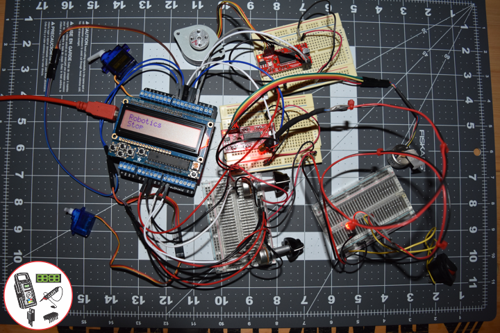
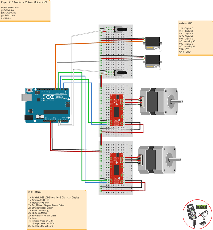
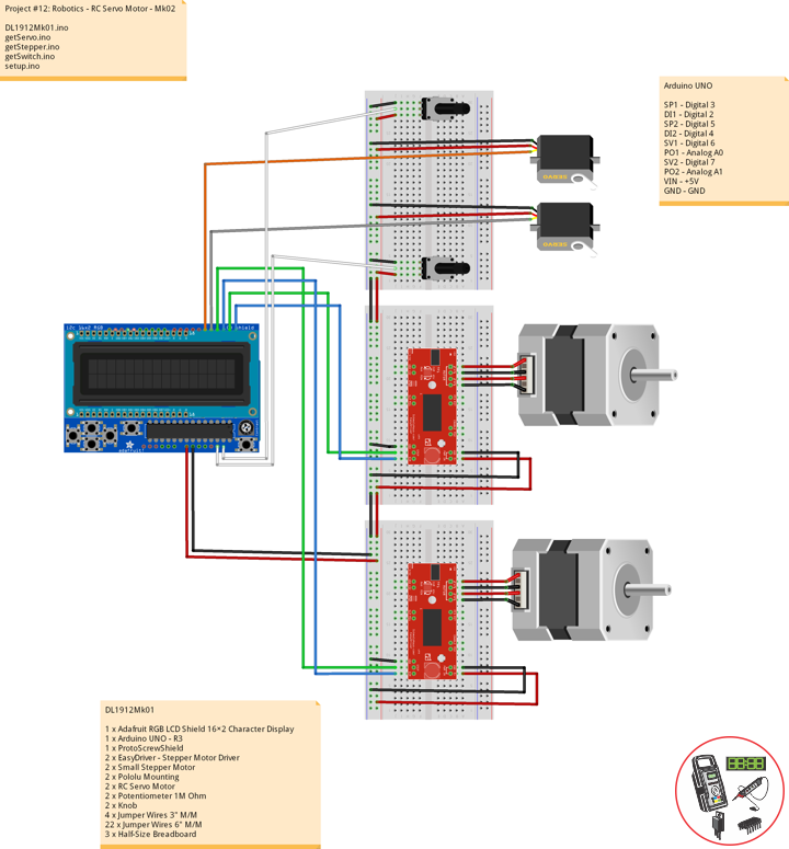
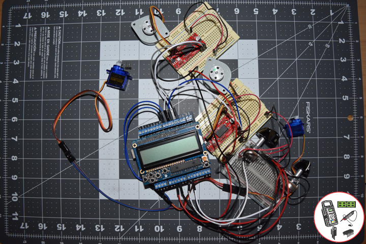
Project #12: Robotics – RC Servo Motor – Mk02
——
——
——
——
——
——
——
——
——
Servo (Radio Control)
Servos (also RC servos) are small, cheap, mass-produced servomotors or other actuators used for radio control and small-scale robotics.
Radio control servos are connected through a standard three-wire connection: two wires for a DC power supply and one for control, carrying a pulse-width modulation (PWM) signal. Each servo has a separate connection and PWM signal from the radio control receiver. This signal is easily generated by simple electronics, or by microcontrollers such as the Arduino. This, together with their low-cost, has led to their wide adoption for robotics and physical computing.
DL1912Mk01
1 x Adafruit RGB LCD Shield 16×2 Character Display
1 x Arduino UNO – R3
1 x ProtoScrewShield
2 x EasyDriver – Stepper Motor Driver
2 x Small Stepper Motor
2 x Pololu Mounting
2 x RC Servo Motor
2 x Potentiometer 1M Ohm
2 x Knob
4 x Jumper Wires 3″ M/M
22 x Jumper Wires 6″ M/M
3 x Half-Size Breadboard
Arduino UNO
SP1 – Digital 3
DI1 – Digital 2
SP2 – Digital 5
DI2 – Digital 4
SV1 – Digital 6
PO1 – Analog A0
SV2 – Digital 7
PO2 – Analog A1
VIN – +5V
GND – GND
DL1912Mk01.ino
// ***** Don Luc Electronics © *****
// Software Version Information
// Project #12: Robotics - RC Servo Motor - Mk02
// 12-01
// DL1912Mk01p.ino 12-02
// Arduino UNO
// Screw Shield
// Adafruit RGB LCD Shield
// 2 x Small Stepper Motor
// 2 x EasyDriver
// 2 x RC Servo Motor
// 2 x Potentiometer

// include the library code:
#include <Adafruit_RGBLCDShield.h>
#include <Servo.h>

// Adafruit RGB LCD Shield
Adafruit_RGBLCDShield RGBLCDShield = Adafruit_RGBLCDShield();

// These #defines make it easy to set the backlight color
#define OFF 0x0
#define RED 0x1
#define YELLOW 0x3
#define GREEN 0x2
#define TEAL 0x6
#define BLUE 0x4
#define VIOLET 0x5
#define WHITE 0x7

// Momentary Button
int yy = 0;
uint8_t momentaryButton = 0;

// 2 x EasyDriver
int dirPinR = 2;                           // EasyDriver Right
int stepPinR = 3;                          // stepPin Right
int dirPinL = 4;                           // EasyDriver Left
int stepPinL = 5;                          // stepPin Left
int i = 0;

// 2 x RC Servo Motor
// 2 x Potentiometer
Servo isRCServo1;                          // Create servo object to control a RCServo1
int servo1 = 6;                            // Servo 1
int iPot1 = A0;                            // Analog Potentiometer 1
int iVal1;                                 // Variable - Analog Potentiometer 1
Servo isRCServo2;                          // Create servo object to control a RCServo2
int servo2 = 7;                            // Servo 2
int iPot2 = A1;                            // Analog Potentiometer 2
int iVal2;                                 // Variable - Analog Potentiometer 2

void loop() {

  // Clear
  RGBLCDShield.clear();

  // Momentary Button
  momentaryButton = RGBLCDShield.readButtons();

  switch ( yy ) {
    case 1:

      // Up
      isSwitch1();

      break;
    case 2:

      // Down
      isSwitch2();

      break;
    case 3:

      // Right
      isSwitch3();

      break;
    case 4:

      // Left
      isSwitch4();

      break;
    case 5:

      // Stop
      isSwitch5();

      break;
    default:

      // Stop
      yy = 5;
      RGBLCDShield.setBacklight(RED);
      isSwitch5();

   }

   if ( momentaryButton ) {

    if ( momentaryButton & BUTTON_UP ) {

      yy = 1;
      // Up
      RGBLCDShield.setBacklight(GREEN);

    }

    if ( momentaryButton & BUTTON_DOWN ) {

      yy = 2;
      // Down
      RGBLCDShield.setBacklight(VIOLET);

    }

    if ( momentaryButton & BUTTON_LEFT ) {

      yy = 3;
      // Right
      RGBLCDShield.setBacklight(TEAL);

    }

    if ( momentaryButton & BUTTON_RIGHT ) {

      yy = 4;
      // Left
      RGBLCDShield.setBacklight(YELLOW);
    }

    if ( momentaryButton & BUTTON_SELECT ) {

      yy = 5;
      // Stop
      RGBLCDShield.setBacklight(RED);

    }

  }

}
getServo.ino
// Servo
// isServoSetup
void isServoSetup() {
// 2 x RC Servo Motor
isRCServo1.attach( servo1 );
isRCServo2.attach( servo2 );
}
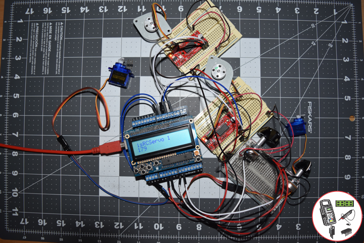
// isServo1
void isServo1() {
// EasyDriver
isStepperStop();
// Potentiometer RC Servo Motor 1
iVal1 = analogRead( iPot1 ); // Reads the value of the iPot1 (Value between 0 and 1023)
iVal1 = map(iVal1, 0, 1023, 0, 180); // Scale it to use it with the isRCServo1 (Value between 0 and 180)
isRCServo1.write( iVal1 ); // isRCServo1 sets the servo position according to the scaled value
delay(15);
// Display
// Set the cursor to column 0, line 0
RGBLCDShield.setCursor(0,0);
RGBLCDShield.print("isRCServo 1"); // isRCServo 1
// Set the cursor to column 0, line 1
RGBLCDShield.setCursor(0, 1);
RGBLCDShield.print( iVal1 ); // Reads the value iVal1
delay(500);
}
// isServo2
void isServo2() {
// EasyDriver
isStepperStop();
// Potentiometer RC Servo Motor 1
iVal2 = analogRead( iPot2 ); // Reads the value of the iPot2 (Value between 0 and 1023)
iVal2 = map(iVal2, 0, 1023, 0, 180); // Scale it to use it with the isRCServo2 (Value between 0 and 180)
isRCServo2.write( iVal2 ); // isRCServo2 sets the servo position according to the scaled value
delay(15);
// Display
// Set the cursor to column 0, line 0
RGBLCDShield.setCursor(0,0);
RGBLCDShield.print("isRCServo 2"); // isRCServo 2
// Set the cursor to column 0, line 1
RGBLCDShield.setCursor(0, 1);
RGBLCDShield.print( iVal2 ); // Reads the value iVal2
delay(500);
}
getStepper.ino
// Stepper
// isStepperSetup
void isStepperSetup() {
// 2 x EasyDriver
pinMode(dirPinR, OUTPUT);
pinMode(stepPinR, OUTPUT);
pinMode(dirPinL, OUTPUT);
pinMode(stepPinL, OUTPUT);
}
// isStepper1
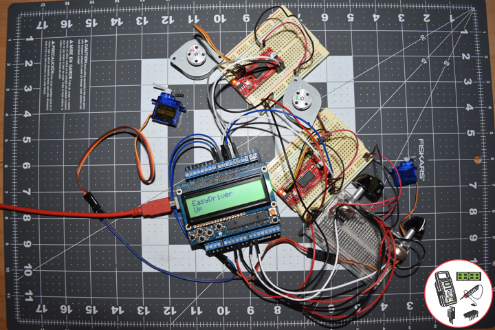
void isStepper1(){
// set the cursor to column 0, line 0
RGBLCDShield.setCursor(0,0);
RGBLCDShield.print("EasyDriver"); // EasyDriver
RGBLCDShield.setCursor(0,1);
RGBLCDShield.print("Up");
delay(500);
// 2 x EasyDriver
digitalWrite(dirPinR, LOW); // Set the direction.
delay(100);
digitalWrite(dirPinL, LOW); // Set the direction.
delay(100);
for (i = 0; i<300; i++) // Iterate for 1000 microsteps.
{
digitalWrite(stepPinR, LOW); // This LOW to HIGH change is what creates the
digitalWrite(stepPinR, HIGH); // "Rising Edge" so the easydriver knows to when to step.
delayMicroseconds(170); // This delay time is close to top speed.
digitalWrite(stepPinL, LOW); // This LOW to HIGH change is what creates the
digitalWrite(stepPinL, HIGH); // "Rising Edge" so the easydriver knows to when to step.
delayMicroseconds(170); // This delay time is close to top speed.
}
}
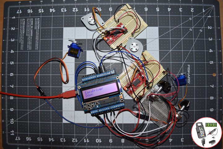
// isStepper2
void isStepper2(){
// set the cursor to column 0, line 0
RGBLCDShield.setCursor(0,0);
RGBLCDShield.print("EasyDriver"); // EasyDriver
RGBLCDShield.setCursor(0,1);
RGBLCDShield.print("Down");
delay(500);
// 2 x EasyDriver
digitalWrite(dirPinR, HIGH); // Set the direction.
delay(100);
digitalWrite(dirPinL, HIGH); // Set the direction.
delay(100);
for (i = 0; i<300; i++) // Iterate for 1000 microsteps.
{
digitalWrite(stepPinR, LOW); // This LOW to HIGH change is what creates the
digitalWrite(stepPinR, HIGH); // "Rising Edge" so the easydriver knows to when to step.
delayMicroseconds(170); // This delay time is close to top speed.
digitalWrite(stepPinL, LOW); // This LOW to HIGH change is what creates the
digitalWrite(stepPinL, HIGH); // "Rising Edge" so the easydriver knows to when to step.
delayMicroseconds(170); // This delay time is close to top speed.
}
}
// isStepperStop
void isStepperStop() {
// 2 x EasyDriver
digitalWrite(dirPinR, LOW); // Set the direction.
delay(100);
digitalWrite(dirPinL, LOW); // Set the direction.
delay(100);
digitalWrite(stepPinR, LOW); // This LOW to HIGH change is what creates the
digitalWrite(stepPinL, LOW); // This LOW to HIGH change is what creates the
}
getSwitch.ino
// Switch
// Switch 1
void isSwitch1(){

   // Up
   yy = 1;

   // 2 x EasyDriver
   isStepper1();

}
// Switch 2
void isSwitch2(){

   // Down
   yy = 2;

   // 2 x EasyDriver
   isStepper2();

}
// Switch 3
void isSwitch3(){

   // Right
   yy = 3;

   // Potentiometer RC Servo Motor 1
   isServo1();

}
// Switch 4
void isSwitch4(){

   // Left
   yy = 4;

   // Potentiometer RC Servo Motor 2
   isServo2();

}
// Switch 5
void isSwitch5(){

   // Stop
   yy = 5;

   // set the cursor to column 0, line 0
   RGBLCDShield.setCursor(0,0);
   RGBLCDShield.print("Robotics");         // Robotics
   RGBLCDShield.setCursor(0,1);
   RGBLCDShield.print("Stop");

   delay( 500 );

   // EasyDriver
   isStepperStop();

}
setup.ino
// Setup
void setup() {

  // Adafruit RGB LCD Shield
  // Set up the LCD's number of columns and rows:
  RGBLCDShield.begin(16, 2);
  RGBLCDShield.setBacklight(GREEN);

  // Display
  // Set the cursor to column 0, line 0
  RGBLCDShield.setCursor(0,0);
  RGBLCDShield.print("Don Luc Electron");         // Don luc Electron
  // Set the cursor to column 0, line 1
  RGBLCDShield.setCursor(0, 1);
  RGBLCDShield.print("Robotics");                // EasyDriver

  delay(5000);

  // Clear
  RGBLCDShield.clear();

  // 2 x EasyDriver
  isStepperSetup();

  // 2 x RC Servo Motor
  isServoSetup();

}
Follow Us
Web: https://www.donluc.com/
Web: http://neosteamlabs.com/
Web: http://www.jlpconsultants.com/
YouTube: https://www.youtube.com/channel/UC5eRjrGn1CqkkGfZy0jxEdA
Facebook: https://www.facebook.com/neosteam.labs.9/
Instagram: https://www.instagram.com/neosteamlabs/
Pinterest: https://www.pinterest.com/NeoSteamLabs/
Twitter: https://twitter.com/labs_steam
Etsy: https://www.etsy.com/shop/NeoSteamLabs
Don Luc
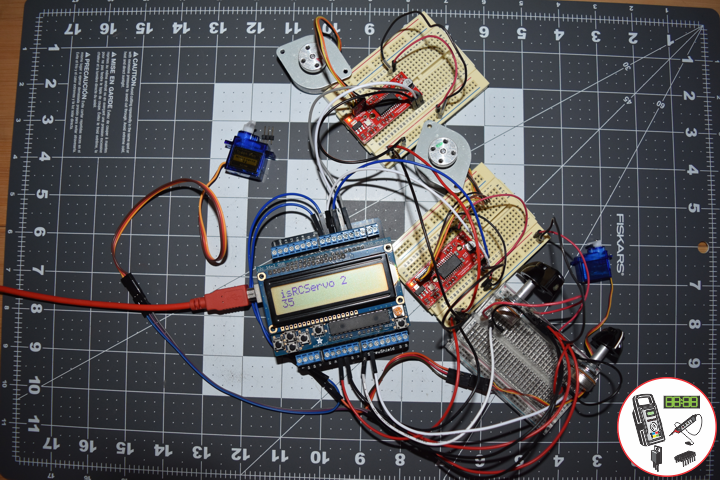
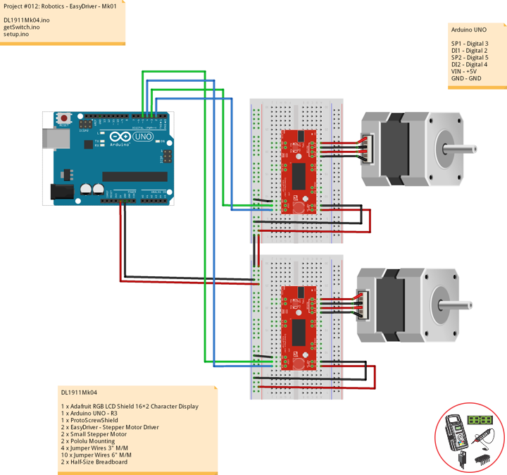
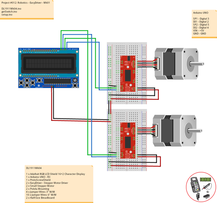
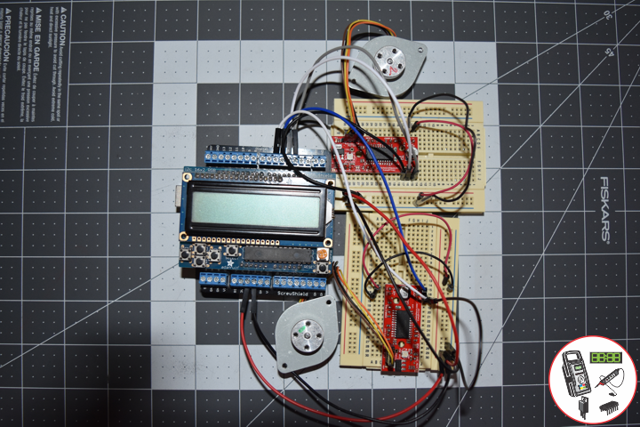
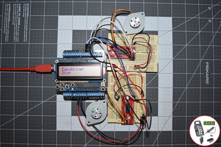
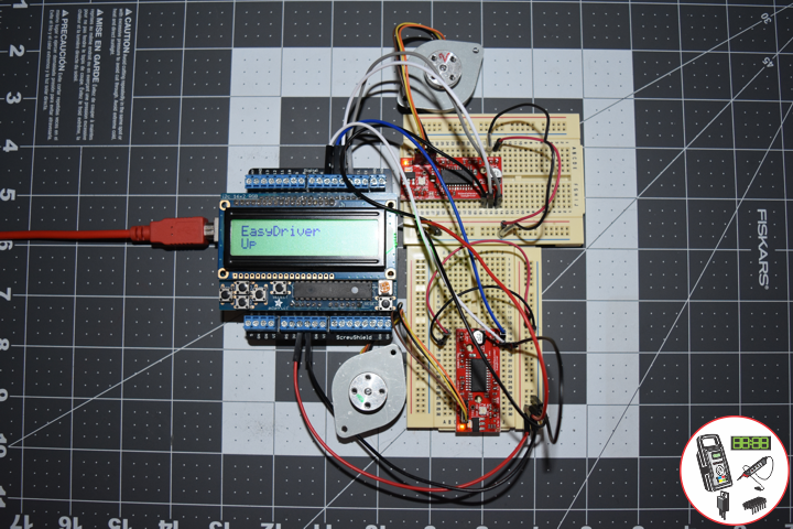
Project #12: Robotics – EasyDriver – Mk01
——
——
——
——
——
——
Small Stepper Motor
Stepper motors are great motors for position control. They can be found in desktop printers, plotters, 3D printers, CNC milling machines, and anything else requiring precise position control. Steppers are a special segment of brushless motors. They are purposely built for high-holding torque. This high-holding torque gives the user the ability to incrementally “step” to the next position. This results in a simple positioning system that doesn’t require an encoder. This makes stepper motor controllers very simple to build and use. These small steppers are a great way to get things moving, especially when positioning and repeatability is a concern. This is a Bipolar motor.
Pros
Excellent position accuracy
High holding torque
High reliability
Most steppers come in standard sizes
Cons
Small step distance limits top speed
It’s possible to “skip” steps with high loads
Draws maximum current constantly
DL1911Mk04
1 x Adafruit RGB LCD Shield 16×2 Character Display
1 x Arduino UNO – R3
1 x ProtoScrewShield
2 x EasyDriver – Stepper Motor Driver
2 x Small Stepper Motor
2 x Pololu Mounting
4 x Jumper Wires 3″ M/M
10 x Jumper Wires 6″ M/M
2 x Half-Size Breadboard
Arduino UNO
SP1 – Digital 3
DI1 – Digital 2
SP2 – Digital 5
DI2 – Digital 4
VIN – +5V
GND – GND
DL1911Mk04.ino
// ***** Don Luc Electronics © *****
// Software Version Information
// Project #12: Robotics - EasyDriver - Mk01
// 11-04
// DL1911Mk04p.ino 12-01
// Arduino UNO
// Screw Shield
// Adafruit RGB LCD Shield
// 2 x Small Stepper Motor
// 2 x EasyDriver

// include the library code:
#include <Adafruit_RGBLCDShield.h>

// Adafruit RGB LCD Shield
Adafruit_RGBLCDShield RGBLCDShield = Adafruit_RGBLCDShield();

// These #defines make it easy to set the backlight color
#define OFF 0x0
#define RED 0x1
#define YELLOW 0x3
#define GREEN 0x2
#define TEAL 0x6
#define BLUE 0x4
#define VIOLET 0x5
#define WHITE 0x7

// Momentary Button
int yy = 0;
uint8_t momentaryButton = 0;

// 2 x EasyDriver
int dirPinR = 2;                           // EasyDriver Right
int stepPinR = 3;                          // stepPin Right
int dirPinL = 4;                           // EasyDriver Left
int stepPinL = 5;                          // stepPin Left
int i = 0;

void loop() {

  // Clear
  RGBLCDShield.clear();

  // Momentary Button
  momentaryButton = RGBLCDShield.readButtons();

  switch ( yy ) {
    case 1:

      // Up
      isSwitch1();

      break;
    case 2:

      // Down
      isSwitch2();

      break;
    case 3:

      // Right
      isSwitch3();

      break;
    case 4:

      // Left
      isSwitch4();

      break;
    case 5:

      // Stop
      isSwitch5();

      break;
    default:

      // Stop
      yy = 5;
      RGBLCDShield.setBacklight(RED);
      isSwitch5();

   }

   if ( momentaryButton ) {

    if ( momentaryButton & BUTTON_UP ) {

      yy = 1;
      // Up
      RGBLCDShield.setBacklight(GREEN);

    }

    if ( momentaryButton & BUTTON_DOWN ) {

      yy = 2;
      // Down
      RGBLCDShield.setBacklight(VIOLET);

    }

    if ( momentaryButton & BUTTON_LEFT ) {

      yy = 3;
      // Right
      RGBLCDShield.setBacklight(TEAL);

    }

    if ( momentaryButton & BUTTON_RIGHT ) {

      yy = 4;
      // Left
      RGBLCDShield.setBacklight(YELLOW);
    }

    if ( momentaryButton & BUTTON_SELECT ) {

      yy = 5;
      // Stop
      RGBLCDShield.setBacklight(RED);

    }

  }

}
getSwitch.ino
// Switch
// Switch 1
void isSwitch1(){

   // Up
   yy = 1;

   // set the cursor to column 0, line 0
   RGBLCDShield.setCursor(0,0);
   RGBLCDShield.print("EasyDriver");        // EasyDriver
   RGBLCDShield.setCursor(0,1);
   RGBLCDShield.print("Up");

   // 2 x EasyDriver
   digitalWrite(dirPinR, LOW);              // Set the direction.
   delay(100);
   digitalWrite(dirPinL, LOW);              // Set the direction.
   delay(100);

   for (i = 0; i<1000; i++)                 // Iterate for 1000 microsteps.
   {
     digitalWrite(stepPinR, LOW);           // This LOW to HIGH change is what creates the
     digitalWrite(stepPinR, HIGH);          // "Rising Edge" so the easydriver knows to when to step.
     delayMicroseconds(170);                // This delay time is close to top speed.
     digitalWrite(stepPinL, LOW);           // This LOW to HIGH change is what creates the
     digitalWrite(stepPinL, HIGH);          // "Rising Edge" so the easydriver knows to when to step.
     delayMicroseconds(170);                // This delay time is close to top speed.
   }

}
// Switch 2
void isSwitch2(){

   // Down
   yy = 2;

   // set the cursor to column 0, line 0
   RGBLCDShield.setCursor(0,0);
   RGBLCDShield.print("EasyDriver");         // EasyDriver
   RGBLCDShield.setCursor(0,1);
   RGBLCDShield.print("Down");

   // 2 x EasyDriver
   digitalWrite(dirPinR, HIGH);              // Set the direction.
   delay(100);
   digitalWrite(dirPinL, HIGH);              // Set the direction.
   delay(100);

   for (i = 0; i<1000; i++)                 // Iterate for 1000 microsteps.
   {
     digitalWrite(stepPinR, LOW);           // This LOW to HIGH change is what creates the
     digitalWrite(stepPinR, HIGH);          // "Rising Edge" so the easydriver knows to when to step.
     delayMicroseconds(170);                // This delay time is close to top speed.
     digitalWrite(stepPinL, LOW);           // This LOW to HIGH change is what creates the
     digitalWrite(stepPinL, HIGH);          // "Rising Edge" so the easydriver knows to when to step.
     delayMicroseconds(170);                // This delay time is close to top speed.
   }

}
// Switch 3
void isSwitch3(){

   // Right
   yy = 3;

   // set the cursor to column 0, line 0
   RGBLCDShield.setCursor(0,0);
   RGBLCDShield.print("EasyDriver");        // EasyDriver
   RGBLCDShield.setCursor(0,1);
   RGBLCDShield.print("Hight");

   // 2 x EasyDriver
   digitalWrite(dirPinR, LOW);               // Set the direction.
   delay(100);
   digitalWrite(dirPinL, HIGH);              // Set the direction.
   delay(100);

   for (i = 0; i<1000; i++)                 // Iterate for 1000 microsteps.
   {
     digitalWrite(stepPinR, LOW);           // This LOW to HIGH change is what creates the
     digitalWrite(stepPinR, HIGH);          // "Rising Edge" so the easydriver knows to when to step.
     delayMicroseconds(170);                // This delay time is close to top speed.
     digitalWrite(stepPinL, LOW);           // This LOW to HIGH change is what creates the
     digitalWrite(stepPinL, HIGH);          // "Rising Edge" so the easydriver knows to when to step.
     delayMicroseconds(170);                // This delay time is close to top speed.
   }

}
// Switch 4
void isSwitch4(){

   // Left
   yy = 4;

   // set the cursor to column 0, line 0
   RGBLCDShield.setCursor(0,0);
   RGBLCDShield.print("EasyDriver");        // EasyDriver
   RGBLCDShield.setCursor(0,1);
   RGBLCDShield.print("Left");

   // 2 x EasyDriver
   digitalWrite(dirPinR, HIGH);             // Set the direction.
   delay(100);
   digitalWrite(dirPinL, LOW);              // Set the direction.
   delay(100);

   for (i = 0; i<1000; i++)                 // Iterate for 1000 microsteps.
   {
     digitalWrite(stepPinR, LOW);           // This LOW to HIGH change is what creates the
     digitalWrite(stepPinR, HIGH);          // "Rising Edge" so the easydriver knows to when to step.
     delayMicroseconds(170);                // This delay time is close to top speed.
     digitalWrite(stepPinL, LOW);           // This LOW to HIGH change is what creates the
     digitalWrite(stepPinL, HIGH);          // "Rising Edge" so the easydriver knows to when to step.
     delayMicroseconds(170);                // This delay time is close to top speed.
   }

}
// Switch 5
void isSwitch5(){

   // Stop
   yy = 5;

   // set the cursor to column 0, line 0
   RGBLCDShield.setCursor(0,0);
   RGBLCDShield.print("EasyDriver");        // EasyDriver
   RGBLCDShield.setCursor(0,1);
   RGBLCDShield.print("Stop");

   delay( 1000 );

   // 2 x EasyDriver
   digitalWrite(dirPinR, LOW);              // Set the direction.
   delay(100);
   digitalWrite(dirPinL, LOW);              // Set the direction.
   delay(100);
   digitalWrite(stepPinR, LOW);             // This LOW to HIGH change is what creates the
   digitalWrite(stepPinL, LOW);             // This LOW to HIGH change is what creates the

}
setup.ino
// Setup
void setup() {

  // Adafruit RGB LCD Shield
  // Set up the LCD's number of columns and rows:
  RGBLCDShield.begin(16, 2);
  RGBLCDShield.setBacklight(GREEN);

  // Display
  // Set the cursor to column 0, line 0
  RGBLCDShield.setCursor(0,0);
  RGBLCDShield.print("Don Luc Electron");         // Don luc Electron
  // Set the cursor to column 0, line 1
  RGBLCDShield.setCursor(0, 1);
  RGBLCDShield.print("EasyDriver");               // EasyDriver

  delay(5000);

  // Clear
  RGBLCDShield.clear();

  // 2 x EasyDriver
  pinMode(dirPinR, OUTPUT);
  pinMode(stepPinR, OUTPUT);
  pinMode(dirPinL, OUTPUT);
  pinMode(stepPinL, OUTPUT);

}
Follow Us
Web: https://www.donluc.com/
Web: http://neosteamlabs.com/
Web: http://www.jlpconsultants.com/
YouTube: https://www.youtube.com/channel/UC5eRjrGn1CqkkGfZy0jxEdA
Facebook: https://www.facebook.com/neosteam.labs.9/
Instagram: https://www.instagram.com/neosteamlabs/
Pinterest: https://www.pinterest.com/NeoSteamLabs/
Twitter: https://twitter.com/labs_steam
Etsy: https://www.etsy.com/shop/NeoSteamLabs
Don Luc
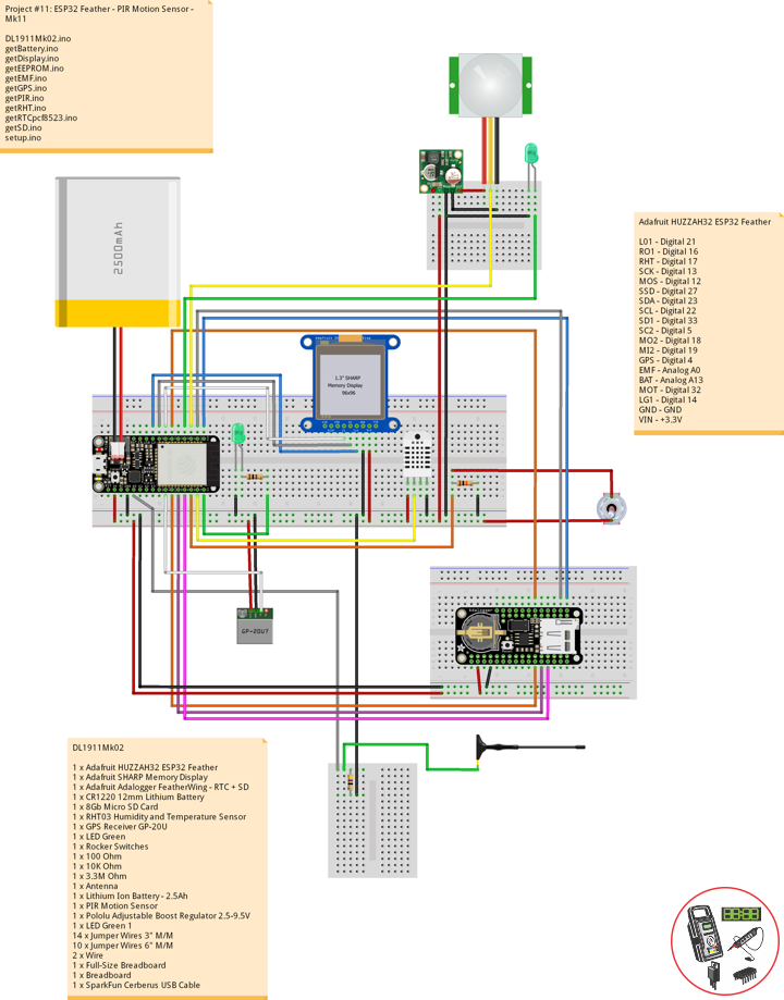
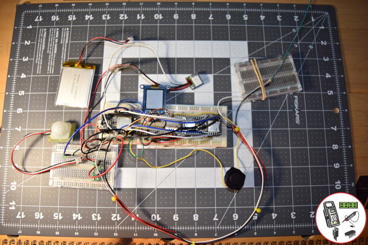
Project #11: ESP32 Feather – PIR Motion Sensor – Mk11
PIR Motion Sensor
——
——
——
——
——
——
PIR Motion Sensor
Passive infrared (PIR) sensors are motion-detecting devices used in security systems across the world, even though you may not see them, they probably see you.
This is a simple to use motion sensor. Power it up and wait 1-2 seconds for the sensor to get a snapshot of the still room. If anything moves after that period, the ‘alarm’ pin will go low.
Pololu Adjustable Boost Regulator 2.5-9.5V
This powerful, adjustable boost regulator can generate an output voltage as high as 9.5 V from an input voltage as low as 1.5 V, all in a compact, 0.42″ x 0.88″ x 0.23″ package. A trimmer potentiometer lets you set the boost regulator’s output voltage to a value between 2.5 and 9.5 V.
DL1911Mk02
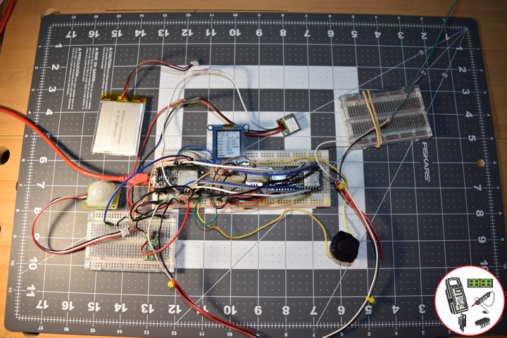
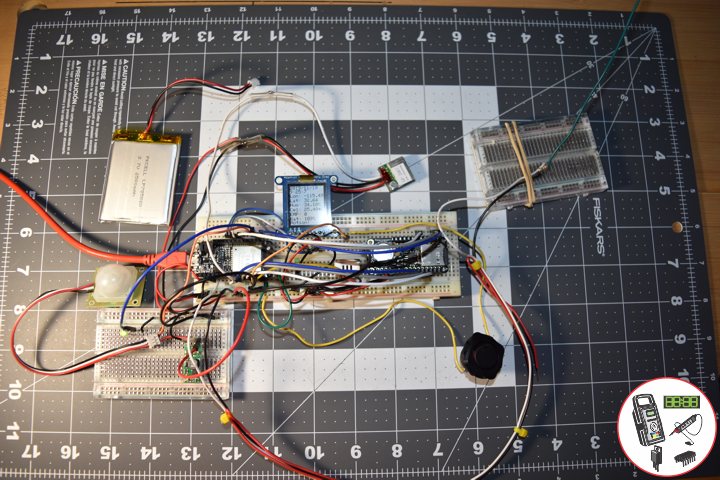
1 x Adafruit HUZZAH32 ESP32 Feather
1 x Adafruit SHARP Memory Display
1 x Adafruit Adalogger FeatherWing – RTC + SD
1 x CR1220 12mm Lithium Battery
1 x 8Gb Micro SD Card
1 x RHT03 Humidity and Temperature Sensor
1 x GPS Receiver GP-20U
1 x LED Green
1 x Rocker Switches
1 x 100 Ohm
1 x 10K Ohm
1 x 3.3M Ohm
1 x Antenna
1 x Lithium Ion Battery – 2.5Ah
1 x PIR Motion Sensor
1 x Pololu Adjustable Boost Regulator 2.5-9.5V
1 x LED Green 1
14 x Jumper Wires 3″ M/M
10 x Jumper Wires 6″ M/M
2 x Wire
1 x Full-Size Breadboard
2 x Breadboard
1 x SparkFun Cerberus USB Cable
Adafruit HUZZAH32 ESP32 Feather
LG0 – Digital 21
RO1 – Digital 16
RHT – Digital 17
SCK – Digital 13
MOS – Digital 12
SSD – Digital 27
SDA – Digital 23
SCL – Digital 22
SD1 – Digital 33
SC2 – Digital 5
MO2 – Digital 18
MI2 – Digital 19
GPS – Digital 4
EMF – Analog A0
BAT – Analog A13
MOT – Digital 32
LG1 – Digital 14
GND – GND
VIN – +3.3V
DL1911Mk02.ino
// ***** Don Luc Electronics *****
// Software Version Information
// Project #11: HUZZAH32 ESP32 Feather - PIR Motion - Mk11
// 11-02
// DL1911Mk02p.ino 11-11
// Adafruit HUZZAH32 ESP32 Feather Board
// SHARP Display
// LED Green
// Adalogger FeatherWing - RTC + SD
// EEPROM
// RHT03 Humidity and Temperature Sensor
// Rocker Switches
// GPS Receiver
// EMF Meter (Single Axis)
// Lithium Ion Battery - 2.5Ah
// PIR Motion
// Pololu Adjustable Boost Regulator 2.5-9.5V
// LED Green 1

// include Library Code
// SHARP Memory Display
#include <Adafruit_SharpMem.h>
#include <Adafruit_GFX.h>
// Date and Time
#include "RTClib.h"
// EEPROM library to read EEPROM with unique ID for unit
#include "EEPROM.h"
// RHT Humidity and Temperature Sensor
#include <SparkFun_RHT03.h>
// SD Card
#include "FS.h"
#include "SD.h"
#include "SPI.h"
// GPS Receiver
#include <TinyGPS++.h>
#include <HardwareSerial.h>

// SHARP Memory Display
// any pins can be used
#define SHARP_SCK  13
#define SHARP_MOSI 12
#define SHARP_SS   27
// Set the size of the display here, e.g. 144x168!
Adafruit_SharpMem display(SHARP_SCK, SHARP_MOSI, SHARP_SS, 144, 168);
// The currently-available SHARP Memory Display (144x168 pixels)
// requires > 4K of microcontroller RAM; it WILL NOT WORK on Arduino Uno
// or other <4K "classic" devices!
#define BLACK 0
#define WHITE 1
int minorHalfSize; // 1/2 of lesser of display width or height

// LED Green
int iLEDGreen =  21;                 // LED Green

// PCF8523 Precision RTC
RTC_PCF8523 rtc;
String dateRTC = "";
String timeRTC = "";

// RHT Humidity and Temperature Sensor
const int RHT03_DATA_PIN = 17;          // RHT03 data pin Digital 17
RHT03 rht;                              // This creates a RTH03 object, which we'll use to interact with the sensor
float latestHumidity;
float latestTempC;
float latestTempF;

// SD Card
const int chipSelect = 33;              // SD Card
String zzzzzz = "";

// Rocker Switches
int iRow1 = 16;                         // Rocker Switches Digital 16
int iRow1State = 0;                     // Variable for reading the pushbutton status

// ESP32 HardwareSerial
HardwareSerial tGPS(2);

// GPS Receiver
#define gpsRXPIN 4
#define gpsTXPIN 36                     // This one is unused and doesnt have a conection
// The TinyGPS++ object
TinyGPSPlus gps;
float TargetLat;
float TargetLon;
int Status = 0;

// EMF Meter (Single Axis)
#define NUMREADINGS 15                    // Raise this number to increase data smoothing
int senseLimit = 15;                      // Raise this number to decrease sensitivity (up to 1023 max)
int val = 0;                              // Val
int iEMF = A0;                            // EMF Meter
int readings[ NUMREADINGS ];              // Readings from the analog input
int ind = 0;                              // Index of the current reading
int total = 0;                            // Running total
int average = 0;                          // Final average of the probe reading
int iEMFDis = 0;
int iEMFRect = 0;

// LiPo Battery
const int bat = A13;                      // LiPo Battery
uint16_t vbat = 0;
int iBat = 0;

// PIR Motion
const int iMotion = 32;                   // Motion detector
const int iLEDGreen1 = 14;                // LED Green 1
int proximity = LOW;                      // Proximity
String Det = "";

// The current address in the EEPROM (i.e. which byte
// we're going to  read to next)
#define EEPROM_SIZE 64
String sver = "11-2.p";
// Unit ID information
String uid = "";

void loop() {

  // Receives NEMA data from GPS receiver
  // This sketch displays information every time a new sentence is correctly encoded.
  while ( tGPS.available() > 0)
    if (gps.encode( tGPS.read() ))
    {
     displayInfo();
    }

  if (millis() > 5000 && gps.charsProcessed() < 10)
  {
    while(true);
  }

  // Date and Time
  isRTC();

  // RHT03 Humidity and Temperature Sensor
  isRHT03();

  // SHARP Memory Display On
  isDisplayOn();

  // Rocker Switched
  // Read the state of the iRow1 value
  iRow1State = digitalRead(iRow1);

  // EMF Meter (Single Axis)
  isEMF();

  // LiPo Battery
  isBattery();

  // isPIR Motion
  isPIR();

  // Check if the pushbutton is pressed. If it is, the buttonState is HIGH:
  if (iRow1State == HIGH) {

    // iLEDGreen
    digitalWrite(iLEDGreen,  HIGH );
    // SD Card
    isSD();

  } else {

    // iLEDGreen
    digitalWrite(iLEDGreen,  LOW );

  }

  // Delay
  delay( 1000 );

}
getBattery.ino
// LiPo Battery
void isBattery() {

  // Battery
  vbat = analogRead(bat);
  vbat = vbat / 2;

  iBat = map( vbat, 1, 1064, 1, 100);

}
getDisplay.ino
// SHARP Memory Display On
void isDisplayOn() {

    // Clear Display
    display.clearDisplay();
    // Text display date, time, LED on, Etc...
    display.setRotation(4);
    display.setTextSize(2);
    display.setTextColor(BLACK);
    // Date
    display.setCursor(0,1);
    display.println( dateRTC );
    // Time
    display.setCursor(0,17);
    display.println( timeRTC );
    // Longitude
    display.setCursor(0,35);
    display.print("Lon: ");
    display.println( TargetLon );
    // Latitude
    display.setCursor(0,55);
    display.print("Lat: ");
    display.println( TargetLat );
    // Humidity
    display.setCursor(0,74);
    display.print("Hum: ");
    display.print( latestHumidity );
    display.println("%");
    // Temp C
    display.setCursor(0,94);
    display.print("Cel: ");
    display.print( latestTempC );
    display.println("*C");
    // EMF Meter
    display.setCursor(0,114);
    display.print("EMF: ");
    display.println( iEMFDis );
    // Battery
    display.setCursor(0,134);
    display.print("Bat: ");
    display.print( iBat );
    display.println( "%" );
    // PIR Motion
    display.println( Det );
    display.setCursor(0,154);
    // Refresh
    display.refresh();

}
// SHARP Memory Display - UID
void isDisplayUID() {

    // Clear Display
    display.clearDisplay();
    // text display EEPROM
    display.setRotation(4);
    display.setTextSize(2);
    display.setTextColor(BLACK);
    // EEPROM with Unique ID
    display.setCursor(0,20);
    display.print( "UID: " );
    display.println( uid );
    // Version
    display.setCursor(0,45);
    display.print( "VER: ");
    display.println( sver  );
    // Refresh
    display.refresh();
    delay( 100 );

}
getEEPROM.ino
// EEPROM
void GetUID()
{

  // Get unit ID
  uid = "";
  for (int x = 0; x < 5; x++)
  {
    uid = uid + char(EEPROM.read(x));
  }

}
getEMF.ino
// EMF Meter (Single Axis)
// setupEMF
void setupEMF() {

  // EMF Meter (Single Axis)
  pinMode( iEMF, OUTPUT ); // EMF Meter
  for (int i = 0; i < NUMREADINGS; i++){
    readings[ i ] = 0;     // Initialize all the readings to 0
  }

}
// isEMF
void isEMF(){

  // Probe
  val = analogRead( iEMF );                    // Take a reading from the probe

  if( val >= 1 ){                              // If the reading isn't zero, proceed

    val = constrain( val, 1, senseLimit );     // Turn any reading higher than the senseLimit value into the senseLimit value
    val = map( val, 1, senseLimit, 1, 1023 );  // Remap the constrained value within a 1 to 1023 range

    total -= readings[ ind ];                  // Subtract the last reading
    readings[ ind ] = val;                     // Read from the sensor
    total += readings[ ind ];                  // Add the reading to the total
    ind = ( ind + 1 );                         // Advance to the next index

    if ( ind >= NUMREADINGS ) {                // If we're at the end of the array...
      ind = 0;                                 // ...wrap around to the beginning
    }

    average = total / NUMREADINGS;             // Calculate the average


   // average = val;
  }
  else
  {

    iEMFRect = 0;
    val = 0;
    average = 0;

  }

  iEMFDis = average;
  iEMFRect = map( average, 1, 1023, 1, 144 );

}
getGPS.ino
// GPS Receiver
void setupGPS() {

  // Setup GPS
  tGPS.begin(  9600 , SERIAL_8N1, gpsRXPIN, gpsTXPIN );

}
// GPS Vector Pointer Target
void displayInfo()
{

  // Location
  if (gps.location.isValid())
  {

    TargetLat = gps.location.lat();
    TargetLon = gps.location.lng();
    Status = 2;

  }
  else
  {

    Status = 0;

  }

}
getPIR.ino
// PIR Motion
void setupPIR() {

  // Setup PIR Montion
  pinMode(iMotion, INPUT_PULLUP);
  pinMode(iLEDGreen1, OUTPUT);

}
// isPIR Motion
void isPIR() {

  // Proximity
  proximity = digitalRead(iMotion);
  if (proximity == LOW)
  {

    // PIR Motion Sensor's LOW, Motion is detected
    // LED Green 1 - HIGH
    digitalWrite(iLEDGreen1, HIGH);
    Det = "Motion!";

  }
  else
  {

    // PIR Motion Sensor's HIGH
    // LED Green 1 - LOW
    digitalWrite(iLEDGreen1, LOW);
    Det = "****";

  }

}
getRHT.ino
// RHT03 Humidity and Temperature Sensor
void isRHT03(){

  // Call rht.update() to get new humidity and temperature values from the sensor.
  int updateRet = rht.update();

  // The humidity(), tempC(), and tempF() functions can be called -- after
  // a successful update() -- to get the last humidity and temperature value
  latestHumidity = rht.humidity();
  latestTempC = rht.tempC();
  latestTempF = rht.tempF();

}
getRTCpcf8523.ino
// PCF8523 Precision RTC
void setupRTC() {

  // pcf8523 Precision RTC
  if (! rtc.begin()) {
    while (1);
  }
  if (! rtc.initialized()) {
    // Following line sets the RTC to the date & time this sketch was compiled
    rtc.adjust(DateTime(F(__DATE__), F(__TIME__)));
    // This line sets the RTC with an explicit date & time, for example to set
    // January 21, 2014 at 3am you would call:
    // rtc.adjust(DateTime(2018, 9, 29, 12, 17, 0));
  }

}
// Date and Time RTC
void isRTC () {

  // Date and Time
  DateTime now = rtc.now();
  // Date
  dateRTC = now.year(), DEC;
  dateRTC = dateRTC + "/";
  dateRTC = dateRTC + now.month(), DEC;
  dateRTC = dateRTC + "/";
  dateRTC = dateRTC + now.day(), DEC;
  // Time
  timeRTC = now.hour(), DEC;
  timeRTC = timeRTC + ":";
  timeRTC = timeRTC + now.minute(), DEC;
  timeRTC = timeRTC + ":";
  timeRTC = timeRTC + now.second(), DEC;

}
getSD.ino
// SD Card
void setupSD() {

  // SD Card
    pinMode( chipSelect , OUTPUT );
    if(!SD.begin( chipSelect )){
        ;
        return;
    }
    uint8_t cardType = SD.cardType();

    if(cardType == CARD_NONE){
        ;
        return;
    }

    //Serial.print("SD Card Type: ");
    if(cardType == CARD_MMC){
        ;
    } else if(cardType == CARD_SD){
        ;
    } else if(cardType == CARD_SDHC){
        ;
    } else {
        ;
    }

    uint64_t cardSize = SD.cardSize() / (1024 * 1024);

}
// SD Card
void isSD() {

  zzzzzz = "";

  zzzzzz = uid + "|" + sver + "|" + dateRTC + "|" + timeRTC + "|" + Status + "|" + TargetLon + "|" + TargetLat + "|" + latestHumidity + "|" + latestTempC + "|" + latestTempF + "|" + average + "|" + iBat + "|" + Det + "|\r";

  char msg[zzzzzz.length() + 1];

  zzzzzz.toCharArray(msg, zzzzzz.length() + 1);

  appendFile(SD, "/espdata.txt", msg );

}
// List Dir
void listDir(fs::FS &fs, const char * dirname, uint8_t levels){
    dirname;
    File root = fs.open(dirname);
    if(!root){
        return;
    }
    if(!root.isDirectory()){
        return;
    }

    File file = root.openNextFile();
    while(file){
        if(file.isDirectory()){
            file.name();
            if(levels){
                listDir(fs, file.name(), levels -1);
            }
        } else {
            file.name();
            file.size();
        }
        file = root.openNextFile();
    }
}
// Write File
void writeFile(fs::FS &fs, const char * path, const char * message){
    path;
    File file = fs.open(path, FILE_WRITE);
    if(!file){
        return;
    }
    if(file.print(message)){
        ;
    } else {
        ;
    }
    file.close();
}
// Append File
void appendFile(fs::FS &fs, const char * path, const char * message){
    //Serial.printf("Appending to file: %s\n", path);
    path;
    File file = fs.open(path, FILE_APPEND);
    if(!file){
        return;
    }
    if(file.print(message)){
        ;
    } else {
        ;
    }
    file.close();
}
setup.ino
// Setup
void setup() {

  // EEPROM with Unique ID
  EEPROM.begin(EEPROM_SIZE);

  // Get Unit ID
  GetUID();

  // GPS Receiver
  // Setup GPS
  setupGPS();

  // SHARP Display start & clear the display
  display.begin();
  display.clearDisplay();

  isDisplayUID();

  delay( 5000 );

  // Initialize the LED Green
  pinMode(iLEDGreen, OUTPUT);

  // PCF8523 Precision RTC
  setupRTC();

  // Date and Time RTC
  isRTC();

  // RHT03 Humidity and Temperature Sensor
  // Call rht.begin() to initialize the sensor and our data pin
  rht.begin(RHT03_DATA_PIN);

  // SD Card
  setupSD();

  // Rocker Switches
  pinMode(iRow1, INPUT);

  // EMF Meter (Single Axis)
  setupEMF();

  // PIR Motion
  setupPIR();

}
Follow Us
Web: https://www.donluc.com/
Web: http://neosteamlabs.com/
Web: http://www.jlpconsultants.com/
YouTube: https://www.youtube.com/channel/UC5eRjrGn1CqkkGfZy0jxEdA
Facebook: https://www.facebook.com/neosteam.labs.9/
Instagram: https://www.instagram.com/neosteamlabs/
Pinterest: https://www.pinterest.com/NeoSteamLabs/
Twitter: https://twitter.com/labs_steam
Etsy: https://www.etsy.com/shop/NeoSteamLabs
Project #11: ESP32 Feather – LiPo 2.5Ah – Mk10
——
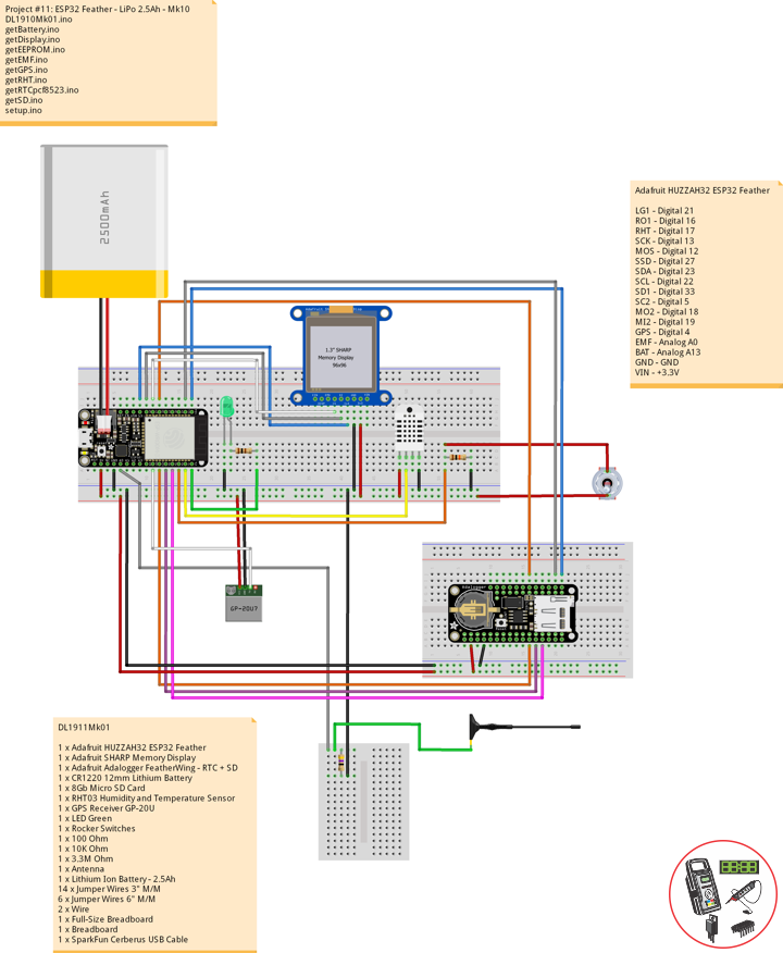
——
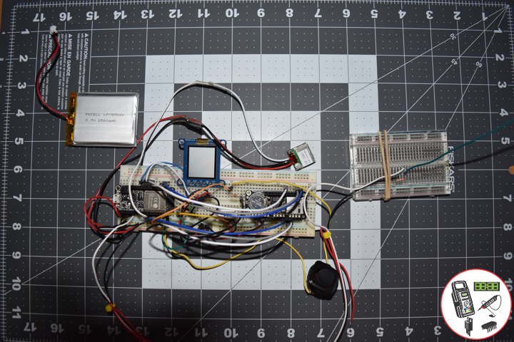
——
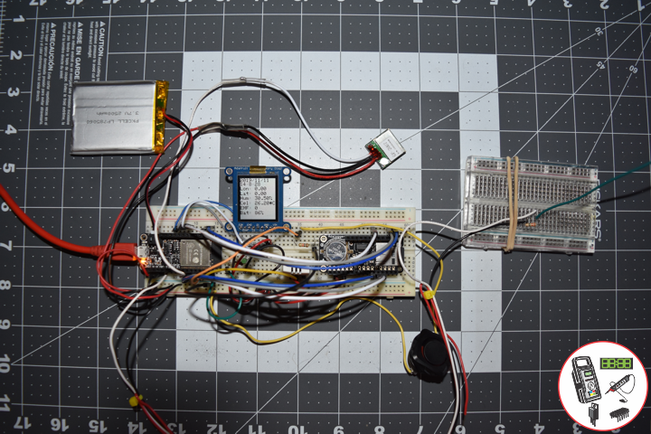
——
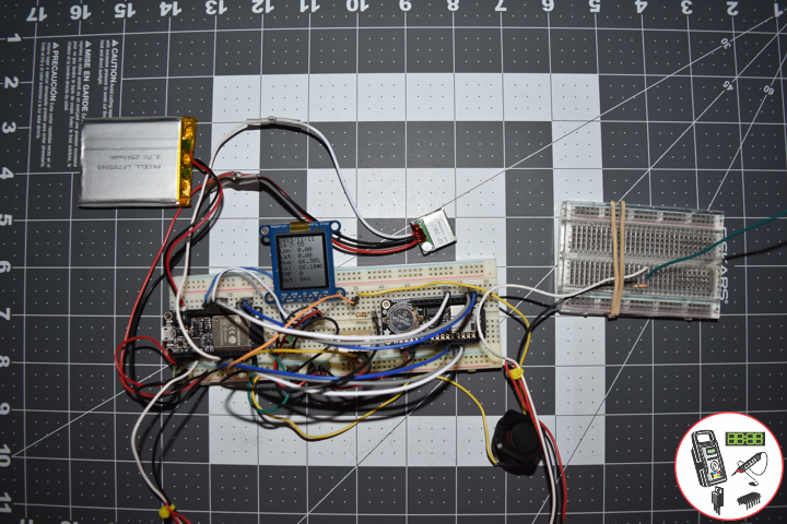
——
Lithium Ion Battery – 2.5Ah
These are very slim, extremely light weight batteries based on Lithium Ion chemistry. Each cell outputs a nominal 3.7V at 2500mAh. Comes terminated with a standard 2-pin JST-PH connector – 2mm spacing between pins. These batteries require special charging. Do not attempt to charge these with anything but a specialized Lithium Polymer charger.
DL1911Mk01
1 x Adafruit HUZZAH32 ESP32 Feather
1 x Adafruit SHARP Memory Display
1 x Adafruit Adalogger FeatherWing – RTC + SD
1 x CR1220 12mm Lithium Battery
1 x 8Gb Micro SD Card
1 x RHT03 Humidity and Temperature Sensor
1 x GPS Receiver GP-20U
1 x LED Green
1 x Rocker Switches
1 x 100 Ohm
1 x 10K Ohm
1 x 3.3M Ohm
1 x Antenna
1 x Lithium Ion Battery – 2.5Ah
14 x Jumper Wires 3″ M/M
6 x Jumper Wires 6″ M/M
2 x Wire
1 x Full-Size Breadboard
1 x Breadboard
1 x SparkFun Cerberus USB Cable
Adafruit HUZZAH32 ESP32 Feather
LG1 – Digital 21
RO1 – Digital 16
RHT – Digital 17
SCK – Digital 13
MOS – Digital 12
SSD – Digital 27
SDA – Digital 23
SCL – Digital 22
SD1 – Digital 33
SC2 – Digital 5
MO2 – Digital 18
MI2 – Digital 19
GPS – Digital 4
EMF – Analog A0
BAT – Analog A13
GND – GND
VIN – +3.3V
DL1911Mk01.ino
// ***** Don Luc Electronics *****
// Software Version Information
// Project #11: HUZZAH32 ESP32 Feather - LiPo 2.5Ah - Mk10
// 11-01
// DL1911Mk01p.ino 11-10
// Adafruit HUZZAH32 ESP32 Feather Board
// SHARP Display
// LED Green
// Adalogger FeatherWing - RTC + SD
// EEPROM
// RHT03 Humidity and Temperature Sensor
// Rocker Switches
// GPS Receiver
// EMF Meter (Single Axis)
// Lithium Ion Battery - 2.5Ah

// include Library Code
// SHARP Memory Display
#include <Adafruit_SharpMem.h>
#include <Adafruit_GFX.h>
// Date and Time
#include "RTClib.h"
// EEPROM library to read EEPROM with unique ID for unit
#include "EEPROM.h"
// RHT Humidity and Temperature Sensor
#include <SparkFun_RHT03.h>
// SD Card
#include "FS.h"
#include "SD.h"
#include "SPI.h"
// GPS Receiver
#include <TinyGPS++.h>
#include <HardwareSerial.h>

// SHARP Memory Display
// any pins can be used
#define SHARP_SCK  13
#define SHARP_MOSI 12
#define SHARP_SS   27
// Set the size of the display here, e.g. 144x168!
Adafruit_SharpMem display(SHARP_SCK, SHARP_MOSI, SHARP_SS, 144, 168);
// The currently-available SHARP Memory Display (144x168 pixels)
// requires > 4K of microcontroller RAM; it WILL NOT WORK on Arduino Uno
// or other <4K "classic" devices!
#define BLACK 0
#define WHITE 1
int minorHalfSize; // 1/2 of lesser of display width or height

// LED Green
int iLEDGreen =  21;                 // LED Green

// PCF8523 Precision RTC
RTC_PCF8523 rtc;
String dateRTC = "";
String timeRTC = "";

// RHT Humidity and Temperature Sensor
const int RHT03_DATA_PIN = 17;          // RHT03 data pin Digital 17
RHT03 rht;                              // This creates a RTH03 object, which we'll use to interact with the sensor
float latestHumidity;
float latestTempC;
float latestTempF;

// SD Card
const int chipSelect = 33;              // SD Card
String zzzzzz = "";

// Rocker Switches
int iRow1 = 16;                         // Rocker Switches Digital 16
int iRow1State = 0;                     // Variable for reading the pushbutton status

// ESP32 HardwareSerial
HardwareSerial tGPS(2);

// GPS Receiver
#define gpsRXPIN 4
#define gpsTXPIN 36                     // This one is unused and doesnt have a conection
// The TinyGPS++ object
TinyGPSPlus gps;
float TargetLat;
float TargetLon;
int Status = 0;

// EMF Meter (Single Axis)
#define NUMREADINGS 15                    // Raise this number to increase data smoothing
int senseLimit = 15;                      // Raise this number to decrease sensitivity (up to 1023 max)
int val = 0;                              // Val
int iEMF = A0;                            // EMF Meter
int readings[ NUMREADINGS ];              // Readings from the analog input
int ind = 0;                              // Index of the current reading
int total = 0;                            // Running total
int average = 0;                          // Final average of the probe reading
int iEMFDis = 0;
int iEMFRect = 0;

// LiPo Battery
const int bat = A13;                      // LiPo Battery
uint16_t vbat = 0;
int iBat = 0;

// The current address in the EEPROM (i.e. which byte
// we're going to  read to next)
#define EEPROM_SIZE 64
String sver = "11-1.p";
// Unit ID information
String uid = "";

void loop() {

  // Receives NEMA data from GPS receiver
  // This sketch displays information every time a new sentence is correctly encoded.
  while ( tGPS.available() > 0)
    if (gps.encode( tGPS.read() ))
    {
     displayInfo();
    }

  if (millis() > 5000 && gps.charsProcessed() < 10)
  {
    while(true);
  }

  // Date and Time
  isRTC();

  // RHT03 Humidity and Temperature Sensor
  isRHT03();

  // SHARP Memory Display On
  isDisplayOn();

  // Rocker Switched
  // Read the state of the iRow1 value
  iRow1State = digitalRead(iRow1);

  // EMF Meter (Single Axis)
  isEMF();

  // LiPo Battery
  isBattery();

  // Check if the pushbutton is pressed. If it is, the buttonState is HIGH:
  if (iRow1State == HIGH) {

    // iLEDGreen
    digitalWrite(iLEDGreen,  HIGH );
    // SD Card
    isSD();

  } else {

    // iLEDGreen
    digitalWrite(iLEDGreen,  LOW );

  }

  // Delay
  delay( 1000 );

}
getBattery.ino
// LiPo Battery
void isBattery() {

  // Battery
  vbat = analogRead(bat);
  vbat = vbat / 2;

  iBat = map( vbat, 1, 1064, 1, 100);

}
getDisplay.ino
// SHARP Memory Display On
void isDisplayOn() {

    // Clear Display
    display.clearDisplay();
    // text display date, time, LED on
    display.setRotation(4);
    display.setTextSize(2);
    display.setTextColor(BLACK);
    display.setCursor(0,1);
    display.println( dateRTC );
    display.setCursor(0,17);
    display.println( timeRTC );
    display.setCursor(0,35);
    display.print("Lon: ");
    display.println( TargetLon );
    display.setCursor(0,55);
    display.print("Lat: ");
    display.println( TargetLat );
    display.setCursor(0,74);
    display.print("Hum: ");
    display.print( latestHumidity );
    display.println("%");
    display.setCursor(0,94);
    display.print("Cel: ");
    display.print( latestTempC );
    display.println("*C");
    display.setCursor(0,114);
    display.print("EMF: ");
    display.println( iEMFDis );
    display.setCursor(0,134);
    display.print("Bat: ");
    display.print( iBat );
    display.println( "%" );
    display.refresh();

}
// SHARP Memory Display - UID
void isDisplayUID() {

    // text display EEPROM
    display.setRotation(4);
    display.setTextSize(2);
    display.setTextColor(BLACK);
    display.setCursor(0,20);
    display.print( "UID: " );
    display.println( uid );
   // display.setTextSize();
    display.setTextColor(BLACK);
    display.setCursor(0,45);
    display.print( "VER: ");
    display.println( sver  );
    display.refresh();
    delay( 100 );

}
getEEPROM.ino
// EEPROM
void GetUID()
{

  // Get unit ID
  uid = "";
  for (int x = 0; x < 5; x++)
  {
    uid = uid + char(EEPROM.read(x));
  }

}
getEMF.ino
// EMF Meter (Single Axis)
// setupEMF
void setupEMF() {

  // EMF Meter (Single Axis)
  pinMode( iEMF, OUTPUT ); // EMF Meter
  for (int i = 0; i < NUMREADINGS; i++){
    readings[ i ] = 0;     // Initialize all the readings to 0
  }

}
// isEMF
void isEMF(){

  // Probe
  val = analogRead( iEMF );                    // Take a reading from the probe

  if( val >= 1 ){                              // If the reading isn't zero, proceed

    val = constrain( val, 1, senseLimit );     // Turn any reading higher than the senseLimit value into the senseLimit value
    val = map( val, 1, senseLimit, 1, 1023 );  // Remap the constrained value within a 1 to 1023 range

    total -= readings[ ind ];                  // Subtract the last reading
    readings[ ind ] = val;                     // Read from the sensor
    total += readings[ ind ];                  // Add the reading to the total
    ind = ( ind + 1 );                         // Advance to the next index

    if ( ind >= NUMREADINGS ) {                // If we're at the end of the array...
      ind = 0;                                 // ...wrap around to the beginning
    }

    average = total / NUMREADINGS;             // Calculate the average


   // average = val;
  }
  else
  {

    iEMFRect = 0;
    val = 0;
    average = 0;

  }

  iEMFDis = average;
  iEMFRect = map( average, 1, 1023, 1, 144 );

}
getGPS.ino
// GPS Receiver
void setupGPS() {

  // Setup GPS
  tGPS.begin(  9600 , SERIAL_8N1, gpsRXPIN, gpsTXPIN );

}
// GPS Vector Pointer Target
void displayInfo()
{

  // Location
  if (gps.location.isValid())
  {

    TargetLat = gps.location.lat();
    TargetLon = gps.location.lng();
    Status = 2;

  }
  else
  {

    Status = 0;

  }

}
getRHT.ino
// RHT03 Humidity and Temperature Sensor
void isRHT03(){

  // Call rht.update() to get new humidity and temperature values from the sensor.
  int updateRet = rht.update();

  // The humidity(), tempC(), and tempF() functions can be called -- after
  // a successful update() -- to get the last humidity and temperature value
  latestHumidity = rht.humidity();
  latestTempC = rht.tempC();
  latestTempF = rht.tempF();

}
getRTCpcf8523.ino
// PCF8523 Precision RTC
void setupRTC() {

  // pcf8523 Precision RTC
  if (! rtc.begin()) {
    while (1);
  }
  if (! rtc.initialized()) {
    // Following line sets the RTC to the date & time this sketch was compiled
    rtc.adjust(DateTime(F(__DATE__), F(__TIME__)));
    // This line sets the RTC with an explicit date & time, for example to set
    // January 21, 2014 at 3am you would call:
    // rtc.adjust(DateTime(2018, 9, 29, 12, 17, 0));
  }

}
// Date and Time RTC
void isRTC () {

  // Date and Time
  DateTime now = rtc.now();
  // Date
  dateRTC = now.year(), DEC;
  dateRTC = dateRTC + "/";
  dateRTC = dateRTC + now.month(), DEC;
  dateRTC = dateRTC + "/";
  dateRTC = dateRTC + now.day(), DEC;
  // Time
  timeRTC = now.hour(), DEC;
  timeRTC = timeRTC + ":";
  timeRTC = timeRTC + now.minute(), DEC;
  timeRTC = timeRTC + ":";
  timeRTC = timeRTC + now.second(), DEC;

}
getSD.ino
// SD Card
void setupSD() {

  // SD Card
    pinMode( chipSelect , OUTPUT );
    if(!SD.begin( chipSelect )){
        ;
        return;
    }
    uint8_t cardType = SD.cardType();

    if(cardType == CARD_NONE){
        ;
        return;
    }

    //Serial.print("SD Card Type: ");
    if(cardType == CARD_MMC){
        ;
    } else if(cardType == CARD_SD){
        ;
    } else if(cardType == CARD_SDHC){
        ;
    } else {
        ;
    }

    uint64_t cardSize = SD.cardSize() / (1024 * 1024);

}
// SD Card
void isSD() {

  zzzzzz = "";

  zzzzzz = uid + "|" + sver + "|" + dateRTC + "|" + timeRTC + "|" + Status + "|" + TargetLon + "|" + TargetLat + "|" + latestHumidity + "|" + latestTempC + "|" + latestTempF + "|" + average + "|\r";

  char msg[zzzzzz.length() + 1];

  zzzzzz.toCharArray(msg, zzzzzz.length() + 1);

  appendFile(SD, "/espdata.txt", msg );

}
// List Dir
void listDir(fs::FS &fs, const char * dirname, uint8_t levels){
    dirname;
    File root = fs.open(dirname);
    if(!root){
        return;
    }
    if(!root.isDirectory()){
        return;
    }

    File file = root.openNextFile();
    while(file){
        if(file.isDirectory()){
            file.name();
            if(levels){
                listDir(fs, file.name(), levels -1);
            }
        } else {
            file.name();
            file.size();
        }
        file = root.openNextFile();
    }
}
// Write File
void writeFile(fs::FS &fs, const char * path, const char * message){
    path;
    File file = fs.open(path, FILE_WRITE);
    if(!file){
        return;
    }
    if(file.print(message)){
        ;
    } else {
        ;
    }
    file.close();
}
// Append File
void appendFile(fs::FS &fs, const char * path, const char * message){
    //Serial.printf("Appending to file: %s\n", path);
    path;
    File file = fs.open(path, FILE_APPEND);
    if(!file){
        return;
    }
    if(file.print(message)){
        ;
    } else {
        ;
    }
    file.close();
}
setup.ino
// Setup
void setup() {

  // EEPROM with unique ID
  EEPROM.begin(EEPROM_SIZE);

  // Get Unit ID
  GetUID();

  // GPS Receiver
  // Setup GPS
  setupGPS();

  // SHARP Display start & clear the display
  display.begin();
  display.clearDisplay();

  isDisplayUID();

  delay( 5000 );

  // Initialize the LED Green
  pinMode(iLEDGreen, OUTPUT);

  // PCF8523 Precision RTC
  setupRTC();

  // Date and Time RTC
  isRTC();

  // RHT03 Humidity and Temperature Sensor
  // Call rht.begin() to initialize the sensor and our data pin
  rht.begin(RHT03_DATA_PIN);

  // SD Card
  setupSD();

  // Rocker Switches
  pinMode(iRow1, INPUT);

  // EMF Meter (Single Axis)
  setupEMF();

}
Follow Us
Web: https://www.donluc.com/
Web: http://neosteamlabs.com/
Web: http://www.jlpconsultants.com/
YouTube: https://www.youtube.com/channel/UC5eRjrGn1CqkkGfZy0jxEdA
Facebook: https://www.facebook.com/neosteam.labs.9/
Instagram: https://www.instagram.com/neosteamlabs/
Pinterest: https://www.pinterest.com/NeoSteamLabs/
Twitter: https://twitter.com/labs_steam
Etsy: https://www.etsy.com/shop/NeoSteamLabs
Don Luc
Project #11: ESP32 Feather – EMF Meter – Mk09
——
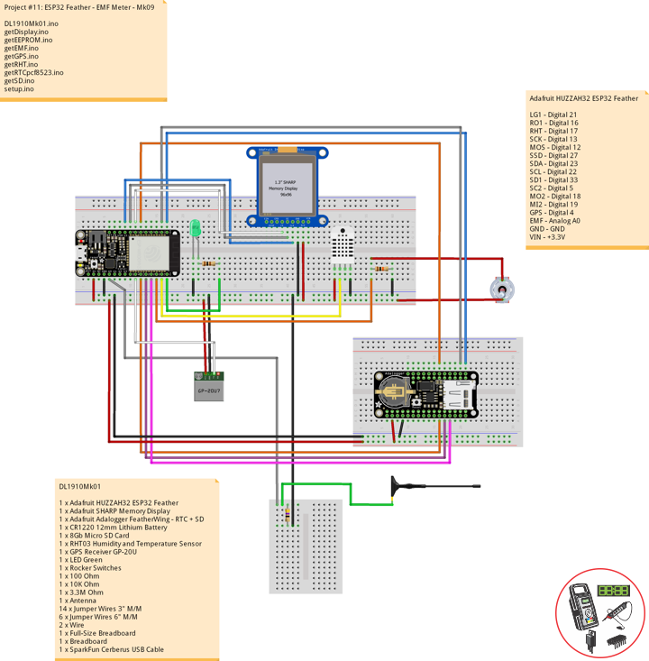
——
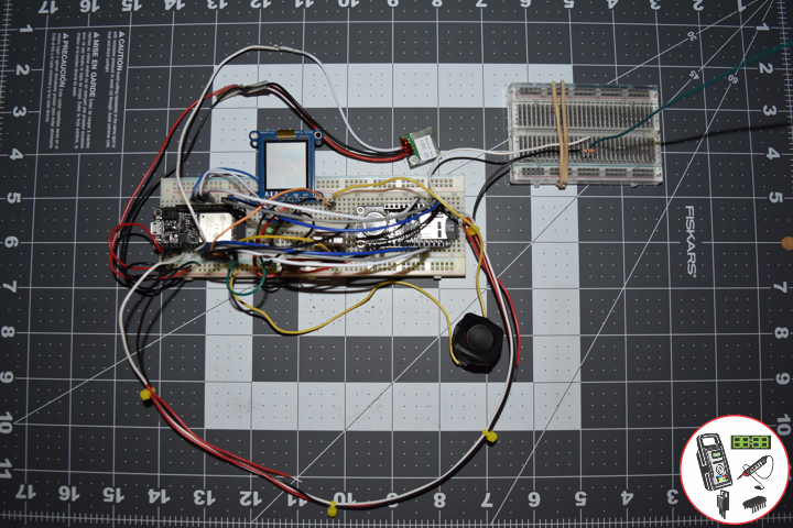
——
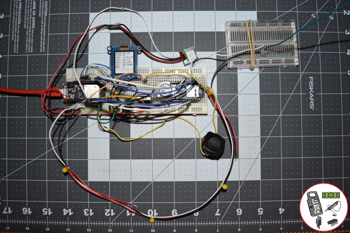
——
EMF Meter
EMF measurements are measurements of ambient electromagnetic fields that are performed using particular sensors or probes, such as EMF meters. These probes can be generally considered as antennas although with different characteristics. In fact probes should not perturb the electromagnetic field and must prevent coupling and reflection as much as possible in order to obtain precise results.
EMF probes may respond to fields only on one axis. Amplified, active, probes can improve measurement precision and sensitivity but their active components may limit their speed of response.
DL1910Mk01
1 x Adafruit HUZZAH32 ESP32 Feather
1 x Adafruit SHARP Memory Display
1 x Adafruit Adalogger FeatherWing – RTC + SD
1 x CR1220 12mm Lithium Battery
1 x 8Gb Micro SD Card
1 x RHT03 Humidity and Temperature Sensor
1 x GPS Receiver GP-20U
1 x LED Green
1 x Rocker Switches
1 x 100 Ohm
1 x 10K Ohm
1 x 3.3M Ohm
1 x Antenna
14 x Jumper Wires 3″ M/M
6 x Jumper Wires 6″ M/M
2 x Wire
1 x Full-Size Breadboard
1 x Breadboard
1 x SparkFun Cerberus USB Cable
Adafruit HUZZAH32 ESP32 Feather
LG1 – Digital 21
RO1 – Digital 16
RHT – Digital 17
SCK – Digital 13
MOS – Digital 12
SSD – Digital 27
SDA – Digital 23
SCL – Digital 22
SD1 – Digital 33
SC2 – Digital 5
MO2 – Digital 18
MI2 – Digital 19
GPS – Digital 4
EMF – Analog A0
GND – GND
VIN – +3.3V
DL1910Mk01.ino
// ***** Don Luc Electronics *****
// Software Version Information
// Project #11: HUZZAH32 ESP32 Feather - EMF - Mk09
// 10-01
// DL1910Mk01p.ino 11-09
// Adafruit HUZZAH32 ESP32 Feather Board
// SHARP Display
// LED Green
// Adalogger FeatherWing - RTC + SD
// EEPROM
// RHT03 Humidity and Temperature Sensor
// Rocker Switches
// GPS Receiver
// EMF Meter (Single Axis)

// include Library Code
// SHARP Memory Display
#include <Adafruit_SharpMem.h>
#include <Adafruit_GFX.h>
// Date and Time
#include "RTClib.h"
// EEPROM library to read EEPROM with unique ID for unit
#include "EEPROM.h"
// RHT Humidity and Temperature Sensor
#include <SparkFun_RHT03.h>
// SD Card
#include "FS.h"
#include "SD.h"
#include "SPI.h"
// GPS Receiver
#include <TinyGPS++.h>
#include <HardwareSerial.h>

// SHARP Memory Display
// any pins can be used
#define SHARP_SCK  13
#define SHARP_MOSI 12
#define SHARP_SS   27
// Set the size of the display here, e.g. 144x168!
Adafruit_SharpMem display(SHARP_SCK, SHARP_MOSI, SHARP_SS, 144, 168);
// The currently-available SHARP Memory Display (144x168 pixels)
// requires > 4K of microcontroller RAM; it WILL NOT WORK on Arduino Uno
// or other <4K "classic" devices!
#define BLACK 0
#define WHITE 1
int minorHalfSize; // 1/2 of lesser of display width or height

// LED Green
int iLEDGreen =  21;                 // LED Green

// PCF8523 Precision RTC
RTC_PCF8523 rtc;
String dateRTC = "";
String timeRTC = "";

// RHT Humidity and Temperature Sensor
const int RHT03_DATA_PIN = 17;          // RHT03 data pin Digital 17
RHT03 rht;                              // This creates a RTH03 object, which we'll use to interact with the sensor
float latestHumidity;
float latestTempC;
float latestTempF;

// SD Card
const int chipSelect = 33;              // SD Card
String zzzzzz = "";

// Rocker Switches
int iRow1 = 16;                         // Rocker Switches Digital 16
int iRow1State = 0;                     // Variable for reading the pushbutton status

// ESP32 HardwareSerial
HardwareSerial tGPS(2);

// GPS Receiver
#define gpsRXPIN 4
#define gpsTXPIN 36                     // This one is unused and doesnt have a conection
// The TinyGPS++ object
TinyGPSPlus gps;
float TargetLat;
float TargetLon;
int Status = 0;

// EMF Meter (Single Axis)
#define NUMREADINGS 15                    // Raise this number to increase data smoothing
int senseLimit = 15;                      // Raise this number to decrease sensitivity (up to 1023 max)
int val = 0;                              // Val
int iEMF = A0;                            // EMF Meter
int readings[ NUMREADINGS ];              // Readings from the analog input
int ind = 0;                              // Index of the current reading
int total = 0;                            // Running total
int average = 0;                          // Final average of the probe reading
int iEMFDis = 0;
int iEMFRect = 0;

// The current address in the EEPROM (i.e. which byte
// we're going to  read to next)
#define EEPROM_SIZE 64
String sver = "10-1.p";
// Unit ID information
String uid = "";

void loop() {

  // Receives NEMA data from GPS receiver
  // This sketch displays information every time a new sentence is correctly encoded.
  while ( tGPS.available() > 0)
    if (gps.encode( tGPS.read() ))
    {
     displayInfo();
    }

  if (millis() > 5000 && gps.charsProcessed() < 10)
  {
    while(true);
  }

  // Date and Time
  isRTC();

  // RHT03 Humidity and Temperature Sensor
  isRHT03();

  // SHARP Memory Display On
  isDisplayOn();

  // Rocker Switched
  // Read the state of the iRow1 value
  iRow1State = digitalRead(iRow1);

  // EMF Meter (Single Axis)
  isEMF();

  // Check if the pushbutton is pressed. If it is, the buttonState is HIGH:
  if (iRow1State == HIGH) {

    // iLEDGreen
    digitalWrite(iLEDGreen,  HIGH );
    // SD Card
    isSD();

  } else {

    // iLEDGreen
    digitalWrite(iLEDGreen,  LOW );

  }

  // Delay
  delay( 1000 );

}
getDisplay.ino
// SHARP Memory Display On
void isDisplayOn() {

    // Clear Display
    display.clearDisplay();
    // text display date, time, LED on
    display.setRotation(4);
    display.setTextSize(2);
    display.setTextColor(BLACK);
    display.setCursor(0,1);
    display.println( dateRTC );
    display.setCursor(0,17);
    display.println( timeRTC );
    //display.setTextSize(2);
    display.setCursor(0,35);
    display.print("Lon: ");
    display.println( TargetLon );
    display.setCursor(0,55);
    display.print("Lat: ");
    display.println( TargetLat );
    display.setCursor(0,74);
    display.print("Hum: ");
    display.print( latestHumidity );
    display.println("%");
    display.setCursor(0,94);
    display.print("Cel: ");
    display.print( latestTempC );
    display.println("*C");
    display.setCursor(0,114);
    display.print("EMF: ");
    display.println( iEMFDis );
    display.setCursor(0,134);
    display.setTextSize(1);
    display.println( "0  1 2 3 4 5 6 7 8 9  10" );
    display.setCursor(0,144);
    display.drawRect(0, 144, iEMFRect , display.height(), BLACK);
    display.fillRect(0, 144, iEMFRect , display.height(), BLACK);
    display.refresh();

}
// SHARP Memory Display - UID
void isDisplayUID() {

    // text display EEPROM
    display.setRotation(4);
    display.setTextSize(2);
    display.setTextColor(BLACK);
    display.setCursor(0,20);
    display.print( "UID: " );
    display.println( uid );
   // display.setTextSize();
    display.setTextColor(BLACK);
    display.setCursor(0,45);
    display.print( "VER: ");
    display.println( sver  );
    display.refresh();
    delay( 100 );

}
getEEPROM.ino
// EEPROM
void GetUID()
{

  // Get unit ID
  uid = "";
  for (int x = 0; x < 5; x++)
  {
    uid = uid + char(EEPROM.read(x));
  }

}
getEMF.ino
// EMF Meter (Single Axis)
// setupEMF
void setupEMF() {

  // EMF Meter (Single Axis)
  pinMode( iEMF, OUTPUT ); // EMF Meter
  for (int i = 0; i < NUMREADINGS; i++){
    readings[ i ] = 0;     // Initialize all the readings to 0
  }

}
// isEMF
void isEMF(){

  // Probe
  val = analogRead( iEMF );                    // Take a reading from the probe

  if( val >= 1 ){                              // If the reading isn't zero, proceed

    val = constrain( val, 1, senseLimit );     // Turn any reading higher than the senseLimit value into the senseLimit value
    val = map( val, 1, senseLimit, 1, 1023 );  // Remap the constrained value within a 1 to 1023 range

    total -= readings[ ind ];                  // Subtract the last reading
    readings[ ind ] = val;                     // Read from the sensor
    total += readings[ ind ];                  // Add the reading to the total
    ind = ( ind + 1 );                         // Advance to the next index

    if ( ind >= NUMREADINGS ) {                // If we're at the end of the array...
      ind = 0;                                 // ...wrap around to the beginning
    }

    average = total / NUMREADINGS;             // Calculate the average

  }
  else
  {

    iEMFRect = 0;
    val = 0;
    average = 0;

  }

  iEMFDis = average;
  iEMFRect = map( average, 1, 1023, 1, 144 );

}
getGPS.ino
// GPS Receiver
void setupGPS() {

  // Setup GPS
  tGPS.begin(  9600 , SERIAL_8N1, gpsRXPIN, gpsTXPIN );

}
// GPS Vector Pointer Target
void displayInfo()
{

  // Location
  if (gps.location.isValid())
  {

    TargetLat = gps.location.lat();
    TargetLon = gps.location.lng();
    Status = 2;

  }
  else
  {

    Status = 0;

  }

}
getRHT.ino
// RHT03 Humidity and Temperature Sensor
void isRHT03(){

  // Call rht.update() to get new humidity and temperature values from the sensor.
  int updateRet = rht.update();

  // The humidity(), tempC(), and tempF() functions can be called -- after
  // a successful update() -- to get the last humidity and temperature value
  latestHumidity = rht.humidity();
  latestTempC = rht.tempC();
  latestTempF = rht.tempF();

}
getRTCpcf8523.ino
// PCF8523 Precision RTC
void setupRTC() {

  // pcf8523 Precision RTC
  if (! rtc.begin()) {
    while (1);
  }
  if (! rtc.initialized()) {
    // Following line sets the RTC to the date & time this sketch was compiled
    rtc.adjust(DateTime(F(__DATE__), F(__TIME__)));
    // This line sets the RTC with an explicit date & time, for example to set
    // January 21, 2014 at 3am you would call:
    // rtc.adjust(DateTime(2018, 9, 29, 12, 17, 0));
  }

}
// Date and Time RTC
void isRTC () {

  // Date and Time
  DateTime now = rtc.now();
  // Date
  dateRTC = now.year(), DEC;
  dateRTC = dateRTC + "/";
  dateRTC = dateRTC + now.month(), DEC;
  dateRTC = dateRTC + "/";
  dateRTC = dateRTC + now.day(), DEC;
  // Time
  timeRTC = now.hour(), DEC;
  timeRTC = timeRTC + ":";
  timeRTC = timeRTC + now.minute(), DEC;
  timeRTC = timeRTC + ":";
  timeRTC = timeRTC + now.second(), DEC;

}
getSD.ino
// SD Card
void setupSD() {

  // SD Card
    pinMode( chipSelect , OUTPUT );
    if(!SD.begin( chipSelect )){
        ;
        return;
    }
    uint8_t cardType = SD.cardType();

    if(cardType == CARD_NONE){
        ;
        return;
    }

    //Serial.print("SD Card Type: ");
    if(cardType == CARD_MMC){
        ;
    } else if(cardType == CARD_SD){
        ;
    } else if(cardType == CARD_SDHC){
        ;
    } else {
        ;
    }

    uint64_t cardSize = SD.cardSize() / (1024 * 1024);

}
// SD Card
void isSD() {

  zzzzzz = "";

  zzzzzz = uid + "|" + sver + "|" + dateRTC + "|" + timeRTC + "|" + Status + "|" + TargetLon + "|" + TargetLat + "|" + latestHumidity + "|" + latestTempC + "|" + latestTempF + "|" + average + "|\r";

  char msg[zzzzzz.length() + 1];

  zzzzzz.toCharArray(msg, zzzzzz.length() + 1);

  appendFile(SD, "/espdata.txt", msg );

}
// List Dir
void listDir(fs::FS &fs, const char * dirname, uint8_t levels){
    dirname;
    File root = fs.open(dirname);
    if(!root){
        return;
    }
    if(!root.isDirectory()){
        return;
    }

    File file = root.openNextFile();
    while(file){
        if(file.isDirectory()){
            file.name();
            if(levels){
                listDir(fs, file.name(), levels -1);
            }
        } else {
            file.name();
            file.size();
        }
        file = root.openNextFile();
    }
}
// Write File
void writeFile(fs::FS &fs, const char * path, const char * message){
    path;
    File file = fs.open(path, FILE_WRITE);
    if(!file){
        return;
    }
    if(file.print(message)){
        ;
    } else {
        ;
    }
    file.close();
}
// Append File
void appendFile(fs::FS &fs, const char * path, const char * message){
    //Serial.printf("Appending to file: %s\n", path);
    path;
    File file = fs.open(path, FILE_APPEND);
    if(!file){
        return;
    }
    if(file.print(message)){
        ;
    } else {
        ;
    }
    file.close();
}
setup.ino
// Setup
void setup() {

  // EEPROM with unique ID
  EEPROM.begin(EEPROM_SIZE);

  // Get Unit ID
  GetUID();

  // GPS Receiver
  // Setup GPS
  setupGPS();

  // SHARP Display start & clear the display
  display.begin();
  display.clearDisplay();

  isDisplayUID();

  delay( 5000 );

  // Initialize the LED Green
  pinMode(iLEDGreen, OUTPUT);

  // PCF8523 Precision RTC
  setupRTC();

  // Date and Time RTC
  isRTC();

  // RHT03 Humidity and Temperature Sensor
  // Call rht.begin() to initialize the sensor and our data pin
  rht.begin(RHT03_DATA_PIN);

  // SD Card
  setupSD();

  // Rocker Switches
  pinMode(iRow1, INPUT);

  // EMF Meter (Single Axis)
  setupEMF();

}
Follow Us
Web: https://www.donluc.com/
Web: http://neosteamlabs.com/
Web: http://www.jlpconsultants.com/
YouTube: https://www.youtube.com/channel/UC5eRjrGn1CqkkGfZy0jxEdA
Facebook: https://www.facebook.com/neosteam.labs.9/
Instagram: https://www.instagram.com/neosteamlabs/
Pinterest: https://www.pinterest.com/NeoSteamLabs/
Twitter: https://twitter.com/labs_steam
Etsy: https://www.etsy.com/shop/NeoSteamLabs
Don Luc
Project #11: ESP32 Feather – ADXL335 – Mk08
ESP32 Feather – ADXL335
——
——
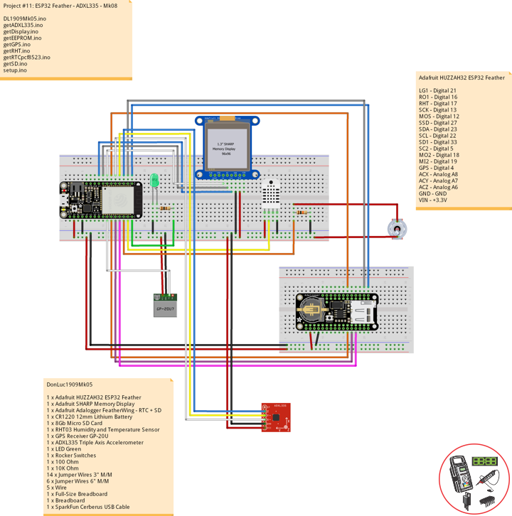
——
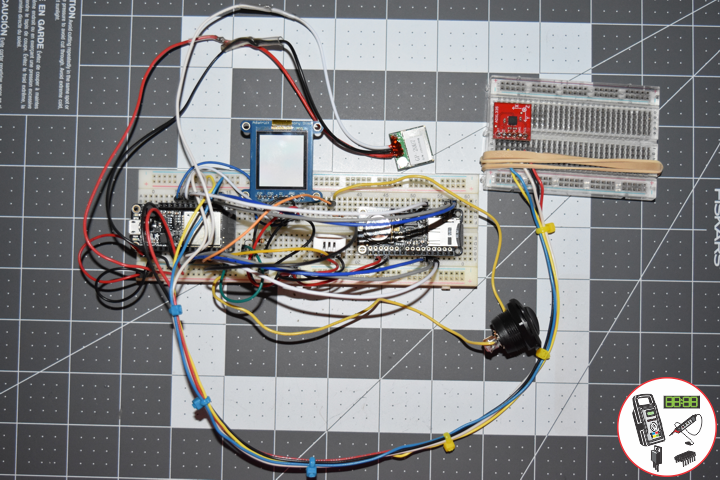
——
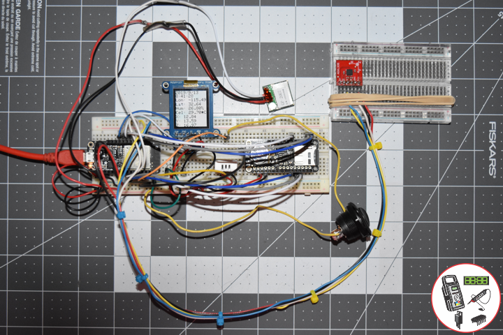
——
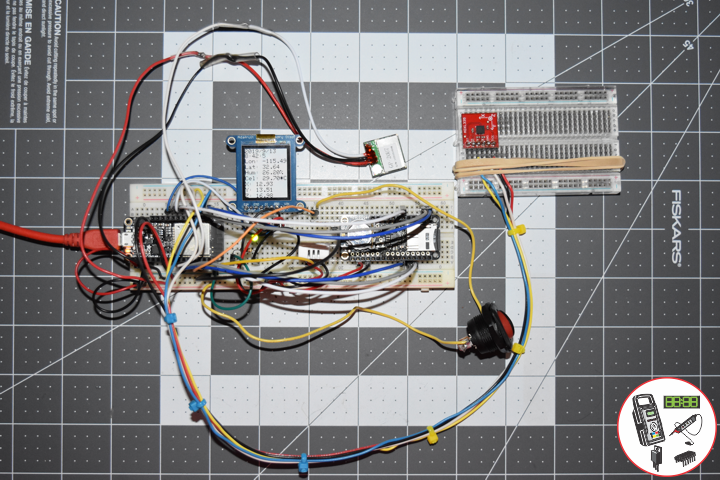
——
ADXL335 Triple Axis Accelerometer
Breakout board for the 3 axis ADXL335 from Analog Devices. This is the latest in a long, proven line of analog sensors – the holy grail of accelerometers. The ADXL335 is a triple axis MEMS accelerometer with extremely low noise and power consumption – only 320uA! The sensor has a full sensing range of +/-3g.
DonLuc1909Mk05
1 x Adafruit HUZZAH32 ESP32 Feather
1 x Adafruit SHARP Memory Display
1 x Adafruit Adalogger FeatherWing – RTC + SD
1 x CR1220 12mm Lithium Battery
1 x 8Gb Micro SD Card
1 x RHT03 Humidity and Temperature Sensor
1 x GPS Receiver GP-20U
1 x ADXL335 Triple Axis Accelerometer
1 x LED Green
1 x Rocker Switches
1 x 100 Ohm
1 x 10K Ohm
14 x Jumper Wires 3″ M/M
6 x Jumper Wires 6″ M/M
5 x Wire
1 x Full-Size Breadboard
1 x Breadboard
1 x SparkFun Cerberus USB Cable
Adafruit HUZZAH32 ESP32 Feather
LG1 – Digital 21
RO1 – Digital 16
RHT – Digital 17
SCK – Digital 13
MOS – Digital 12
SSD – Digital 27
SDA – Digital 23
SCL – Digital 22
SD1 – Digital 33
SC2 – Digital 5
MO2 – Digital 18
MI2 – Digital 19
GPS – Digital 4
ACX – Analog A8
ACY – Analog A7
ACZ – Analog A6
GND – GND
VIN – +3.3V
DL1909Mk05.ino
// ***** Don Luc Electronics *****
// Software Version Information
// Project #11: HUZZAH32 ESP32 Feather - ADXL335 - Mk08
// 09-05
// DL1909Mk05p.ino 11-08
// Adafruit HUZZAH32 ESP32 Feather Board
// SHARP Display
// LED Green
// Adalogger FeatherWing - RTC + SD
// EEPROM
// RHT03 Humidity and Temperature Sensor
// Rocker Switches
// GPS Receiver
// ADXL335 Triple Axis Accelerometer

// include Library Code
// SHARP Memory Display
#include <Adafruit_SharpMem.h>
#include <Adafruit_GFX.h>
// Date and Time
#include "RTClib.h"
// EEPROM library to read EEPROM with unique ID for unit
#include "EEPROM.h"
// RHT Humidity and Temperature Sensor
#include <SparkFun_RHT03.h>
// SD Card
#include "FS.h"
#include "SD.h"
#include "SPI.h"
// GPS Receiver
#include <TinyGPS++.h>
#include <HardwareSerial.h>
// ADXL335 Triple Axis Accelerometer
#include <ADXL335.h>

// SHARP Memory Display
// any pins can be used
#define SHARP_SCK  13
#define SHARP_MOSI 12
#define SHARP_SS   27
// Set the size of the display here, e.g. 144x168!
Adafruit_SharpMem display(SHARP_SCK, SHARP_MOSI, SHARP_SS, 144, 168);
// The currently-available SHARP Memory Display (144x168 pixels)
// requires > 4K of microcontroller RAM; it WILL NOT WORK on Arduino Uno
// or other <4K "classic" devices!
#define BLACK 0
#define WHITE 1
int minorHalfSize; // 1/2 of lesser of display width or height

// LED Green
int iLEDGreen =  21;                 // LED Green

// PCF8523 Precision RTC
RTC_PCF8523 rtc;
String dateRTC = "";
String timeRTC = "";

// RHT Humidity and Temperature Sensor
const int RHT03_DATA_PIN = 17;          // RHT03 data pin Digital 17
RHT03 rht;                              // This creates a RTH03 object, which we'll use to interact with the sensor
float latestHumidity;
float latestTempC;
float latestTempF;

// SD Card
const int chipSelect = 33;              // SD Card
String zzzzzz = "";

// Rocker Switches
int iRow1 = 16;                         // Rocker Switches Digital 16
int iRow1State = 0;                     // Variable for reading the pushbutton status

// ESP32 HardwareSerial
HardwareSerial tGPS(2);

// GPS Receiver
#define gpsRXPIN 4
#define gpsTXPIN 36                     // This one is unused and doesnt have a conection
// The TinyGPS++ object
TinyGPSPlus gps;
float TargetLat;
float TargetLon;
int Status = 0;

// ADXL335 Triple Axis Accelerometer
const int pin_x = A8;
const int pin_y = A7;
const int pin_z = A6;
const float aref = 3.3;
ADXL335 accel(pin_x, pin_y, pin_z, aref);
String latestX = "";
String latestY = "";
String latestZ = "";

// The current address in the EEPROM (i.e. which byte
// we're going to  read to next)
#define EEPROM_SIZE 64
String sver = "9-5.p";
// Unit ID information
String uid = "";

void loop() {

  // Receives NEMA data from GPS receiver
  // This sketch displays information every time a new sentence is correctly encoded.
  while ( tGPS.available() > 0)
    if (gps.encode( tGPS.read() ))
    {
     displayInfo();
    }

  if (millis() > 5000 && gps.charsProcessed() < 10)
  {
    while(true);
  }

  // Date and Time
  isRTC();

  // RHT03 Humidity and Temperature Sensor
  isRHT03();

  // SHARP Memory Display On
  isDisplayOn();

  // Rocker Switched
  // Read the state of the iRow1 value
  iRow1State = digitalRead(iRow1);

  // ADXL335 Triple Axis Accelerometer
  getADXL335();

  // Check if the pushbutton is pressed. If it is, the buttonState is HIGH:
  if (iRow1State == HIGH) {

    // iLEDGreen
    digitalWrite(iLEDGreen,  HIGH );
    // SD Card
    isSD();

  } else {

    // iLEDGreen
    digitalWrite(iLEDGreen,  LOW );

  }

  // Delay
  delay( 1000 );

}
getADXL335.ino
// ADXL335 Triple Axis Accelerometer
void getADXL335()
{

  // This is required to update the values
  accel.update();

  // This tells us how long the string is
  int string_width;

  float x;
  float y;
  float z;

  x = accel.getX();
  y = accel.getY();
  // If the project is laying flat and top up the z axis reads ~1G
  z = accel.getZ();

  latestX = formatFloat(x, 2, &string_width);
  latestY = formatFloat(y, 2, &string_width);
  latestZ = formatFloat(z, 2, &string_width);

}
// Format float library
String formatFloat(double value, int places, int* string_width)
{

  // If value is positive infinity
  if (isinf(value) > 0)
  {
    return "+Inf";
  }

  // Arduino does not seem to have negative infinity
  // keeping this code block for reference
  // if value is negative infinity
  if(isinf(value) < 0)
  {
    return "-Inf";
  }

  // If value is not a number
  if(isnan(value) > 0)
  {
    return "NaN";
  }

  // Always include a space for the dot
  int num_width = 1;

  // If the number of decimal places is less than 1
  if (places < 1)
  {

    // Set places to 1
    places = 1;

    // And truncate the value
    value = (float)((int)value);

  }

  // Add the places to the right of the decimal
  num_width += places;

  // If the value does not contain an integral part
  if (value < 1.0 && value > -1.0)
  {

    // Add one for the integral zero
    num_width++;

  }
  else
  {

    // Get the integral part and get the number of places to the left of decimal
    num_width += ((int)log10(abs(value))) + 1;

  }

  // If the value in less than 0
  if (value < 0.0)
  {

    // Add a space for the minus sign
    num_width++;

  }

  // Make a string the size of the number plus 1 for string terminator
  char s[num_width + 1];

  // Put the string terminator at the end
  s[num_width] = '\0';

  // Initalize the array to all zeros
  for (int i = 0; i < num_width; i++)
  {

    s[i] = '0';

  }

  // Characters that are not changed by the function below will be zeros
  // set the out variable string width lets the caller know what we came up with
  *string_width = num_width;

  // Use the avr-libc function dtosrtf to format the value
  return String(dtostrf(value,num_width,places,s));

}
getDisplay.ino
// SHARP Memory Display On
void isDisplayOn() {

    // Clear Display
    display.clearDisplay();
    // text display date, time, LED on
    display.setRotation(4);
    display.setTextSize(2);
    display.setTextColor(BLACK);
    display.setCursor(0,1);
    display.println( dateRTC );
    display.setCursor(0,17);
    display.println( timeRTC );
    //display.setTextSize(2);
    display.setCursor(0,35);
    display.print("Lon: ");
    display.println( TargetLon );
    display.setCursor(0,55);
    display.print("Lat: ");
    display.println( TargetLat );
    display.setCursor(0,74);
    display.print("Hum: ");
    display.print( latestHumidity );
    display.println("%");
    display.setCursor(0,94);
    display.print("Cel: ");
    display.print( latestTempC );
    display.println("*C");
    display.setCursor(0,114);
    display.print("X: ");
    display.println( latestX );
    display.setCursor(0,134);
    display.print("Y: ");
    display.println( latestY );
    display.setCursor(0,154);
    display.print("Z: ");
    display.println( latestZ );
    display.refresh();

}
// SHARP Memory Display - UID
void isDisplayUID() {

    // text display EEPROM
    display.setRotation(4);
    display.setTextSize(2);
    display.setTextColor(BLACK);
    display.setCursor(0,20);
    display.print( "UID: " );
    display.println( uid );
   // display.setTextSize();
    display.setTextColor(BLACK);
    display.setCursor(0,45);
    display.print( "VER: ");
    display.println( sver  );
    display.refresh();
    delay( 100 );

}
getEEPROM.ino
// EEPROM
void GetUID()
{

  // Get unit ID
  uid = "";
  for (int x = 0; x < 5; x++)
  {
    uid = uid + char(EEPROM.read(x));
  }

}
getGPS.ino
// GPS Receiver
void setupGPS() {

  // Setup GPS
  tGPS.begin(  9600 , SERIAL_8N1, gpsRXPIN, gpsTXPIN );

}
// GPS Vector Pointer Target
void displayInfo()
{

  // Location
  if (gps.location.isValid())
  {

    TargetLat = gps.location.lat();
    TargetLon = gps.location.lng();
    Status = 2;

  }
  else
  {

    Status = 0;

  }

}
getRHT.ino
// RHT03 Humidity and Temperature Sensor
void isRHT03(){

  // Call rht.update() to get new humidity and temperature values from the sensor.
  int updateRet = rht.update();

  // The humidity(), tempC(), and tempF() functions can be called -- after
  // a successful update() -- to get the last humidity and temperature value
  latestHumidity = rht.humidity();
  latestTempC = rht.tempC();
  latestTempF = rht.tempF();

}
getRTCpcf8523.ino
// PCF8523 Precision RTC
void setupRTC() {

  // pcf8523 Precision RTC
  if (! rtc.begin()) {
    while (1);
  }
  if (! rtc.initialized()) {
    // Following line sets the RTC to the date & time this sketch was compiled
    rtc.adjust(DateTime(F(__DATE__), F(__TIME__)));
    // This line sets the RTC with an explicit date & time, for example to set
    // January 21, 2014 at 3am you would call:
    // rtc.adjust(DateTime(2018, 9, 29, 12, 17, 0));
  }

}
// Date and Time RTC
void isRTC () {

  // Date and Time
  DateTime now = rtc.now();
  // Date
  dateRTC = now.year(), DEC;
  dateRTC = dateRTC + "/";
  dateRTC = dateRTC + now.month(), DEC;
  dateRTC = dateRTC + "/";
  dateRTC = dateRTC + now.day(), DEC;
  // Time
  timeRTC = now.hour(), DEC;
  timeRTC = timeRTC + ":";
  timeRTC = timeRTC + now.minute(), DEC;
  timeRTC = timeRTC + ":";
  timeRTC = timeRTC + now.second(), DEC;

}
getSD.ino
// SD Card
void setupSD() {

  // SD Card
    pinMode( chipSelect , OUTPUT );
    if(!SD.begin( chipSelect )){
        ;
        return;
    }
    uint8_t cardType = SD.cardType();

    if(cardType == CARD_NONE){
        ;
        return;
    }

    //Serial.print("SD Card Type: ");
    if(cardType == CARD_MMC){
        ;
    } else if(cardType == CARD_SD){
        ;
    } else if(cardType == CARD_SDHC){
        ;
    } else {
        ;
    }

    uint64_t cardSize = SD.cardSize() / (1024 * 1024);

}
// SD Card
void isSD() {

  zzzzzz = "";

  zzzzzz = uid + "|" + sver + "|" + dateRTC + "|" + timeRTC + "|" + Status + "|" + TargetLon + "|" + TargetLat + "|" + latestHumidity + "|" + latestTempC + "|" + latestTempF + "|" + latestX + "|" + latestY + "|" + latestZ + "|\r";

  char msg[zzzzzz.length() + 1];

  zzzzzz.toCharArray(msg, zzzzzz.length() + 1);

  appendFile(SD, "/espdata.txt", msg );

}
// List Dir
void listDir(fs::FS &fs, const char * dirname, uint8_t levels){
    dirname;
    File root = fs.open(dirname);
    if(!root){
        return;
    }
    if(!root.isDirectory()){
        return;
    }

    File file = root.openNextFile();
    while(file){
        if(file.isDirectory()){
            file.name();
            if(levels){
                listDir(fs, file.name(), levels -1);
            }
        } else {
            file.name();
            file.size();
        }
        file = root.openNextFile();
    }
}
// Write File
void writeFile(fs::FS &fs, const char * path, const char * message){
    path;
    File file = fs.open(path, FILE_WRITE);
    if(!file){
        return;
    }
    if(file.print(message)){
        ;
    } else {
        ;
    }
    file.close();
}
// Append File
void appendFile(fs::FS &fs, const char * path, const char * message){
    //Serial.printf("Appending to file: %s\n", path);
    path;
    File file = fs.open(path, FILE_APPEND);
    if(!file){
        return;
    }
    if(file.print(message)){
        ;
    } else {
        ;
    }
    file.close();
}
setup.ino
// Setup
void setup() {

  // EEPROM with unique ID
  EEPROM.begin(EEPROM_SIZE);

  // Get Unit ID
  GetUID();

  // GPS Receiver
  // Setup GPS
  setupGPS();

  // SHARP Display start & clear the display
  display.begin();
  display.clearDisplay();

  isDisplayUID();

  delay( 5000 );

  // Initialize the LED Green
  pinMode(iLEDGreen, OUTPUT);

  // PCF8523 Precision RTC
  setupRTC();

  // Date and Time RTC
  isRTC();

  // RHT03 Humidity and Temperature Sensor
  // Call rht.begin() to initialize the sensor and our data pin
  rht.begin(RHT03_DATA_PIN);

  // SD Card
  setupSD();

  // Rocker Switches
  pinMode(iRow1, INPUT);

}
Follow Us
Web: https://www.donluc.com/
Web: http://neosteamlabs.com/
Web: http://www.jlpconsultants.com/
YouTube: https://www.youtube.com/channel/UC5eRjrGn1CqkkGfZy0jxEdA
Facebook: https://www.facebook.com/neosteam.labs.9/
Instagram: https://www.instagram.com/neosteamlabs/
Pinterest: https://www.pinterest.com/NeoSteamLabs/
Twitter: https://twitter.com/labs_steam
Etsy: https://www.etsy.com/shop/NeoSteamLabs
Don Luc