Microcontrollers
Microcontrollers
Raspberry Pi NoIR Camera V2.1
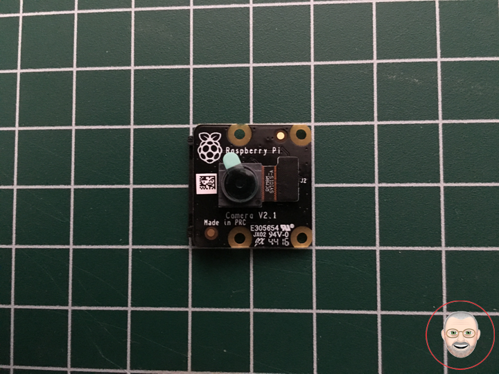
The infrared Camera Module v2 (Pi NoIR) has a Sony IMX219 8-megapixel sensor custom designed add-on board for Raspberry Pi, featuring a fixed focus lens. It’s capable of 3280 x 2464 pixel static images, and also support 1080p30, 720p60, and 640x480p60/90 video. The Pi NoIR gives you everything the regular Camera Module offers, with one difference: it does not employ an infrared filter. This means that pictures you take by daylight will look decidedly curious, but it gives you the ability to see in the dark with infrared lighting.
We bundle a little square of blue gel with the Pi NoIR “night vision”, which you can use with the camera to monitor the health of green plants. The Pi NoIR is very popular among wildlife hobbyists: with a few infrared LEDs, you can monitor what nocturnal animals are doing in your garden without disturbing them. It attaches to the Pi by way of one of the small sockets on the board’s upper surface and uses the dedicated CSi interface, designed especially for interfacing to cameras. The NoIR Camera has No InfraRed (NoIR) filter on the lens which makes it perfect for doing Infrared photography and taking pictures in low light (twilight) environments.
Features
Improved Resolution
* 8 megapixel native resolution high quality Sony IMX219 image sensor
* Cameras are capable of 3280 x 2464 pixel static images
Remaining High Quality
* Capture video at 1080p30, 720p60 and 640x480p90 resolutions
* All software is supported within the latest version of Raspbian Operating System
* No Infrared filter making it perfect for taking Infrared photographs or photographing objects in low light (twilight) conditions
* 1.4 µm X 1.4 µm pixel with OmniBSI technology for high performance (high sensitivity, low crosstalk, low noise)
* Optical size of 1/4″
Technical Details
Dimensions: 25mm x 23mm x 9mm / 0.98″ x 0.90″ x 0.35″
Weight (camera board + attached cable): 3.4g
1 x Raspberry Pi NoIR Camera V2.1
1 x Filter
1 x Camera Cable
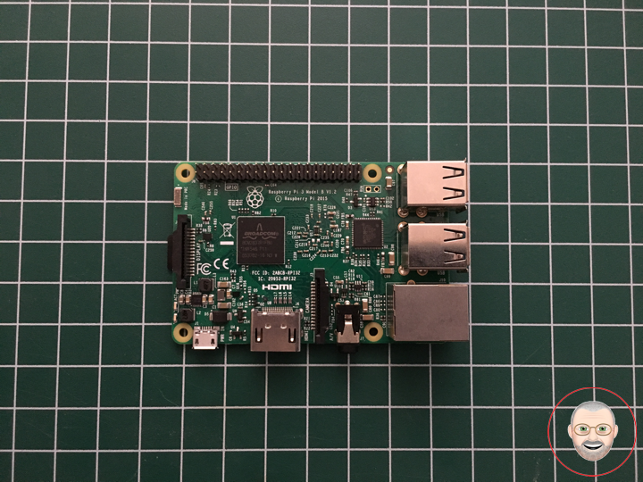
1 x Raspberry Pi 3 – Model B
1 x MicroSD 16 GB
1 x 5V 2A Switching Power Supply
Don Luc
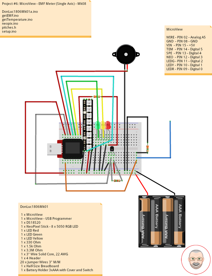
Project #6: MicroView – EMF Meter (Single Axis) – Mk08
Electromagnetic Field
An electromagnetic field (also EMF or EM field) is a physical field produced by electrically charged objects. It affects the behavior of charged objects in the vicinity of the field. The electromagnetic field extends indefinitely throughout space and describes the electromagnetic interaction. It is one of the four fundamental forces of nature (the others are gravitation, weak interaction and strong interaction).
The field can be viewed as the combination of an electric field and a magnetic field. The electric field is produced by stationary charges, and the magnetic field by moving charges (currents); these two are often described as the sources of the field. The way in which charges and currents interact with the electromagnetic field is described by Maxwell’s equations and the Lorentz force law. The force created by the electric field is much stronger than the force created by the magnetic field.
From a classical perspective in the history of electromagnetism, the electromagnetic field can be regarded as a smooth, continuous field, propagated in a wavelike manner; whereas from the perspective of quantum field theory, the field is seen as quantized, being composed of individual particles.
EMF Measurement
EMF measurements are measurements of ambient (surrounding) electromagnetic fields that are performed using particular sensors or probes, such as EMF meters. These probes can be generally considered as antennas although with different characteristics. In fact probes should not perturb the electromagnetic field and must prevent coupling and reflection as much as possible in order to obtain precise results. There are two main types of EMF measurements:
* Broadband measurements performed using a broadband probe, that is a device which senses any signal across a wide range of frequencies and is usually made with three independent diode detectors;
* Frequency selective measurements in which the measurement system consists of a field antenna and a frequency selective receiver or spectrum analyzer allowing to monitor the frequency range of interest.
EMF probes may respond to fields only on one axis, or may be tri-axial, showing components of the field in three directions at once. Amplified, active, probes can improve measurement precision and sensitivity but their active components may limit their speed of response.
EMF Meters
An EMF meter is a scientific instrument for measuring electromagnetic fields (abbreviated as EMF). Most meters measure the electromagnetic radiation flux density (DC fields) or the change in an electromagnetic field over time (AC fields), essentially the same as a radio antenna, but with quite different detection characteristics.
The two largest categories are single axis and tri-axis. Single axis meters are cheaper than tri-axis meters, but take longer to complete a survey because the meter only measures one dimension of the field. Single axis instruments have to be tilted and turned on all three axes to obtain a full measurement. A tri-axis meter measures all three axes simultaneously, but these models tend to be more expensive.
Electromagnetic fields can be generated by AC or DC currents. An EMF meter can measure AC electromagnetic fields, which are usually emitted from man-made sources such as electrical wiring, while gaussmeters or magnetometers measure DC fields, which occur naturally in Earth’s geomagnetic field and are emitted from other sources where direct current is present.
EMF Meter (Single Axis)
1 x MicroView
1 x MicroView – USB Programmer
1 x DS18S20
1 x NeoPixel Stick – 8 x 5050 RGB LED
1 x Speaker
1 x LED Red
1 x LED Green
1 x LED Yellow
1 x 330 Ohm
1 x 1.5k Ohm
1 x 3.3M Ohm
1 x 3″ Wire Solid Core, 22 AWG
1 x 4 Header
20 x Jumper Wires 3″ M/M
1 x Half-Size Breadboard
1 x Battery Holder 3xAAA with Cover and Switch
3 x Battery AAA
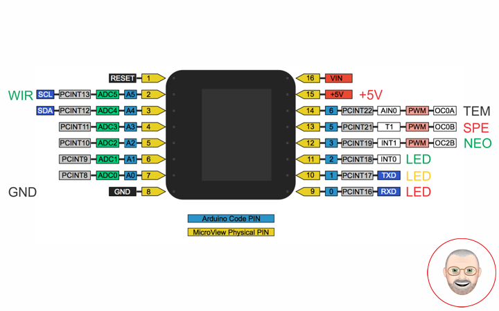
MicroView
WIRE – PIN 02 – Analog A5
GND – PIN 08 – GND
VIN – PIN 15 – +5V
TEM – PIN 14 – Digital 5
SPE – PIN 13 – Digital 4
NEO – PIN 12 – Digital 3
LEDG – PIN 11 – Digital 2
LEDY – PIN 10 – Digital 1
LEDR – PIN 09 – Digital 0
DonLuc1806Mk01
DonLuc1806Mk01a.ino
// ***** Don Luc *****
// Software Version Information
// Project #6: MicroView - EMF Meter (Single Axis) - Mk08
// 6.1
// DonLuc1806Mk01 6-1
// MicroView
// EMF Meter (Single Axis)

// include the library code:
#include <MicroView.h>
#include <Adafruit_NeoPixel.h>
// Pitches
#include "pitches.h"
#include <OneWire.h>

// EMF Meter (Single Axis)
#define NUMREADINGS 15                    // Raise this number to increase data smoothing
int senseLimit = 15;                      // Raise this number to decrease sensitivity (up to 1023 max)
int val = 0;                              // Val
int iEMF = A5;                            // EMF Meter
int readings[ NUMREADINGS ];              // Readings from the analog input
int index = 0;                            // Index of the current reading
int total = 0;                            // Running total
int average = 0;                          // Final average of the probe reading
// NeoPixels
#define PIN 3                             // On digital pin 3
#define NUMPIXELS 8                       // NeoPixels NUMPIXELS = 8
Adafruit_NeoPixel pixels = Adafruit_NeoPixel(NUMPIXELS, PIN, NEO_GRB + NEO_KHZ800);
int red = 0;                              // Red
int green = 0;                            // Green
int blue = 0;                             // Blue
int iNeo = 0;                             // Neopix
int iBri = 0;                             // Neopix Brightness
// LED
int ledR = 0;                             // LED Red
int ledG = 1;                             // LED Green
int ledY = 2;                             // LED Yellow
// 8-ohm speaker
#define tonePIN 5                         // On digital pin 5
// Temperature chip i/o
int DS18S20_Pin = 6;                      // DS18S20 Signal pin on digital 6
OneWire ds(DS18S20_Pin);                  // On digital pin 6
float temperature = 0;                    // Temperature

void loop() {

  // EMF Meter (Single Axis)
  isEMF();

  delay(250);

  uView.clear(PAGE);  // Erase the memory buffer, the OLED will be cleared

}
getEMF.ino
// EMF Meter (Single Axis)
void isEMF(){

  // LEDs - Low
  for(int z=0; z<NUMPIXELS; z++){
     // Black
     red = 0;                                 // Red
     green = 0;                               // Green
     blue = 0;                                // Blue
     iNeo = z;                                // Neopix
     iBri = 0;                                // Neopix Brightness
     neopix();
  }
  digitalWrite(ledG, LOW);                    // Turn that LED off
  digitalWrite(ledY, LOW);                    // Turn that LED off
  noTone(tonePIN);                            // noTone

  // Probe
  val = analogRead( iEMF );                    // Take a reading from the probe

  if( val >= 1 ){                              // If the reading isn't zero, proceed

    val = constrain( val, 1, senseLimit );     // Turn any reading higher than the senseLimit value into the senseLimit value
    val = map( val, 1, senseLimit, 1, 1023 );  // Remap the constrained value within a 1 to 1023 range

    total -= readings[ index ];                // Subtract the last reading
    readings[ index ] = val;                   // Read from the sensor
    total += readings[ index ];                // Add the reading to the total
    index = ( index + 1 );                     // Advance to the next index

    if ( index >= NUMREADINGS ) {              // If we're at the end of the array...
      index = 0;                               // ...wrap around to the beginning
    }

    average = total / NUMREADINGS;             // Calculate the average

    if (average < 50) {                        // If the average is less 50 ...
      digitalWrite(ledG, HIGH);                // turn that LED On
      tone(tonePIN, NOTE_C3);                  // Tone
    }
    else{                                      // and if it's not ...
      digitalWrite(ledG, LOW);                 // turn that LED off
      noTone(tonePIN);                         // noTone
    }

    if (average > 50){                         // If the average is over 50 ...
      // Green
      red = 0;                                 // Red
      green = 255;                             // Green
      blue = 0;                                // Blue
      iNeo = 0;                                // Neopix
      iBri = 100;                              // Neopix Brightness
      neopix();
      tone(tonePIN, NOTE_C4);                  // Tone
    }
    else{                                      // and if it's not ...
      // Black
      red = 0;                                 // Red
      green = 0;                               // Green
      blue = 0;                                // Blue
      iNeo = 0;                                // Neopix
      iBri = 0;                                // Neopix Brightness
      neopix();
      noTone(tonePIN);                         // noTone
    }

    if (average > 250){                        // and so on ...
      // Green
      red = 0;                                 // Red
      green = 255;                             // Green
      blue = 0;                                // Blue
      iNeo = 1;                                // Neopix
      iBri = 100;                              // Neopix Brightness
      neopix();
      tone(tonePIN, NOTE_D4);                  // Tone
    }
    else{
      // Black
      red = 0;                                 // Red
      green = 0;                               // Green
      blue = 0;                                // Blue
      iNeo = 1;                                // Neopix
      iBri = 0;                                // Neopix Brightness
      neopix();
      noTone(tonePIN);                         // noTone
    }

    if (average > 350){
      // Green
      red = 0;                                 // Red
      green = 255;                             // Green
      blue = 0;                                // Blue
      iNeo = 2;                                // Neopix
      iBri = 100;                              // Neopix Brightness
      neopix();
      tone(tonePIN, NOTE_E4);                  // Tone
    }
    else{
      // Black
      red = 0;                                 // Red
      green = 0;                               // Green
      blue = 0;                                // Blue
      iNeo = 1;                                // Neopix
      iBri = 0;                                // Neopix Brightness
      neopix();
      noTone(tonePIN);                         // noTone
    }


    if (average > 500){
      // Yellow
      red = 255;                               // Red
      green = 255;                             // Green
      blue = 0;                                // Blue
      iNeo = 3;                                // Neopix
      iBri = 100;                              // Neopix Brightness
      neopix();
      tone(tonePIN, NOTE_F4);                  // Tone
    }
    else{
      // Black
      red = 0;                                 // Red
      green = 0;                               // Green
      blue = 0;                                // Blue
      iNeo = 3;                                // Neopix
      iBri = 0;                                // Neopix Brightness
      neopix();
      noTone(tonePIN);                         // noTone
    }

    if (average > 650){
      // Yellow
      red = 255;                               // Red
      green = 255;                             // Green
      blue = 0;                                // Blue
      iNeo = 4;                                // Neopix
      iBri = 100;                              // Neopix Brightness
      neopix();
      tone(tonePIN, NOTE_G4);                  // Tone
    }
    else{
      // Black
      red = 0;                                 // Red
      green = 0;                               // Green
      blue = 0;                                // Blue
      iNeo = 4;                                // Neopix
      iBri = 0;                                // Neopix Brightness
      neopix();
      noTone(tonePIN);                         // noTone
    }

    if (average > 750){
      // Yellow
      red = 255;                               // Red
      green = 255;                             // Green
      blue = 0;                                // Blue
      iNeo = 5;                                // Neopix
      iBri = 100;                              // Neopix Brightness
      neopix();
      tone(tonePIN, NOTE_A4);                  // Tone
    }
    else{
      // Black
      red = 0;                                 // Red
      green = 0;                               // Green
      blue = 0;                                // Blue
      iNeo = 5;                                // Neopix
      iBri = 0;                                // Neopix Brightness
      neopix();
      noTone(tonePIN);                         // noTone
    }

    if (average > 850){
      // Red
      red = 255;                               // Red
      green = 0;                               // Green
      blue = 0;                                // Blue
      iNeo = 6;                                // Neopix
      iBri = 100;                              // Neopix Brightness
      neopix();
      tone(tonePIN, NOTE_B4);                  // Tone
    }
    else{
      // Black
      red = 0;                                 // Red
      green = 0;                               // Green
      blue = 0;                                // Blue
      iNeo = 6;                                // Neopix
      iBri = 0;                                // Neopix Brightness
      neopix();
      noTone(tonePIN);                         // noTone
    }

    if (average > 950){
      // Red
      red = 255;                               // Red
      green = 0;                               // Green
      blue = 0;                                // Blue
      iNeo = 7;                                // Neopix
      iBri = 100;                              // Neopix Brightness
      neopix();
      tone(tonePIN, NOTE_C5);                  // Tone
    }
    else{
      // Black
      red = 0;                                 // Red
      green = 0;                               // Green
      blue = 0;                                // Blue
      iNeo = 7;                                // Neopix
      iBri = 0;                                // Neopix Brightness
      neopix();
      noTone(tonePIN);                         // noTone
    }

  }
  else
  {

    digitalWrite(ledY, HIGH);                  // turn that LED On
    noTone(tonePIN);                           // noTone

  }

  uView.setFontType(0);  // Set font type 0: Numbers and letters. 10 characters per line (6 lines)

  uView.setCursor(0,10); // EMF Meter
  uView.print( "EMF: " );
  uView.print( average );

  // Temperature chip i/o
  isTe();

  uView.display();       // Display

}
getTemperature.ino
// Temperature chip i/o
void isTe() {

  // Temperature chip i/o
  temperature = getTemp();

  uView.setCursor(0,30);
  uView.print(temperature);
  uView.print(" *C");

}

float getTemp() {

  // Returns the temperature from one DS18S20 in DEG Celsius
  byte data[12];
  byte addr[8];

  if ( !ds.search(addr)) {
      // No more sensors on chain, reset search
      ds.reset_search();
      return -1001;
  }

  if ( OneWire::crc8( addr, 7) != addr[7]) {
      return -1002;
  }

  if ( addr[0] != 0x10 && addr[0] != 0x28) {
      return -1003;
  }

  ds.reset();
  ds.select(addr);
  ds.write(0x44,1);                           // Start conversion, with parasite power on at the end

  byte present = ds.reset();
  ds.select(addr);
  ds.write(0xBE);                             // Read Scratchpad


  for (int i = 0; i < 9; i++) {               // we need 9 bytes
    data[i] = ds.read();
  }

  ds.reset_search();

  byte MSB = data[1];
  byte LSB = data[0];

  float tempRead = ((MSB << 8) | LSB);        // Using two's compliment
  float TemperatureSum = tempRead / 16;

  return TemperatureSum;

}
neopix.ino
void neopix() {

    // Brightness
    pixels.setBrightness( iBri );
    // Pixels.Color takes RGB values, from 0,0,0 up to 255,255,255
    pixels.setPixelColor( iNeo, pixels.Color(red,green,blue) );
    // This sends the updated pixel color to the hardware
    pixels.show();
    // Delay for a period of time (in milliseconds)
    delay(50);

}
pitches.h
/*************************************************
 * Public Constants
 *************************************************/

// Note
#define NOTE_B0  31
#define NOTE_C1  33
#define NOTE_CS1 35
#define NOTE_D1  37
#define NOTE_DS1 39
#define NOTE_E1  41
#define NOTE_F1  44
#define NOTE_FS1 46
#define NOTE_G1  49
#define NOTE_GS1 52
#define NOTE_A1  55
#define NOTE_AS1 58
#define NOTE_B1  62
#define NOTE_C2  65
#define NOTE_CS2 69
#define NOTE_D2  73
#define NOTE_DS2 78
#define NOTE_E2  82
#define NOTE_F2  87
#define NOTE_FS2 93
#define NOTE_G2  98
#define NOTE_GS2 104
#define NOTE_A2  110
#define NOTE_AS2 117
#define NOTE_B2  123
#define NOTE_C3  131
#define NOTE_CS3 139
#define NOTE_D3  147
#define NOTE_DS3 156
#define NOTE_E3  165
#define NOTE_F3  175
#define NOTE_FS3 185
#define NOTE_G3  196
#define NOTE_GS3 208
#define NOTE_A3  220
#define NOTE_AS3 233
#define NOTE_B3  247
#define NOTE_C4  262
#define NOTE_CS4 277
#define NOTE_D4  294
#define NOTE_DS4 311
#define NOTE_E4  330
#define NOTE_F4  349
#define NOTE_FS4 370
#define NOTE_G4  392
#define NOTE_GS4 415
#define NOTE_A4  440
#define NOTE_AS4 466
#define NOTE_B4  494
#define NOTE_C5  523
#define NOTE_CS5 554
#define NOTE_D5  587
#define NOTE_DS5 622
#define NOTE_E5  659
#define NOTE_F5  698
#define NOTE_FS5 740
#define NOTE_G5  784
#define NOTE_GS5 831
#define NOTE_A5  880
#define NOTE_AS5 932
#define NOTE_B5  988
#define NOTE_C6  1047
#define NOTE_CS6 1109
#define NOTE_D6  1175
#define NOTE_DS6 1245
#define NOTE_E6  1319
#define NOTE_F6  1397
#define NOTE_FS6 1480
#define NOTE_G6  1568
#define NOTE_GS6 1661
#define NOTE_A6  1760
#define NOTE_AS6 1865
#define NOTE_B6  1976
#define NOTE_C7  2093
#define NOTE_CS7 2217
#define NOTE_D7  2349
#define NOTE_DS7 2489
#define NOTE_E7  2637
#define NOTE_F7  2794
#define NOTE_FS7 2960
#define NOTE_G7  3136
#define NOTE_GS7 3322
#define NOTE_A7  3520
#define NOTE_AS7 3729
#define NOTE_B7  3951
#define NOTE_C8  4186
#define NOTE_CS8 4435
#define NOTE_D8  4699
#define NOTE_DS8 4978
setup.ino
void setup() {

  uView.begin();           // Begin of MicroView
  uView.clear(ALL);        // Erase hardware memory inside the OLED controller
  uView.display();         // Display the content in the buffer memory, by default it is the MicroView logo

  delay(1000);

  uView.clear(PAGE);       // Erase the memory buffer, the OLED will be cleared.

  uView.setFontType(1);    // Set font type 1: Numbers and letters. 7 characters per line (3 lines)
  uView.setCursor(0,20);
  uView.print("Don Luc");  // Don Luc
  uView.display();         // Display

  delay(5000);

  uView.clear(PAGE);       // Erase the memory buffer, the OLED will be cleared.

  uView.setFontType(1);    // Set font type 1: Numbers and letters. 7 characters per line (3 lines)
  uView.setCursor(0,20);
  uView.print("EMF Met");  // EMF Meter (Single Axis)
  uView.display();         // Display

  delay(5000);

  uView.clear(PAGE);       // Erase the memory buffer, the OLED will be cleared

  // NeoPixels
  pixels.begin();          // This initializes the NeoPixel library
  // EMF Meter (Single Axis)
  pinMode( iEMF, OUTPUT ); // EMF Meter
  for (int i = 0; i < NUMREADINGS; i++){
    readings[ i ] = 0;     // Initialize all the readings to 0
  }
  // LED
  pinMode( ledR, OUTPUT ); // LED Red
  pinMode( ledG, OUTPUT ); // LED Green
  pinMode( ledY, OUTPUT ); // LED Yellow
  // LED Red - High
  digitalWrite( ledR, HIGH);

}
Don Luc
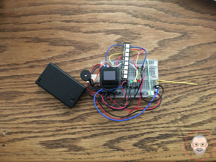
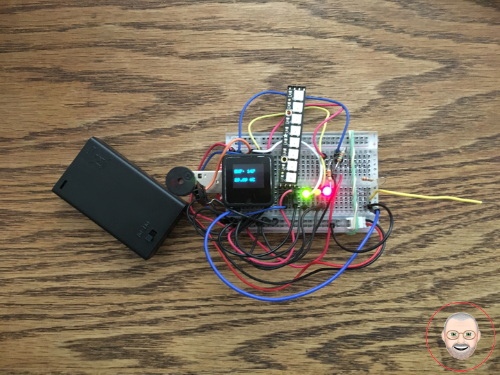
Project #7: RGB LCD Shield – PIR Motion Sensor – Mk03
PIR Motion Sensor
This is a simple to use motion sensor. Power it up and wait 1-2 seconds for the sensor to get a snapshot of the still room. If anything moves after that period, the ‘alarm’ pin will go low.
This unit works great from 5 to 12V (datasheet shows 12V). You can also install a jumper wire past the 5V regulator on board to make this unit work at 3.3V. Sensor uses 1.6mA@3.3V.
The alarm pin is an open collector meaning you will need a pull up resistor on the alarm pin. The open drain setup allows multiple motion sensors to be connected on a single input pin. If any of the motion sensors go off, the input pin will be pulled low.
We’ve finally updated the connector! Gone is the old “odd” connector, now you will find a common 3-pin JST! This makes the PIR Sensor much more accessible for whatever your project may need. Red = Power, White = Ground, and Black = Alarm.
Buzzer
This is a small 12mm round speaker that operates around the audible 2kHz range. You can use these speakers to create simple music or user interfaces.
This is not a true piezoelectric speaker but behaves similarly. Instead of a piezoelectric crystal that vibrates with an electric current, this tiny speaker uses an electromagnet to drive a thin metal sheet. That means you need to use some form of alternating current to get sound. The good news is that this speaker is tuned to respond best with a square wave (e.g. from a microcontroller).
LED
LED Yellow
LED Green
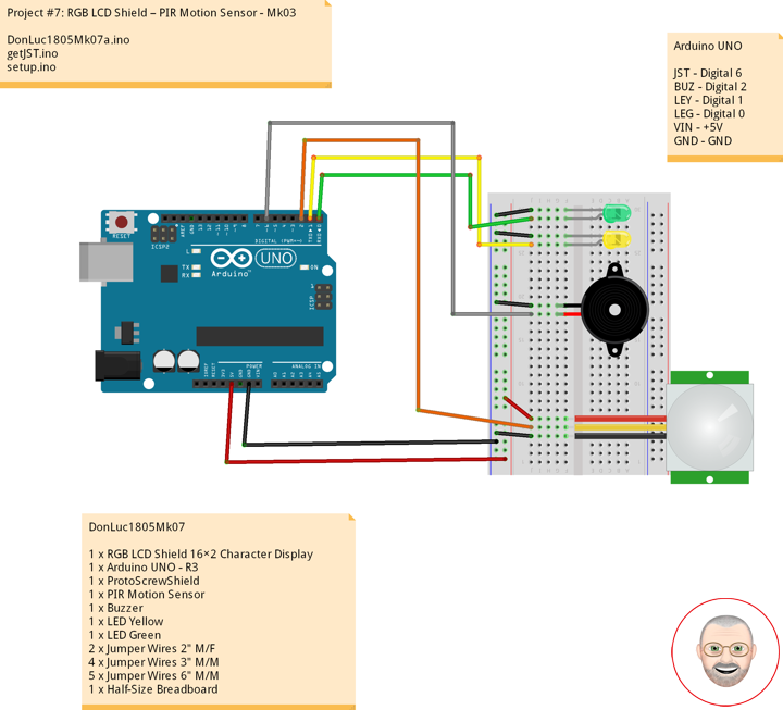
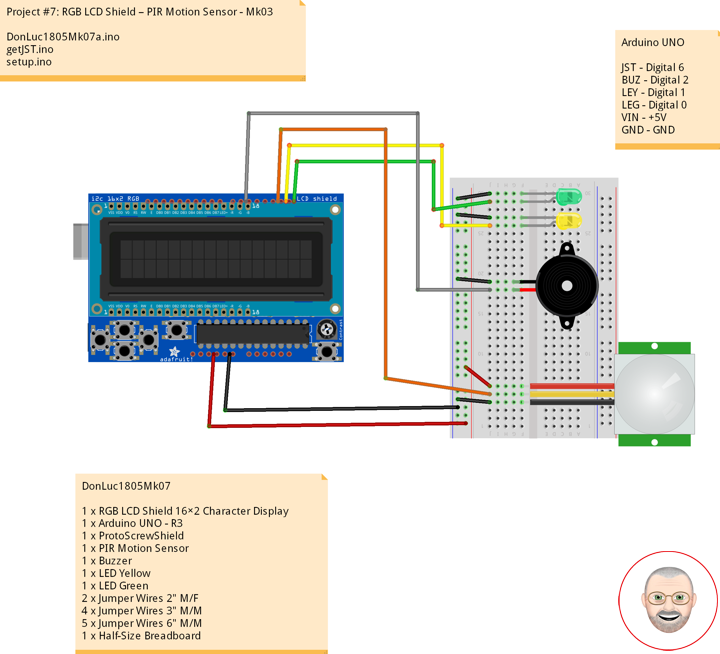
DonLuc1805Mk07
1 x RGB LCD Shield 16×2 Character Display
1 x Arduino UNO – R3
1 x ProtoScrewShield
1 x PIR Motion Sensor
1 x Buzzer
1 x LED Yellow
1 x LED Green
2 x Jumper Wires 2″ M/F
4 x Jumper Wires 3″ M/M
5 x Jumper Wires 6″ M/M
1 x Half-Size Breadboard
Arduino UNO
JST – Digital 6
BUZ – Digital 2
LEY – Digital 1
LEG – Digital 0
VIN – +5V
GND – GND
DonLuc1805Mk07a.ino
// ***** Don Luc *****
// Software Version Information
// Project #7: RGB LCD Shield – PIR Motion Sensor - Mk03
// 5-3.01
// DonLuc1804Mk07 5-3.01
// RGB LCD Shield
// PIR Motion Sensor (JST}

// include the library code:
#include <Adafruit_MCP23017.h>
#include <Adafruit_RGBLCDShield.h>

Adafruit_RGBLCDShield RGBLCDShield = Adafruit_RGBLCDShield();
#define GREEN 0x2

// PIR Motion Sensor (JST}
const int buz = 6;          // Buzzer
const int MOTION_PIN = 2;   // Pin connected to motion detector
const int LED_Yellow = 1;   // LED Yellow
const int LED_Green = 0;    // LED Green

void loop() {

  // PIR Motion Sensor (JST}
  isJST();

  delay(1000);

  // Clear
  RGBLCDShield.clear();

}
getJST.ino
void isJST(){
int proximity = digitalRead(MOTION_PIN); // PIR Motion Sensor
if (proximity == LOW) // If the sensor's output goes low, motion is detected
{
// Motion Detected
digitalWrite(buz, HIGH); // Buzzer High
digitalWrite(LED_Yellow, HIGH); // LED Yellow High
digitalWrite(LED_Green, LOW); // LED Green Low
// Display
// Set the cursor to column 0, line 0
RGBLCDShield.setCursor(0,0);
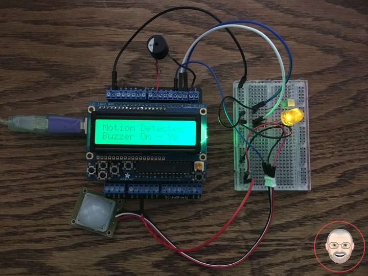
RGBLCDShield.print("Motion Detected!"); // Motion Detected!
// Set the cursor to column 0, line 1
RGBLCDShield.setCursor(0, 1);
RGBLCDShield.print("Buzzer On - Yel"); // Buzzer On
}
else
{
// Motion Off
digitalWrite(buz, LOW); // Buzzer Low
digitalWrite(LED_Yellow, LOW); // LED Yellow Low
digitalWrite(LED_Green, HIGH); // LED Green High
// Display
// Set the cursor to column 0, line 0
RGBLCDShield.setCursor(0,0);
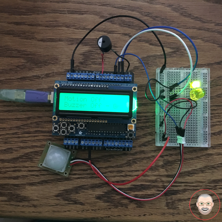
RGBLCDShield.print("Motion Off!"); // Motion Off!
// Set the cursor to column 0, line 1
RGBLCDShield.setCursor(0, 1);
RGBLCDShield.print("Buzzer Off - Gr"); // "Buzzer Off
}
}
setup.ino
void setup() {

  // set up the LCD's number of columns and rows:
  RGBLCDShield.begin(16, 2);
  RGBLCDShield.setBacklight(GREEN);

  // Display
  // Set the cursor to column 0, line 0
  RGBLCDShield.setCursor(0,0);
  RGBLCDShield.print("Don Luc");         // Don luc
  // Set the cursor to column 0, line 1
  RGBLCDShield.setCursor(0, 1);
  RGBLCDShield.print("Motion Sensor");   // Motion Sensor

  delay(5000);

  // Clear
  RGBLCDShield.clear();

  // PIR Motion Sensor (JST}
  pinMode(buz, OUTPUT);                // Buzzer
  pinMode(MOTION_PIN, INPUT_PULLUP);   // PIR Motion Sensor
  pinMode(LED_Yellow, OUTPUT);         // LED Yellow
  pinMode(LED_Green, OUTPUT);          // LED Green

}
Don Luc
Project #6: MicroView – RHT03 Sensor – Mk07
RHT03 Humidity and Temperature Sensor
The RHT03 (also known by DHT-22) is a low cost humidity and temperature sensor with a single wire digital interface. The sensor is calibrated and doesn’t require extra components so you can get right to measuring relative humidity and temperature.
Features
* 3.3-6V Input
* 1-1.5mA measuring current
* 40-50 uA standby current
* Humidity from 0-100% RH
* -40 – 80 degrees C temperature range
* +-2% RH accuracy
* +-0.5 degrees C
Technical Specification
Model: RHT03
Power supply: 3.3-6V DC
Output signal: Digital signal via MaxDetect 1-wire bus
Sensing element: Polymer humidity capacitor
Operating range: Humidity 0-100%RH; Temperature -40~80C
Accuracy: humidity +-2%RH(Max +-5%RH); Temperature +-0.5C
Resolution or sensitivity: Humidity 0.1%RH; Temperature 0.1C
Repeatability: Humidity +-1%RH; Temperature +-0.2C – Humidity hysteresis – +-0.3%RH
Long-term Stability: +-0.5%RH/year
Interchangeability: Fully interchangeable
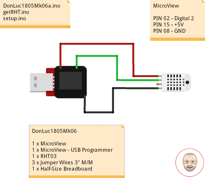
DonLuc1805Mk06
1 x MicroView
1 x MicroView – USB Programmer
1 x RHT03
3 x Jumper Wires 3″ M/M
1 x Half-Size Breadboard
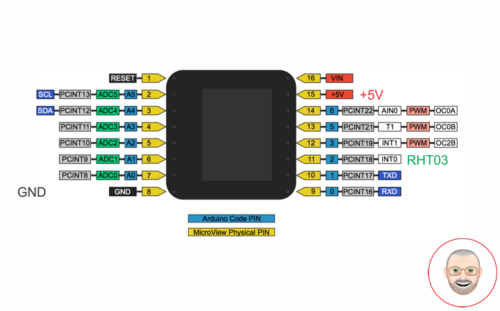
MicroView
RHT – PIN 11 – Digital 2
VIN – PIN 15 – +5V
GND – PIN 08 – GND
DonLuc1805Mk06a.ino
// ***** Don Luc *****
// Software Version Information
// 7.01
// DonLuc1804Mk07 7.01
// MicroView
// RHT03 Humidity and Temperature Sensor

// include the library code:
#include <MicroView.h>
#include <SparkFun_RHT03.h>

// RHT Humidity and Temperature Sensor
const int RHT03_DATA_PIN = 2;           // RHT03 data pin Digital 2
RHT03 rht;                              // This creates a RTH03 object, which we'll use to interact with the sensor

void loop() {

  // RHT03 Humidity and Temperature Sensor
  isRHT03();

  delay(1000);

  uView.clear(PAGE);  // Erase the memory buffer, the OLED will be cleared

}
getRHT.ino
// RHT03 Humidity and Temperature Sensor
void isRHT03(){
// Call rht.update() to get new humidity and temperature values from the sensor.
int updateRet = rht.update();
// The humidity(), tempC(), and tempF() functions can be called -- after
// a successful update() -- to get the last humidity and temperature
// value
float latestHumidity = rht.humidity();
float latestTempC = rht.tempC();
float latestTempF = rht.tempF();
uView.setFontType(0); // Set font type 0: Numbers and letters. 10 characters per line (6 lines)
uView.setCursor(0,10); // Humidity
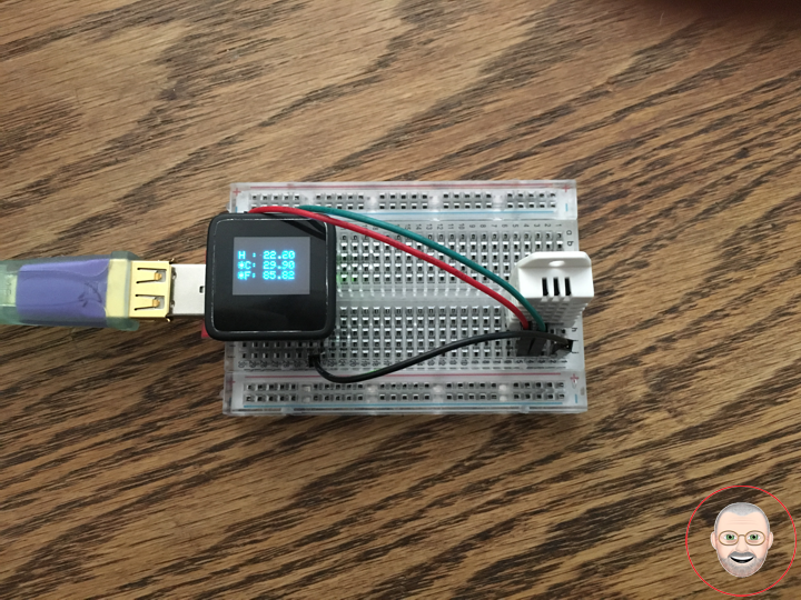
uView.print( "H : " );
uView.print( latestHumidity );
uView.setCursor(0,20); // Temperature *C
uView.print( "*C: " );
uView.print( latestTempC );
uView.setCursor(0,30); // "Temperature *F
uView.print( "*F: " );
uView.print( latestTempF );
uView.display(); // Display
}
setup.ino
void setup() {

  uView.begin();           // Begin of MicroView
  uView.clear(ALL);        // Erase hardware memory inside the OLED controller
  uView.display();         // Display the content in the buffer memory, by default it is the MicroView logo

  delay(1000);

  uView.clear(PAGE);       // Erase the memory buffer, the OLED will be cleared.

  uView.setFontType(1);    // Set font type 1: Numbers and letters. 7 characters per line (3 lines)
  uView.setCursor(0,20);
  uView.print("Don Luc");  // Don Luc
  uView.display();         // Display

  delay(5000);

  uView.clear(PAGE);       // Erase the memory buffer, the OLED will be cleared.

  uView.setFontType(1);    // Set font type 1: Numbers and letters. 7 characters per line (3 lines)
  uView.setCursor(0,20);
  uView.print("RHT03");    // RHT03
  uView.display();         // Display

  delay(5000);

  uView.clear(PAGE);       // Erase the memory buffer, the OLED will be cleared

  // RHT03 Humidity and Temperature Sensor
  // Call rht.begin() to initialize the sensor and our data pin
  rht.begin(RHT03_DATA_PIN);

}
Don Luc
Project #6: MicroView – Accelerometer ADXL335 – Mk06
Accelerometer
An accelerometer is a device that measures proper acceleration. Proper acceleration, being the acceleration (or rate of change of velocity) of a body in its own instantaneous rest frame, is not the same as coordinate acceleration, being the acceleration in a fixed coordinate system. For example, an accelerometer at rest on the surface of the Earth will measure an acceleration due to Earth’s gravity, straight upwards (by definition) of g = 9.81 m/s2. By contrast, accelerometers in free fall (falling toward the center of the Earth at a rate of about 9.81 m/s2) will measure zero.
Triple Axis Accelerometer Breakout – ADXL335
Breakout board for the 3 axis ADXL335 from Analog Devices. This is the latest in a long, proven line of analog sensors – the holy grail of accelerometers. The ADXL335 is a triple axis MEMS accelerometer with extremely low noise and power consumption – only 320uA! The sensor has a full sensing range of +/-3g. There is no on-board regulation, provided power should be between 1.8 and 3.6VDC. Board comes fully assembled and tested with external components installed. The included 0.1uF capacitors set the bandwidth of each axis to 50Hz.
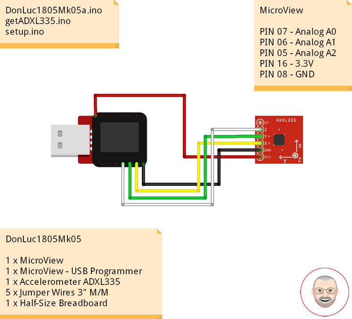
DonLuc1805Mk05
1 x MicroView
1 x MicroView – USB Programmer
1 x Accelerometer ADXL335
5 x Jumper Wires 3″ M/M
1 x Half-Size Breadboard
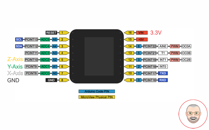
MicroView
Z-Axis – PIN 07 – Analog A0
Y-Axis – PIN 06 – Analog A1
X-Axis – PIN 05 – Analog A2
VIN – PIN 16 – 3.3V
GND – PIN 08 – GND
DonLuc1805Mk05a.ino
// ***** Don Luc *****
// Software Version Information
// 6.01
// DonLuc1804Mk06 6.01
// MicroView
// Accelerometer ADXL335

// include the library code:
#include <MicroView.h>
#include <ADXL335.h>

// Accelerometer ADXL335
const int pin_x = A0;     // X-Axis
const int pin_y = A1;     // Y-Axis
const int pin_z = A2;     // Z-Axis
const int vin = 16;       // 3.3V
const int gnd = 8;        // GND

ADXL335 accel(pin_x, pin_y, pin_z, vin);

void loop() {

  // Accelerometer ADXL335
  isADXL335();

  delay(500);

  uView.clear(PAGE);  // Erase the memory buffer, the OLED will be cleared

}
getADXL335.ino
// Accelerometer ADXL335
void isADXL335(){
// This is required to update the values
accel.update();
float rho;
float phi;
float theta;
rho = accel.getRho();
phi = accel.getPhi();
theta = accel.getTheta();
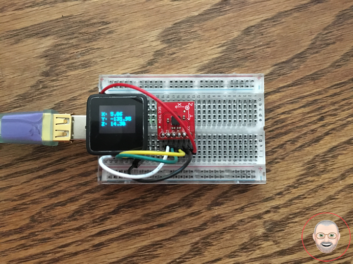
uView.setFontType(0); // Set font type 0: Numbers and letters. 10 characters per line (6 lines)
uView.setCursor(0,10); // X-Axis
uView.print( "X: " );
uView.print( rho );
uView.setCursor(0,20); // Y-Axis
uView.print( "Y: " );
uView.print( phi );
uView.setCursor(0,30); // Z-Axis
uView.print( "Z: " );
uView.print( theta );
uView.display(); // Display
}
setup.ino
void setup() {

  uView.begin();           // Begin of MicroView
  uView.clear(ALL);        // Erase hardware memory inside the OLED controller
  uView.display();         // Display the content in the buffer memory, by default it is the MicroView logo

  delay(1000);

  uView.clear(PAGE);       // Erase the memory buffer, the OLED will be cleared.

  uView.setFontType(1);    // Set font type 1: Numbers and letters. 7 characters per line (3 lines)
  uView.setCursor(0,20);
  uView.print("Don Luc");  // Don Luc
  uView.display();         // Display

  delay(5000);

  uView.clear(PAGE);       // Erase the memory buffer, the OLED will be cleared.

  uView.setFontType(1);    // Set font type 1: Numbers and letters. 7 characters per line (3 lines)
  uView.setCursor(0,20);
  uView.print("ADXL335");  // ADXL335
  uView.display();         // Display

  delay(5000);

  uView.clear(PAGE);       // Erase the memory buffer, the OLED will be cleared

  // Accelerometer ADXL335
  pinMode(gnd, OUTPUT);    // GND
  pinMode(vin, OUTPUT);    // 3.3V
  digitalWrite(gnd, LOW);
  digitalWrite(vin, HIGH);

}
Don Luc
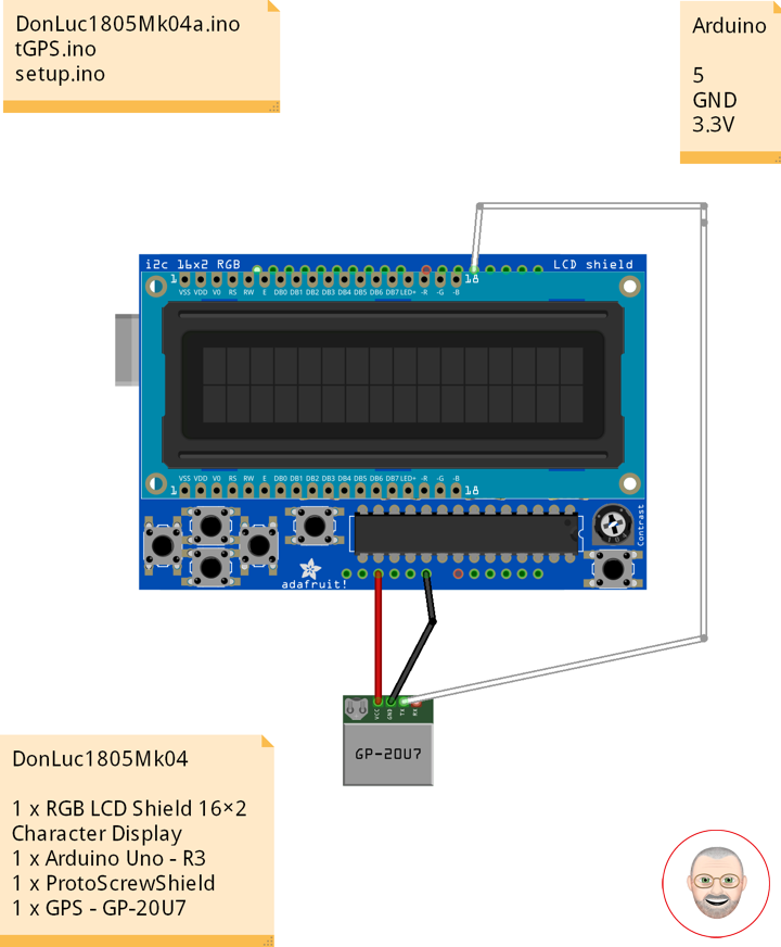
Project #7: RGB LCD Shield – GPS Receiver – Mk02
GPS Receiver
Global Positioning System
The Global Positioning System (GPS), originally Navstar GPS, is a satellite-based radionavigation system owned by the United States government and operated by the United States Air Force. It is a global navigation satellite system that provides geolocation and time information to a GPS receiver anywhere on or near the Earth where there is an unobstructed line of sight to four or more GPS satellites. Obstacles such as mountains and buildings block the relatively weak GPS signals.
The GPS does not require the user to transmit any data, and it operates independently of any telephonic or internet reception, though these technologies can enhance the usefulness of the GPS positioning information. The GPS provides critical positioning capabilities to military, civil, and commercial users around the world. The United States government created the system, maintains it, and makes it freely accessible to anyone with a GPS receiver.
DonLuc1805Mk04
1 x RGB LCD Shield 16×2 Character Display
1 x Arduino UNO – R3
1 x ProtoScrewShield
1 x GPS – GP-20U7
Arduino UNO
Digital 5
GND
3.3V
DonLuc1805Mk04a.ino
// ***** Don Luc *****
// Software Version Information
// 5-4.01
// DonLuc1805Mk04 5-4.01
// RGB LCD Shield
// GPS
// include the library code:
#include <Adafruit_MCP23017.h>
#include <Adafruit_RGBLCDShield.h>
#include <TinyGPS.h>
#include <SoftwareSerial.h>
Adafruit_RGBLCDShield RGBLCDShield = Adafruit_RGBLCDShield();
#define GREEN 0x2
// GPS
#define gpsRXPIN 5
#define gpsTXPIN 4 //this one is unused and doesnt have a conection
SoftwareSerial tGPS(gpsRXPIN, gpsTXPIN);
TinyGPS gps;
// Global variables and functions are declared here, this allows them to be called anywhere
// within the code and is helpful for passing data out of functions. Dont get in the habit \
// of using these though because as your code gets longer its easy to lose track of where
// you are changing these variables and can lead to a headach when a problem arises.
float TargetLat;
float TargetLon;
int Status = 0;
// Function headers can be placed here so that functions can be placed below your setup
// and loop function for a more logical flow of information.
void getGPS( float* lat, float* lon, int* Status);
void loop() {
RGBLCDShield.clear();
// Receives NEMA data from GPS receiver and Parses Latitude and longitude data
// returns information using pointers including info on stagnant data
// Here we tell it to listen to the tGPS serial object
// then call the function that will recieve and parse the signal from the GPS reciver
tGPS.listen();
getGPS(&TargetLat, &TargetLon, &Status);
// Print status to console to know if you are getting good data or not.
// No Lock = 0, Old Data(>5 sec old) = 1, Good Data = 2
// set the cursor to column 0, line 0
RGBLCDShield.setCursor(0,0);
RGBLCDShield.print( "Status:" );
RGBLCDShield.print( Status );
delay(2000);
RGBLCDShield.clear();
// set the cursor to column 0, line 0
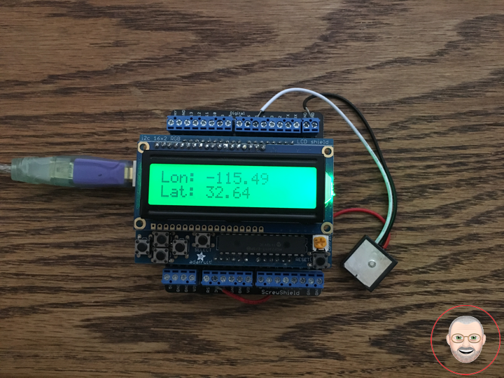
RGBLCDShield.setCursor(0,0);
RGBLCDShield.print( "Lon: " );
RGBLCDShield.print( TargetLon );
// set the cursor to column 0, line 1
RGBLCDShield.setCursor(0, 1);
RGBLCDShield.print( "Lat: " );
RGBLCDShield.print( TargetLat );
delay(5000);
}
tGPS.ino
/* GPS Vector Pointer Target
   This sketch simiulates any system that has a GPS beacon and has the ability to
   broadcast this information for other systems to pick up. This could be a plane/drone
   a car/rover or even a solar panel on a space elevator climber. This recieves updating GPS
   coordinates and from an attached GPS receiver, parses the incoming NEMA data and
   send that information using an Xbee connection to the base station.
*/

void getGPS( float* lat, float* lon, int* Status)
/* This function switches the softserial pin to the one used for GPS then recieves NEMA data from a GPS
   receiver which is passed into a TinyGPS Object and parsed using its internal functions for $GPRMC info. This function uses
   pointers to pass infomation to pass back to parent function which includes Latitude, longitude,( velocity,
   heading) and the status of the GPS signal. Function call where variables can be nammed whatever they want as long as they have &:
   getGPS(&latitude, &longitude, &Status);
*/
{
  // Initilize pin to receive NEMA (have to do it here because we need to switch between
  // software serial pins (if time permits interrupts could be used)

  // define local variables
  float flat;
  float flon;
  unsigned long fix_age;

  //look for serial data from GPS and loop untill the end of NEMA string
  while (tGPS.available())
  {

    int c = tGPS.read();

    if (gps.encode(c));
    {}

  }

  //Pulled parsed data from gps object
  gps.f_get_position(&flat, &flon, &fix_age);
  *lat = flat;
  *lon = flon;

  // check if data is relavent
  if (fix_age == TinyGPS::GPS_INVALID_AGE)
    //No fix detected;
  {
    *Status = 0;
  }

  else if (fix_age > 5000)
    //Warning: possible stale data!;
  {
    *Status = 1;
  }

  else
    //Data is current;
  {
    *Status = 2;
  }

}
setup.ino
void setup() {

  // set up the LCD's number of columns and rows:
  RGBLCDShield.begin(16, 2);

  RGBLCDShield.print("Don Luc");
  RGBLCDShield.setBacklight(GREEN);
   // set the cursor to column 0, line 1
  RGBLCDShield.setCursor(0, 1);
  // print the number of seconds since reset:
  RGBLCDShield.print("GPS - GP-20U7");

  delay(5000);

  // This function is run before the your program begins to loop, here we define the status
  // of pins that are used for inputs and outputs
  pinMode(gpsRXPIN, INPUT);

  // Next communication begins between the three systems along for the baud rate for each
  // some of these can handle a larger baud rate but you need to make sure they match what
  // they are communicating with
  tGPS.begin(9600);
  Serial.begin(9600);

}
Don Luc
Project #6: MicroView – Mk05
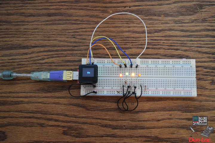
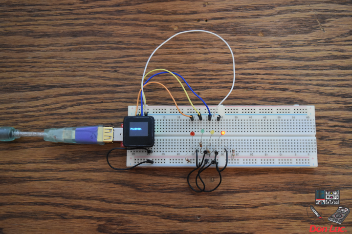

MicroView
Project #6 – Mk05
4 x LED
1 x MicroView
1 x MicroView – USB Programmer
1 X Resistor 620 Ohm
1 X Resistor 5 Ohm
1 X Resistor 250 Ohm
1 X Resistor 200 Ohm
1 X 3mm Low Current Red LED – WP710A10LSRD
1 x 3mm Low Current Yellow LED – WP710A10LYD
1 x 3mm Low Current Green LED – WP710A10LGD
1 x 3mm Low Current Red LED – WP710A10LID
9 x Jumper Wires 3″ M/M
1 x Half-Size Breadboard
08 pin – GND
14 pin – 6
13 pin – 5
12 pin – 3
11 pin – 2
DonLuc1804Mk09a.ino
// ***** Don Luc *****
// Software Version Information
// 5.01
// DonLuc1804Mk06 5.01
// MicroView
// 4 x LED

// include the library code:
#include <MicroView.h>

// 4 x LED
int ledPinR = 2;   // select the pin for the LED Red - WP710A10LSRD
int ledPinY = 3;   // select the pin for the LED Yellow - WP710A10LYD
int ledPinG = 5;   // select the pin for the LED Green - WP710A10LGD
int ledPinR1 = 6;   // select the pin for the LED Red - WP710A10LID

void loop() {

  // 4 x LED
  isLED();

  uView.clear(PAGE);

}
getLED.ino
void isLED(){
digitalWrite(ledPinR, HIGH); // turn the ledPinR on
digitalWrite(ledPinY, HIGH); // turn the ledPinY on
digitalWrite(ledPinG, HIGH); // turn the ledPinG on
digitalWrite(ledPinR1, HIGH); // turn the ledPinR1 on
uView.setFontType(1); // set font type 1: Numbers and letters. 7 characters per line (3 lines)
uView.setCursor(0,20);
uView.print( " On" );
uView.display();
delay(5000);
uView.clear(PAGE);
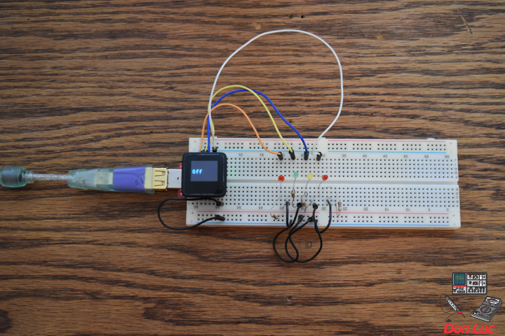
digitalWrite(ledPinR, LOW); // turn the ledPinR off
digitalWrite(ledPinY, LOW); // turn the ledPinY off
digitalWrite(ledPinG, LOW); // turn the ledPinG off
digitalWrite(ledPinR1, LOW); // turn the ledPinR1 off
uView.setCursor(0,20);
uView.print( " Off" );
uView.display();
delay(5000);
uView.clear(PAGE);
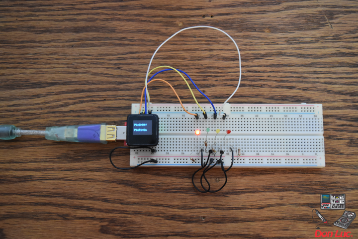
digitalWrite(ledPinR, HIGH); // turn the ledPinR on
uView.setFontType(0); // set font type 0: Numbers and letters. 10 characters per line (6 lines)
uView.setCursor(0,20);
uView.print( "PinR=On" );
uView.display();
delay(3000);
uView.clear(PAGE);
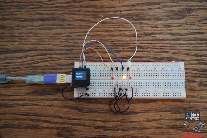
digitalWrite(ledPinR, LOW); // turn the ledPinR off
digitalWrite(ledPinY, HIGH); // turn the ledPinY on
uView.setCursor(0,10);
uView.print( "PinR=Off" );
uView.display();
uView.setCursor(0,30);
uView.print( "PinY=On" );
uView.display();
delay(3000);
uView.clear(PAGE);
digitalWrite(ledPinY, LOW); // turn the ledPinY off
digitalWrite(ledPinG, HIGH); // turn the ledPinG on
uView.setCursor(0,10);
uView.print( "PinY=Off" );
uView.display();
uView.setCursor(0,30);
uView.print( "PinG=On" );
uView.display();
delay(3000);
uView.clear(PAGE);
digitalWrite(ledPinG, LOW); // turn the ledPinG off
digitalWrite(ledPinR1, HIGH); // turn the ledPinR1 on
uView.setCursor(0,10);
uView.print( "PinG=Off" );
uView.display();
uView.setCursor(0,30);
uView.print( "PinR1=On" );
uView.display();
delay(3000);
uView.clear(PAGE);
digitalWrite(ledPinR, LOW); // turn the ledPinR off
digitalWrite(ledPinY, LOW); // turn the ledPinY off
digitalWrite(ledPinG, LOW); // turn the ledPinG off
digitalWrite(ledPinR1, LOW); // turn the ledPinR1 off
uView.setFontType(1); // set font type 1: Numbers and letters. 7 characters per line (3 lines)
uView.setCursor(0,20);
uView.print( "Off" );
uView.display();
delay(3000);
uView.clear(PAGE);
}
setup.ino
void setup() {

  uView.begin();       // begin of MicroView
  uView.clear(ALL);    // erase hardware memory inside the OLED controller
  uView.display();     // display the content in the buffer memory, by default it is the MicroView logo
  delay(1000);
  uView.clear(PAGE);   // erase the memory buffer, when next uView.display() is called, the OLED will be cleared.

  uView.setFontType(1); // set font type 1: Numbers and letters. 7 characters per line (3 lines)
  uView.setCursor(0,20);
  uView.print("Don Luc");
  uView.display();
  delay(5000);

  uView.clear(PAGE);     // erase the memory buffer, when next uView.display() is called, the OLED will be cleared.

  uView.setFontType(1);  // set font type 1: Numbers and letters. 7 characters per line (3 lines)
  uView.setCursor(0,20);
  uView.print("4 x LED");
  uView.display();
  delay(5000);

  uView.clear(PAGE);

  // ledPinR, ledPinY, ledPinG, ledPinR1
  pinMode(ledPinR, OUTPUT);
  pinMode(ledPinY, OUTPUT);
  pinMode(ledPinG, OUTPUT);
  pinMode(ledPinR1, OUTPUT);

}
Don Luc
Raspberry Pi 7” Touchscreen Display
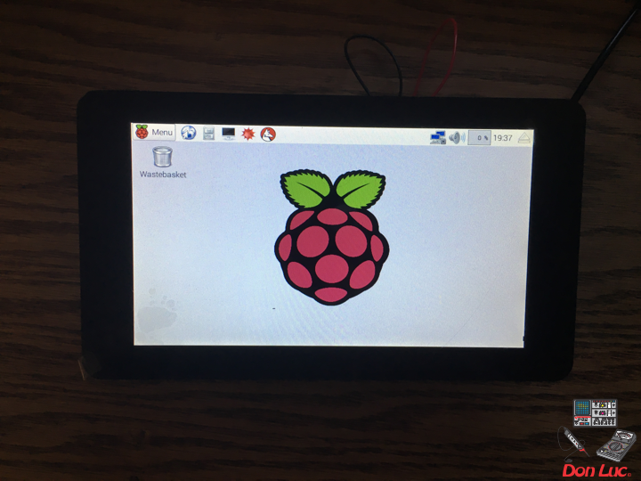
The 7” Touchscreen Monitor for Raspberry Pi gives users the ability to create all-in-one, integrated projects such as tablets, infotainment systems and embedded projects. The 800 x 480 display connects via an adapter board which handles power and signal conversion. Only two connections to the Pi are required; power from the Pi’s GPIO port and a ribbon cable that connects to the DSI port present on all Raspberry Pi’s. Touchscreen drivers with support for 10-finger touch and an on-screen keyboard will be integrated into the latest Raspbian OS for full functionality without the need for a physical keyboard or mouse.
Technical Specification:
* 7” Touchscreen Display
* Screen Dimensions: 194mm x 110mm x 20mm (including standoffs)
* Viewable screen size: 155mm x 86mm
* Screen Resolution 800 x 480 pixels
* 10 finger capacitive touch
* Connects to the Raspberry Pi board using a ribbon cable connected to the DSI port
* Adapter board is used to power the display and convert the parallel signals from the display to the serial (DSI) port on the Raspberry Pi
* Will require the latest version of Raspbian OS to operate correctly
Features and Benefits:
* Turn your Raspberry Pi into a touch screen tablet, infotainment system, or standalone device.
* Truly Interactive – the latest software drivers will support a virtual ‘on screen’ keyboard, so there is no need to plug in a keyboard and mouse.
* Make your own ‘Internet of Things’ (IoT) devices including a visual display. Simply connect your Raspberry Pi, develop a Python script to interact with the display, and you’re ready to create your own home automation devices with touch screen capability.
* A range of educational software and programs available on the Raspberry Pi will be touch enabled, making learning and programming easier on the Raspberry Pi.
Kit Contents:
* 7” Touchscreen Display
* Adapter Board
* DSI Ribbon cable
* 4 x stand-offs and screws (used to mount the adapter board and Raspberry Pi board to the back of the display
* 4 x jumper wires (used to connect the power from the Adapter Board and the GPIO pins on the Pi so the 2Amp power is shared across both units)
Don Luc
Project #7: RGB LCD Shield – Mk01
RGB LCD Shield
Project #7 – Mk01
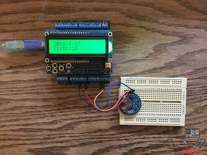
ChronoDot
1 x RGB LCD Shield 16×2 Character Display
1 x Arduino Uno – R3
1 x ProtoScrewShield
1 x ChronoDot
4 x Jumper Wires 3″ M/M
1 x Half-Size Breadboard
A5
A4
GND
3.3V
DonLuc1804Mk07a.ino
// ***** Don Luc *****
// Software Version Information
// 1.03
// DonLuc1804Mk07 1.03
// RGB LCD Shield
// ChronoDot

// include the library code:
#include <Wire.h>
#include <Adafruit_MCP23017.h>
#include <Adafruit_RGBLCDShield.h>
#include <RTClib.h>
#include <RTC_DS3231.h>

RTC_DS3231 RTC;

#define SQW_FREQ DS3231_SQW_FREQ_1024     //0b00001000   1024Hz

Adafruit_RGBLCDShield RGBLCDShield = Adafruit_RGBLCDShield();

#define GREEN 0x2

// ChronoDot
char datastr[100];

void loop() {

  RGBLCDShield.clear();

  timeChrono();

  delay(2000);

}
ChronoDot.ino
void setupChrono() {

  RTC.begin();

  DateTime now = RTC.now();
  DateTime compiled = DateTime(__DATE__, __TIME__);
  RTC.getControlRegisterData( datastr[0] );

}

void timeChrono() {

    DateTime now = RTC.now();
    DateTime isNow (now.unixtime() + 6677 * 86400L + 42500);

    // set the cursor to column 0, line 0
    RGBLCDShield.setCursor(0,0);
    RGBLCDShield.print(isNow.year(), DEC);
    RGBLCDShield.print('/');
    RGBLCDShield.print(isNow.month(), DEC);
    RGBLCDShield.print('/');
    RGBLCDShield.print(isNow.day(), DEC);
    RGBLCDShield.print(' ');
    RGBLCDShield.print(' ');

    // set the cursor to column 0, line 1
    RGBLCDShield.setCursor(0, 1);
    RGBLCDShield.print(isNow.hour(), DEC);
    RGBLCDShield.print(':');
    RGBLCDShield.print(isNow.minute(), DEC);
    RGBLCDShield.print(':');
    RGBLCDShield.print(isNow.second(), DEC);
    RGBLCDShield.print(' ');
    RGBLCDShield.print(' ');

}
setup.ino
void setup() {

  // set up the LCD's number of columns and rows:
  RGBLCDShield.begin(16, 2);

  RGBLCDShield.print("Don Luc");
  RGBLCDShield.setBacklight(GREEN);
   // set the cursor to column 0, line 1
  RGBLCDShield.setCursor(0, 1);
  // print the number of seconds since reset:
  RGBLCDShield.print("ChronoDot");

  delay(5000);

  // ChronoDot
  setupChrono();

  delay(1500); //wait for the sensor to be ready

}
Don Luc
Project #6: MicroView – Mk04
MicroView
Project #6 – Mk04
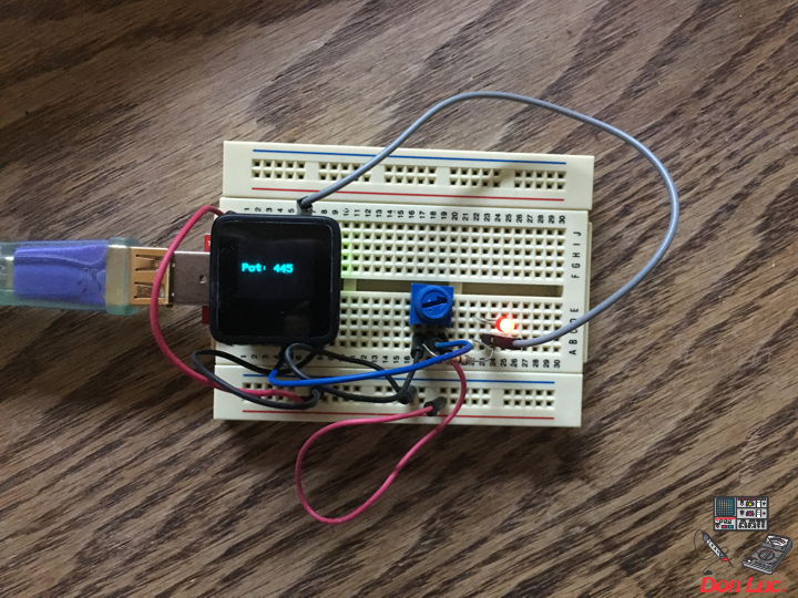
Trimpot – LED
1 x MicroView
1 x MicroView – USB Programmer
1 X Trimpot 10K with Knob
1 X Resistor 2.55k Ohm
1 X 3MM Low Current Red LED
6 x Jumper Wires 3″ M/M
1 x Half-Size Breadboard
05 pin – A2
08 pin – GND
11 pin – 2
15 pin – +5V
DonLuc1804Mk06d.ino
// ***** Don Luc *****
// Software Version Information
// 3.01
// DonLuc1804Mk06 4.04
// MicroView
// Trimpot - LED

// include the library code:
#include <MicroView.h>

// Potentiometer
int potPin = A2;    // select the input pin for the potentiometer
int ledPin = 2;   // select the pin for the LED
int potPot = 0;
String cap = "";

void loop() {

  // Potentiometer
  isCap();

  delay(500);
  uView.clear(PAGE);

}
getPot.ino
void isCap(){

    potPot = analogRead(potPin);    // read the value from the sensor
    cap = "Pot: ";
    cap.concat(potPot);

    uView.setFontType(0);
    uView.setCursor(0,20);
    uView.print( cap );
    uView.display();

}
setup.ino
void setup() {

  uView.begin();       // begin of MicroView
  uView.clear(ALL);    // erase hardware memory inside the OLED controller
  uView.display();     // display the content in the buffer memory, by default it is the MicroView logo
  delay(1000);
  uView.clear(PAGE);   // erase the memory buffer, when next uView.display() is called, the OLED will be cleared.

  uView.setFontType(1);
  uView.setCursor(0,20);
  uView.print("Don Luc");
  uView.display();
  delay(5000);

  uView.clear(PAGE);   // erase the memory buffer, when next uView.display() is called, the OLED will be cleared.

  uView.setFontType(0);
  uView.setCursor(0,20);
  uView.print("TrimpotLED");
  uView.display();
  delay(5000);

  uView.clear(PAGE);

  // ledPin
  pinMode(ledPin, OUTPUT);
  digitalWrite(ledPin, HIGH);  // turn the ledPin on

}
Don Luc