Digital Electronics
Digital Electronics
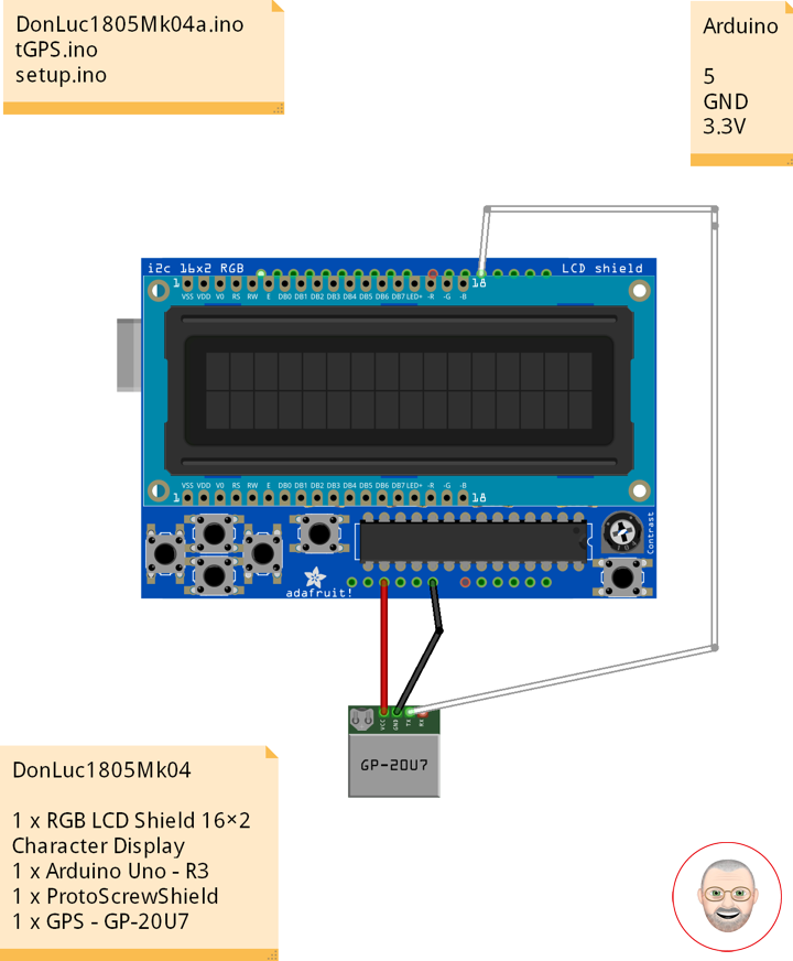
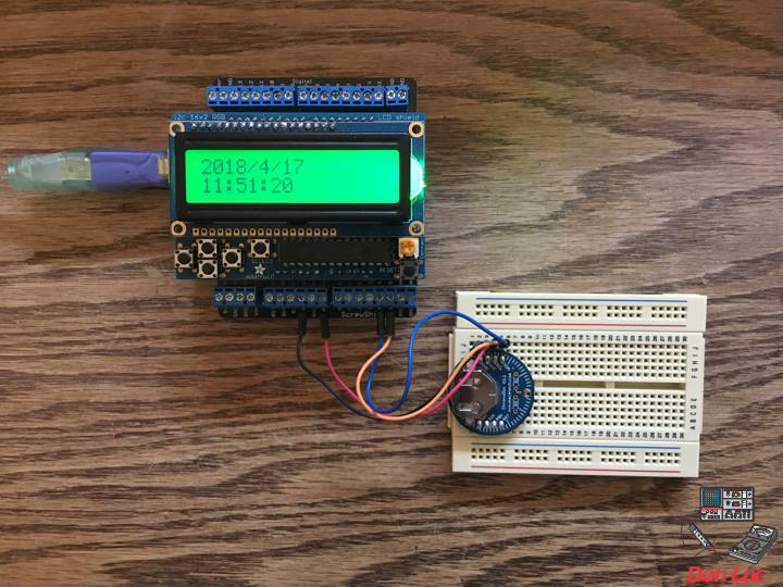
Project #7: RGB LCD Shield – GPS Receiver – Mk02
GPS Receiver
Global Positioning System
The Global Positioning System (GPS), originally Navstar GPS, is a satellite-based radionavigation system owned by the United States government and operated by the United States Air Force. It is a global navigation satellite system that provides geolocation and time information to a GPS receiver anywhere on or near the Earth where there is an unobstructed line of sight to four or more GPS satellites. Obstacles such as mountains and buildings block the relatively weak GPS signals.
The GPS does not require the user to transmit any data, and it operates independently of any telephonic or internet reception, though these technologies can enhance the usefulness of the GPS positioning information. The GPS provides critical positioning capabilities to military, civil, and commercial users around the world. The United States government created the system, maintains it, and makes it freely accessible to anyone with a GPS receiver.
DonLuc1805Mk04
1 x RGB LCD Shield 16×2 Character Display
1 x Arduino UNO – R3
1 x ProtoScrewShield
1 x GPS – GP-20U7
Arduino UNO
Digital 5
GND
3.3V
DonLuc1805Mk04a.ino
// ***** Don Luc *****
// Software Version Information
// 5-4.01
// DonLuc1805Mk04 5-4.01
// RGB LCD Shield
// GPS
// include the library code:
#include <Adafruit_MCP23017.h>
#include <Adafruit_RGBLCDShield.h>
#include <TinyGPS.h>
#include <SoftwareSerial.h>
Adafruit_RGBLCDShield RGBLCDShield = Adafruit_RGBLCDShield();
#define GREEN 0x2
// GPS
#define gpsRXPIN 5
#define gpsTXPIN 4 //this one is unused and doesnt have a conection
SoftwareSerial tGPS(gpsRXPIN, gpsTXPIN);
TinyGPS gps;
// Global variables and functions are declared here, this allows them to be called anywhere
// within the code and is helpful for passing data out of functions. Dont get in the habit \
// of using these though because as your code gets longer its easy to lose track of where
// you are changing these variables and can lead to a headach when a problem arises.
float TargetLat;
float TargetLon;
int Status = 0;
// Function headers can be placed here so that functions can be placed below your setup
// and loop function for a more logical flow of information.
void getGPS( float* lat, float* lon, int* Status);
void loop() {
RGBLCDShield.clear();
// Receives NEMA data from GPS receiver and Parses Latitude and longitude data
// returns information using pointers including info on stagnant data
// Here we tell it to listen to the tGPS serial object
// then call the function that will recieve and parse the signal from the GPS reciver
tGPS.listen();
getGPS(&TargetLat, &TargetLon, &Status);
// Print status to console to know if you are getting good data or not.
// No Lock = 0, Old Data(>5 sec old) = 1, Good Data = 2
// set the cursor to column 0, line 0
RGBLCDShield.setCursor(0,0);
RGBLCDShield.print( "Status:" );
RGBLCDShield.print( Status );
delay(2000);
RGBLCDShield.clear();
// set the cursor to column 0, line 0
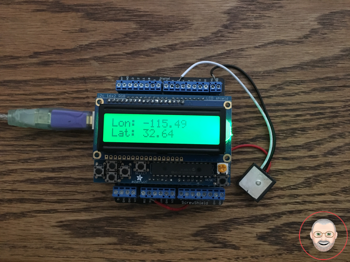
RGBLCDShield.setCursor(0,0);
RGBLCDShield.print( "Lon: " );
RGBLCDShield.print( TargetLon );
// set the cursor to column 0, line 1
RGBLCDShield.setCursor(0, 1);
RGBLCDShield.print( "Lat: " );
RGBLCDShield.print( TargetLat );
delay(5000);
}
tGPS.ino
/* GPS Vector Pointer Target
   This sketch simiulates any system that has a GPS beacon and has the ability to
   broadcast this information for other systems to pick up. This could be a plane/drone
   a car/rover or even a solar panel on a space elevator climber. This recieves updating GPS
   coordinates and from an attached GPS receiver, parses the incoming NEMA data and
   send that information using an Xbee connection to the base station.
*/

void getGPS( float* lat, float* lon, int* Status)
/* This function switches the softserial pin to the one used for GPS then recieves NEMA data from a GPS
   receiver which is passed into a TinyGPS Object and parsed using its internal functions for $GPRMC info. This function uses
   pointers to pass infomation to pass back to parent function which includes Latitude, longitude,( velocity,
   heading) and the status of the GPS signal. Function call where variables can be nammed whatever they want as long as they have &:
   getGPS(&latitude, &longitude, &Status);
*/
{
  // Initilize pin to receive NEMA (have to do it here because we need to switch between
  // software serial pins (if time permits interrupts could be used)

  // define local variables
  float flat;
  float flon;
  unsigned long fix_age;

  //look for serial data from GPS and loop untill the end of NEMA string
  while (tGPS.available())
  {

    int c = tGPS.read();

    if (gps.encode(c));
    {}

  }

  //Pulled parsed data from gps object
  gps.f_get_position(&flat, &flon, &fix_age);
  *lat = flat;
  *lon = flon;

  // check if data is relavent
  if (fix_age == TinyGPS::GPS_INVALID_AGE)
    //No fix detected;
  {
    *Status = 0;
  }

  else if (fix_age > 5000)
    //Warning: possible stale data!;
  {
    *Status = 1;
  }

  else
    //Data is current;
  {
    *Status = 2;
  }

}
setup.ino
void setup() {

  // set up the LCD's number of columns and rows:
  RGBLCDShield.begin(16, 2);

  RGBLCDShield.print("Don Luc");
  RGBLCDShield.setBacklight(GREEN);
   // set the cursor to column 0, line 1
  RGBLCDShield.setCursor(0, 1);
  // print the number of seconds since reset:
  RGBLCDShield.print("GPS - GP-20U7");

  delay(5000);

  // This function is run before the your program begins to loop, here we define the status
  // of pins that are used for inputs and outputs
  pinMode(gpsRXPIN, INPUT);

  // Next communication begins between the three systems along for the baud rate for each
  // some of these can handle a larger baud rate but you need to make sure they match what
  // they are communicating with
  tGPS.begin(9600);
  Serial.begin(9600);

}
Don Luc
Project #6: MicroView – Mk05
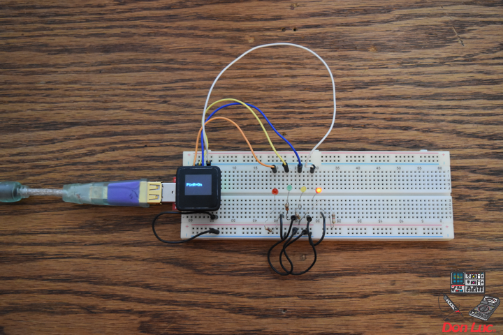
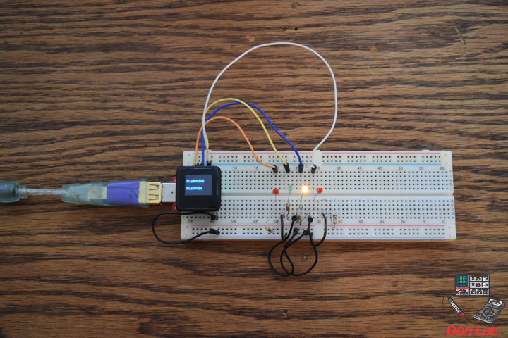

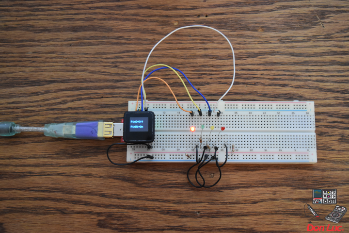
MicroView
Project #6 – Mk05
4 x LED
1 x MicroView
1 x MicroView – USB Programmer
1 X Resistor 620 Ohm
1 X Resistor 5 Ohm
1 X Resistor 250 Ohm
1 X Resistor 200 Ohm
1 X 3mm Low Current Red LED – WP710A10LSRD
1 x 3mm Low Current Yellow LED – WP710A10LYD
1 x 3mm Low Current Green LED – WP710A10LGD
1 x 3mm Low Current Red LED – WP710A10LID
9 x Jumper Wires 3″ M/M
1 x Half-Size Breadboard
08 pin – GND
14 pin – 6
13 pin – 5
12 pin – 3
11 pin – 2
DonLuc1804Mk09a.ino
// ***** Don Luc *****
// Software Version Information
// 5.01
// DonLuc1804Mk06 5.01
// MicroView
// 4 x LED

// include the library code:
#include <MicroView.h>

// 4 x LED
int ledPinR = 2;   // select the pin for the LED Red - WP710A10LSRD
int ledPinY = 3;   // select the pin for the LED Yellow - WP710A10LYD
int ledPinG = 5;   // select the pin for the LED Green - WP710A10LGD
int ledPinR1 = 6;   // select the pin for the LED Red - WP710A10LID

void loop() {

  // 4 x LED
  isLED();

  uView.clear(PAGE);

}
getLED.ino
void isLED(){
digitalWrite(ledPinR, HIGH); // turn the ledPinR on
digitalWrite(ledPinY, HIGH); // turn the ledPinY on
digitalWrite(ledPinG, HIGH); // turn the ledPinG on
digitalWrite(ledPinR1, HIGH); // turn the ledPinR1 on
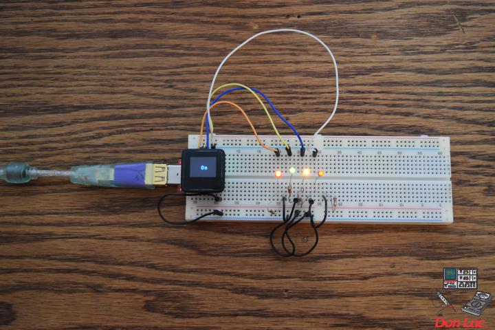
uView.setFontType(1); // set font type 1: Numbers and letters. 7 characters per line (3 lines)
uView.setCursor(0,20);
uView.print( " On" );
uView.display();
delay(5000);
uView.clear(PAGE);
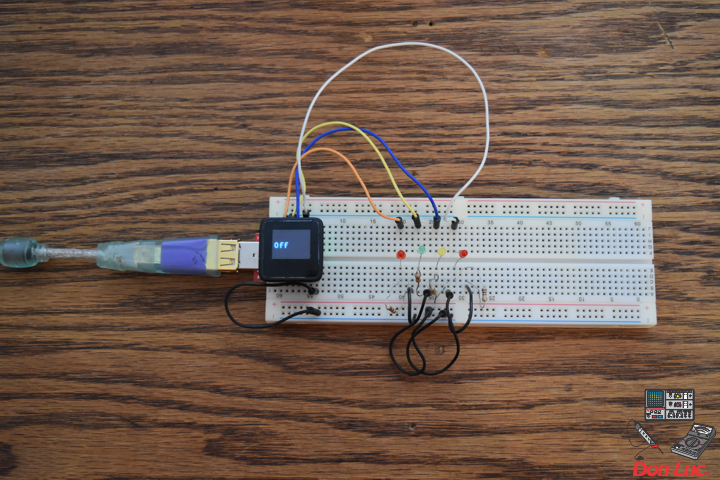
digitalWrite(ledPinR, LOW); // turn the ledPinR off
digitalWrite(ledPinY, LOW); // turn the ledPinY off
digitalWrite(ledPinG, LOW); // turn the ledPinG off
digitalWrite(ledPinR1, LOW); // turn the ledPinR1 off
uView.setCursor(0,20);
uView.print( " Off" );
uView.display();
delay(5000);
uView.clear(PAGE);
digitalWrite(ledPinR, HIGH); // turn the ledPinR on
uView.setFontType(0); // set font type 0: Numbers and letters. 10 characters per line (6 lines)
uView.setCursor(0,20);
uView.print( "PinR=On" );
uView.display();
delay(3000);
uView.clear(PAGE);
digitalWrite(ledPinR, LOW); // turn the ledPinR off
digitalWrite(ledPinY, HIGH); // turn the ledPinY on
uView.setCursor(0,10);
uView.print( "PinR=Off" );
uView.display();
uView.setCursor(0,30);
uView.print( "PinY=On" );
uView.display();
delay(3000);
uView.clear(PAGE);
digitalWrite(ledPinY, LOW); // turn the ledPinY off
digitalWrite(ledPinG, HIGH); // turn the ledPinG on
uView.setCursor(0,10);
uView.print( "PinY=Off" );
uView.display();
uView.setCursor(0,30);
uView.print( "PinG=On" );
uView.display();
delay(3000);
uView.clear(PAGE);
digitalWrite(ledPinG, LOW); // turn the ledPinG off
digitalWrite(ledPinR1, HIGH); // turn the ledPinR1 on
uView.setCursor(0,10);
uView.print( "PinG=Off" );
uView.display();
uView.setCursor(0,30);
uView.print( "PinR1=On" );
uView.display();
delay(3000);
uView.clear(PAGE);
digitalWrite(ledPinR, LOW); // turn the ledPinR off
digitalWrite(ledPinY, LOW); // turn the ledPinY off
digitalWrite(ledPinG, LOW); // turn the ledPinG off
digitalWrite(ledPinR1, LOW); // turn the ledPinR1 off
uView.setFontType(1); // set font type 1: Numbers and letters. 7 characters per line (3 lines)
uView.setCursor(0,20);
uView.print( "Off" );
uView.display();
delay(3000);
uView.clear(PAGE);
}
setup.ino
void setup() {

  uView.begin();       // begin of MicroView
  uView.clear(ALL);    // erase hardware memory inside the OLED controller
  uView.display();     // display the content in the buffer memory, by default it is the MicroView logo
  delay(1000);
  uView.clear(PAGE);   // erase the memory buffer, when next uView.display() is called, the OLED will be cleared.

  uView.setFontType(1); // set font type 1: Numbers and letters. 7 characters per line (3 lines)
  uView.setCursor(0,20);
  uView.print("Don Luc");
  uView.display();
  delay(5000);

  uView.clear(PAGE);     // erase the memory buffer, when next uView.display() is called, the OLED will be cleared.

  uView.setFontType(1);  // set font type 1: Numbers and letters. 7 characters per line (3 lines)
  uView.setCursor(0,20);
  uView.print("4 x LED");
  uView.display();
  delay(5000);

  uView.clear(PAGE);

  // ledPinR, ledPinY, ledPinG, ledPinR1
  pinMode(ledPinR, OUTPUT);
  pinMode(ledPinY, OUTPUT);
  pinMode(ledPinG, OUTPUT);
  pinMode(ledPinR1, OUTPUT);

}
Don Luc
Raspberry Pi 7” Touchscreen Display
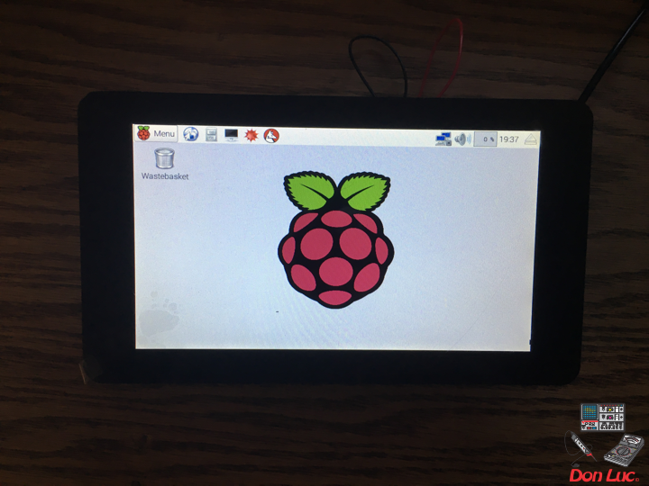
The 7” Touchscreen Monitor for Raspberry Pi gives users the ability to create all-in-one, integrated projects such as tablets, infotainment systems and embedded projects. The 800 x 480 display connects via an adapter board which handles power and signal conversion. Only two connections to the Pi are required; power from the Pi’s GPIO port and a ribbon cable that connects to the DSI port present on all Raspberry Pi’s. Touchscreen drivers with support for 10-finger touch and an on-screen keyboard will be integrated into the latest Raspbian OS for full functionality without the need for a physical keyboard or mouse.
Technical Specification:
* 7” Touchscreen Display
* Screen Dimensions: 194mm x 110mm x 20mm (including standoffs)
* Viewable screen size: 155mm x 86mm
* Screen Resolution 800 x 480 pixels
* 10 finger capacitive touch
* Connects to the Raspberry Pi board using a ribbon cable connected to the DSI port
* Adapter board is used to power the display and convert the parallel signals from the display to the serial (DSI) port on the Raspberry Pi
* Will require the latest version of Raspbian OS to operate correctly
Features and Benefits:
* Turn your Raspberry Pi into a touch screen tablet, infotainment system, or standalone device.
* Truly Interactive – the latest software drivers will support a virtual ‘on screen’ keyboard, so there is no need to plug in a keyboard and mouse.
* Make your own ‘Internet of Things’ (IoT) devices including a visual display. Simply connect your Raspberry Pi, develop a Python script to interact with the display, and you’re ready to create your own home automation devices with touch screen capability.
* A range of educational software and programs available on the Raspberry Pi will be touch enabled, making learning and programming easier on the Raspberry Pi.
Kit Contents:
* 7” Touchscreen Display
* Adapter Board
* DSI Ribbon cable
* 4 x stand-offs and screws (used to mount the adapter board and Raspberry Pi board to the back of the display
* 4 x jumper wires (used to connect the power from the Adapter Board and the GPIO pins on the Pi so the 2Amp power is shared across both units)
Don Luc
Project #7: RGB LCD Shield – Mk01
RGB LCD Shield
Project #7 – Mk01
ChronoDot
1 x RGB LCD Shield 16×2 Character Display
1 x Arduino Uno – R3
1 x ProtoScrewShield
1 x ChronoDot
4 x Jumper Wires 3″ M/M
1 x Half-Size Breadboard
A5
A4
GND
3.3V
DonLuc1804Mk07a.ino
// ***** Don Luc *****
// Software Version Information
// 1.03
// DonLuc1804Mk07 1.03
// RGB LCD Shield
// ChronoDot

// include the library code:
#include <Wire.h>
#include <Adafruit_MCP23017.h>
#include <Adafruit_RGBLCDShield.h>
#include <RTClib.h>
#include <RTC_DS3231.h>

RTC_DS3231 RTC;

#define SQW_FREQ DS3231_SQW_FREQ_1024     //0b00001000   1024Hz

Adafruit_RGBLCDShield RGBLCDShield = Adafruit_RGBLCDShield();

#define GREEN 0x2

// ChronoDot
char datastr[100];

void loop() {

  RGBLCDShield.clear();

  timeChrono();

  delay(2000);

}
ChronoDot.ino
void setupChrono() {

  RTC.begin();

  DateTime now = RTC.now();
  DateTime compiled = DateTime(__DATE__, __TIME__);
  RTC.getControlRegisterData( datastr[0] );

}

void timeChrono() {

    DateTime now = RTC.now();
    DateTime isNow (now.unixtime() + 6677 * 86400L + 42500);

    // set the cursor to column 0, line 0
    RGBLCDShield.setCursor(0,0);
    RGBLCDShield.print(isNow.year(), DEC);
    RGBLCDShield.print('/');
    RGBLCDShield.print(isNow.month(), DEC);
    RGBLCDShield.print('/');
    RGBLCDShield.print(isNow.day(), DEC);
    RGBLCDShield.print(' ');
    RGBLCDShield.print(' ');

    // set the cursor to column 0, line 1
    RGBLCDShield.setCursor(0, 1);
    RGBLCDShield.print(isNow.hour(), DEC);
    RGBLCDShield.print(':');
    RGBLCDShield.print(isNow.minute(), DEC);
    RGBLCDShield.print(':');
    RGBLCDShield.print(isNow.second(), DEC);
    RGBLCDShield.print(' ');
    RGBLCDShield.print(' ');

}
setup.ino
void setup() {

  // set up the LCD's number of columns and rows:
  RGBLCDShield.begin(16, 2);

  RGBLCDShield.print("Don Luc");
  RGBLCDShield.setBacklight(GREEN);
   // set the cursor to column 0, line 1
  RGBLCDShield.setCursor(0, 1);
  // print the number of seconds since reset:
  RGBLCDShield.print("ChronoDot");

  delay(5000);

  // ChronoDot
  setupChrono();

  delay(1500); //wait for the sensor to be ready

}
Don Luc
Project #6: MicroView – Mk04
MicroView
Project #6 – Mk04
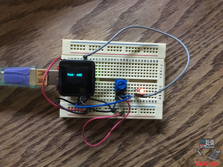
Trimpot – LED
1 x MicroView
1 x MicroView – USB Programmer
1 X Trimpot 10K with Knob
1 X Resistor 2.55k Ohm
1 X 3MM Low Current Red LED
6 x Jumper Wires 3″ M/M
1 x Half-Size Breadboard
05 pin – A2
08 pin – GND
11 pin – 2
15 pin – +5V
DonLuc1804Mk06d.ino
// ***** Don Luc *****
// Software Version Information
// 3.01
// DonLuc1804Mk06 4.04
// MicroView
// Trimpot - LED

// include the library code:
#include <MicroView.h>

// Potentiometer
int potPin = A2;    // select the input pin for the potentiometer
int ledPin = 2;   // select the pin for the LED
int potPot = 0;
String cap = "";

void loop() {

  // Potentiometer
  isCap();

  delay(500);
  uView.clear(PAGE);

}
getPot.ino
void isCap(){

    potPot = analogRead(potPin);    // read the value from the sensor
    cap = "Pot: ";
    cap.concat(potPot);

    uView.setFontType(0);
    uView.setCursor(0,20);
    uView.print( cap );
    uView.display();

}
setup.ino
void setup() {

  uView.begin();       // begin of MicroView
  uView.clear(ALL);    // erase hardware memory inside the OLED controller
  uView.display();     // display the content in the buffer memory, by default it is the MicroView logo
  delay(1000);
  uView.clear(PAGE);   // erase the memory buffer, when next uView.display() is called, the OLED will be cleared.

  uView.setFontType(1);
  uView.setCursor(0,20);
  uView.print("Don Luc");
  uView.display();
  delay(5000);

  uView.clear(PAGE);   // erase the memory buffer, when next uView.display() is called, the OLED will be cleared.

  uView.setFontType(0);
  uView.setCursor(0,20);
  uView.print("TrimpotLED");
  uView.display();
  delay(5000);

  uView.clear(PAGE);

  // ledPin
  pinMode(ledPin, OUTPUT);
  digitalWrite(ledPin, HIGH);  // turn the ledPin on

}
Don Luc
Project #6: MicroView – Mk03
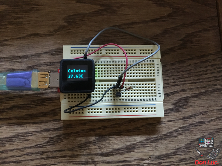
MicroView
Project #6 – Mk03
1 x MicroView
1 x DS18S20
1 x Resistor 1.65k Ohm
3 x Jumper Wires 3″ M/M
08 pin – GND
11 pim – 2
15 pin – +5V
DonLuc1804Mk05b.ino
// ***** Don Luc *****
// Software Version Information
// 3.01
// DonLuc1804Mk05 3.01
// MicroView
// OneWire
// DS18S20

#include <MicroView.h>
#include <OneWire.h>
// Temperature chip i/o
int DS18S20_Pin = 2; //DS18S20 Signal pin on digital 2
OneWire ds(DS18S20_Pin);  // on digital pin 2
float temperature = 0;
String tempZ = "";

void loop() {

  // Temperature chip i/o
  temperatu();
  isTe();

	uView.setFontType(1);
	uView.setCursor(0,20);
	uView.print("Don Luc");
	uView.display();
	delay(1000);

	uView.clear(PAGE);

}
getTemperature.ino
float getTemp() {

  //returns the temperature from one DS18S20 in DEG Celsius
  byte data[12];
  byte addr[8];

  if ( !ds.search(addr)) {
      //no more sensors on chain, reset search
      ds.reset_search();
      return -1001;
  }

  if ( OneWire::crc8( addr, 7) != addr[7]) {
      return -1002;
  }

  if ( addr[0] != 0x10 && addr[0] != 0x28) {
      return -1003;
  }

  ds.reset();
  ds.select(addr);
  ds.write(0x44,1); // start conversion, with parasite power on at the end

  byte present = ds.reset();
  ds.select(addr);
  ds.write(0xBE); // Read Scratchpad


  for (int i = 0; i < 9; i++) { // we need 9 bytes
    data[i] = ds.read();
  }

  ds.reset_search();

  byte MSB = data[1];
  byte LSB = data[0];

  float tempRead = ((MSB << 8) | LSB); //using two's compliment
  float TemperatureSum = tempRead / 16;

  return TemperatureSum;

}

void temperatu(){

  temperature = getTemp();

}

void isTe() {

  tempZ = "";
  uView.setFontType(1);
  uView.setCursor(0,10);
  uView.print("Celsius");
  uView.setCursor(0,30);
  tempZ.concat(temperature);
  tempZ.concat("C");
  uView.print( tempZ );
  uView.display();
  delay(5000);

  uView.clear(PAGE);

}
setup.ino
void setup() {

  uView.begin();       // begin of MicroView
  uView.clear(ALL);    // erase hardware memory inside the OLED controller
  uView.display();     // display the content in the buffer memory, by default it is the MicroView logo
  delay(1000);
  uView.clear(PAGE);   // erase the memory buffer, when next uView.display() is called, the OLED will be cleared.

  uView.setFontType(1);
  uView.setCursor(0,20);
  uView.print("Don Luc");
  uView.display();
  delay(5000);

  uView.clear(PAGE);   // erase the memory buffer, when next uView.display() is called, the OLED will be cleared.

  uView.setFontType(1);
  uView.setCursor(0,20);
  uView.print("OneWire");
  uView.display();
  delay(5000);

  uView.clear(PAGE);

  uView.setFontType(1);
  uView.setCursor(0,20);
  uView.print("DS18S20");
  uView.display();
  delay(5000);

  uView.clear(PAGE);

}
Don Luc
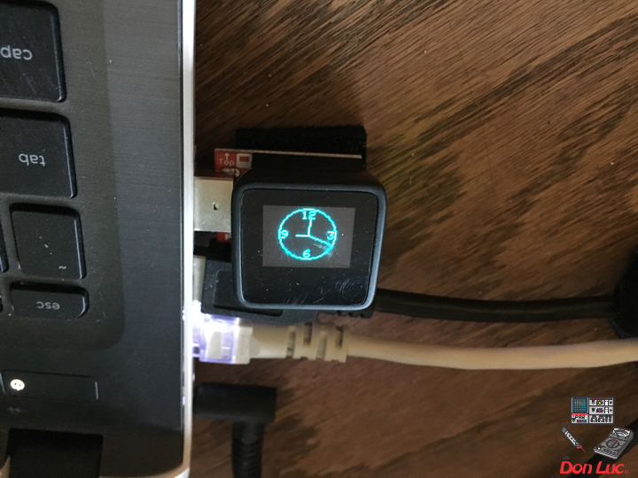
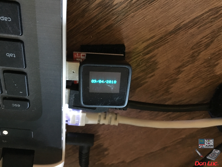
Project #6: MicroView – Mk02
DonLuc1804Mk04a.ino
// ***** Don Luc *****
// Software Version Information
// 2.01
// DonLuc1804Mk04 2.01
// MicroView

#include <MicroView.h>
#include <Time.h>
#include <TimeLib.h>
// This is the radius of the clock:
#define CLOCK_SIZE 23
// Use these defines to set the clock's begin time
#define HOUR 9
#define MINUTE 00
#define SECOND 00
#define DAY 9
#define MONTH 4
#define YEAR 2018
// LCD W/H
const uint8_t maxW = uView.getLCDWidth();
const uint8_t midW = maxW/2;
const uint8_t maxH = uView.getLCDHeight();
const uint8_t midH = maxH/2;
// Clock
long zzz = 0;
static boolean firstDraw = false;
static unsigned long mSec = millis() + 1000;
static float degresshour, degressmin, degresssec, hourx, houry, minx, miny, secx, secy;

void loop() {

  drawFace();

  zzz = 0;
  while(zzz < 5000)
  {

     drawTime();
     zzz++;

  }

  uView.clear(PAGE);

  firstDraw = false;

  uView.setFontType(0);
  uView.setCursor(0,20);
  uView.print("09/04/2018");
  uView.display();
  delay(5000);

  uView.clear(PAGE);

}
drawFace.ino
void drawFace()
{

  // Draw the clock face. That includes the circle outline and
  // the 12, 3, 6, and 9 text.
  uView.setFontType(0); // set font type 0 (Smallest)

  uint8_t fontW = uView.getFontWidth();
  uint8_t fontH = uView.getFontHeight();

  //uView.setCursor(27, 0); // points cursor to x=27 y=0
  uView.setCursor(midW-fontW-1, midH-CLOCK_SIZE+1);
  uView.print(12);  // Print the "12"
  uView.setCursor(midW-(fontW/2)-1, midH+CLOCK_SIZE-fontH-1);
  uView.print(6);  // Print the "6"
  uView.setCursor(midW-CLOCK_SIZE+1, midH-fontH/2);
  uView.print(9);  // Print the "9"
  uView.setCursor(midW+CLOCK_SIZE-fontW-2, midH-fontH/2);
  uView.print(3);  // Print the "3"
  uView.circle(midW-1, midH-1, CLOCK_SIZE);

  //Draw the clock
  uView.display();

}
drawTime.ino
void drawTime()
{

  // If mSec
  if (mSec != (unsigned long)second())
  {
    // First time draw requires extra line to set up XOR's:
    if (firstDraw)
    {
      uView.line(midW, midH, 32 + hourx, 24 + houry, WHITE, XOR);
      uView.line(midW, midH, 32 + minx, 24 + miny, WHITE, XOR);
      uView.line(midW, midH, 32 + secx, 24 + secy, WHITE, XOR);
    }
    // Calculate hour hand degrees:
    degresshour = (((hour() * 360) / 12) + 270) * (PI / 180);
    // Calculate minute hand degrees:
    degressmin = (((minute() * 360) / 60) + 270) * (PI / 180);
    // Calculate second hand degrees:
    degresssec = (((second() * 360) / 60) + 270) * (PI / 180);

    // Calculate x,y coordinates of hour hand:
    hourx = cos(degresshour) * (CLOCK_SIZE / 2.5);
    houry = sin(degresshour) * (CLOCK_SIZE / 2.5);
    // Calculate x,y coordinates of minute hand:
    minx = cos(degressmin) * (CLOCK_SIZE / 1.4);
    miny = sin(degressmin) * (CLOCK_SIZE / 1.4);
    // Calculate x,y coordinates of second hand:
    secx = cos(degresssec) * (CLOCK_SIZE / 1.1);
    secy = sin(degresssec) * (CLOCK_SIZE / 1.1);

    // Draw hands with the line function:
    uView.line(midW, midH, midW+hourx, midH+houry, WHITE, XOR);
    uView.line(midW, midH, midW+minx, midH+miny, WHITE, XOR);
    uView.line(midW, midH, midW+secx, midH+secy, WHITE, XOR);

    // Set firstDraw flag to true, so we don't do it again.
    firstDraw = true;

    // Actually draw the hands with the display() function.
    uView.display();

  }

}
setup.ino
void setup() {

  // Set the time in the time library:
  setTime(HOUR, MINUTE, SECOND, DAY, MONTH, YEAR);

  uView.begin();       // begin of MicroView
  uView.clear(ALL);    // erase hardware memory inside the OLED controller
  uView.display();     // display the content in the buffer memory, by default it is the MicroView logo
  delay(1000);
  uView.clear(PAGE);   // erase the memory buffer, when next uView.display() is called, the OLED will be cleared.

  uView.setFontType(1);
  uView.setCursor(0,20);
  uView.print("Don Luc");
  uView.display();
  delay(5000);

  uView.clear(PAGE);

  uView.display();  // display the content in the buffer

  // Draw clock face (circle outline & text):
  drawFace();

}
Don Luc
Project #6: MicroView – Mk01
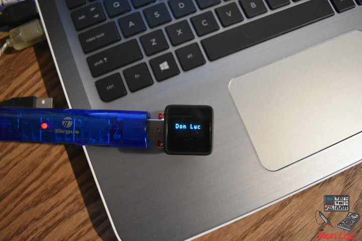
DonLuc1804Mk03b.ino
// ***** Don Luc *****
// Software Version Information
// 1.01
// DonLuc1804Mk03 1.01
// MicroView

#include <MicroView.h>

void loop() {

	uView.setFontType(0);
	uView.setCursor(0,20);
	uView.print("  Don Luc  ");
	uView.display();
	delay(5000);

	uView.clear(PAGE);

	uView.setFontType(1);
	uView.setCursor(0,20);
	uView.print("Don Luc");
	uView.display();
	delay(5000);

	uView.clear(PAGE);

}
setup.ino
void setup() {

  uView.begin();       // begin of MicroView
  uView.clear(ALL);    // erase hardware memory inside the OLED controller
  uView.display();     // display the content in the buffer memory, by default it is the MicroView logo
  delay(1000);
  uView.clear(PAGE);   // erase the memory buffer, when next uView.display() is called, the OLED will be cleared.

}
MicroView
Project #6 – Mk01
Don Luc
Project #5: Lamps – Mk01
DonLuc1804Mk02.ino
// ***** Don Luc *****
// Software Version Information
// 1.01
// DonLuc1804Mk02 1.01
// Lamps

#include <Adafruit_NeoPixel.h>
// Which pin on the Arduino is connected to the NeoPixels
// Pin connected => 6
#define PIN 6
// How many NeoPixels are attached to the Arduino
// NUMPIXELS => 4
#define NUMPIXELS 4
Adafruit_NeoPixel pixels = Adafruit_NeoPixel(NUMPIXELS, PIN, NEO_GRB + NEO_KHZ800);
// Panel Mount 1K potentiometer Bright
// Bright => A0
const int sensorBright = A0;
int sBright = 0;
int brightVal = 0;         // the sensor value
int brightMin = 0;        // minimum sensor value
int brightMax = 0;           // maximum sensor value
// Panel Mount 1K potentiometer
// Delay => A1
const int sensorDelay = A1;
long delayVal = 0;
// Rotary Switch - 10 Position
// Number => A2 (0 => 9)
const int sensorNumber = A2;
// Panel Mount 1K potentiometer
// Red - Led
const int sensorRed = 9;
int red = 0;
int redMin = 0;
int redMax = 0;
// Panel Mount 1K potentiometer
// Green - Led
const int sensorGreen = 8;
int green = 0;
int greenMin = 0;
int greenMax = 0;
// Panel Mount 1K potentiometer
// Blue - Led
const int sensorBlue = 7;
int blue = 0;
int blueMin = 0;
int blueMax = 0;
// variables:
//int x = 0;
int y = 0;
int z = 0;

void loop() {

  number();

}
bright.ino
void bright(){

    switch (sBright) {
        case 1:
            brightVal = 255;
            break;
         default:
            // read the sensor:
            brightVal = analogRead(sensorBright);
            // apply the calibration to the sensor reading
            brightVal = map(brightVal, brightMin, brightMax, 0, 255);
            // in case the sensor value is outside the range seen during calibration
            brightVal = constrain(brightVal, 0, 255);
            break;
    }

}
iled.ino
void iled() {

   // red
   red = analogRead(sensorRed);
   // apply the calibration to the sensor reading red
   red = map(red, redMin, redMax, 0, 255);
   // in case the sensor value is outside the range seen during calibration
   red = constrain(red, 0, 255);
   // green
   green = analogRead(sensorGreen);
   // apply the calibration to the sensor reading red
   green = map(green, greenMin, greenMax, 0, 255);
   // in case the sensor value is outside the range seen during calibration
   green = constrain(green, 0, 255);
   // blue
   blue = analogRead(sensorBlue);
   // apply the calibration to the sensor reading red
   blue = map(blue, blueMin, blueMax, 0, 255);
   // in case the sensor value is outside the range seen during calibration
   blue = constrain(blue, 0, 255);

}
neopix.ino
void neopix() {

  for(int i=0; i<NUMPIXELS; i++){

    // bright
    bright();
    pixels.setBrightness( brightVal );
    // pixels.Color takes RGB values, from 0,0,0 up to 255,255,255
    pixels.setPixelColor(i, pixels.Color(red,green,blue));
    // show
    pixels.show(); // This sends the updated pixel color to the hardware.
    // delay
    delay(50); // Delay for a period of time (in milliseconds).

  }

}
neopixt.ino
void neopixt() {

  for(int i=4; i<NUMPIXELS; i--){

    // bright
    bright();
    pixels.setBrightness( brightVal );
    // pixels.Color takes RGB values, from 0,0,0 up to 255,255,255
    pixels.setPixelColor(i, pixels.Color(red,green,blue));
    // show
    pixels.show(); // This sends the updated pixel color to the hardware.
    // delay
    delay(50); // Delay for a period of time (in milliseconds).

  }

}
number.ino
void number(){

  z = analogRead(sensorNumber);
  y = (z / 127);

  sBright = 20000;

  // range value:
  switch (y) {
    case  0:
      // Led
      iled();
      // neopix
      neopix();
      // delay
      delayVal = (0);
      break;
    case 1:
      // Led
      iled();
      // neopix
      neopix();
      // delay
      sdelay();
      break;
    case 2:
      // Led
      iled();
      // neopixt
      neopixt();
      // delay
      sdelay();
      break;
    case 3:
      // White
      red = 255;
      green = 255;
      blue = 255;
      // neopix
      neopix();
      // delay
      delayVal = (0);
      break;
    case 4:
      // Green
      red = 0;
      green = 255;
      blue = 0;
      // neopix
      neopix();
      // delay
      delayVal = (0);
      break;
    case 5:
      // Red
      red = 255;
      green = 0;
      blue = 0;
      // neopix
      neopix();
      // delay
      delayVal = (0);
      break;
    case 6:
      // White
      red = 255;
      green = 255;
      blue = 255;
      // neopix
      neopix();
      // delay
      sdelay();
      break;
    case 7:
      // Green
      red = 0;
      green = 255;
      blue = 0;
      // neopix
      neopix();
      // delay
      sdelay();
      break;
    case 8:
      // Red
      red = 255;
      green = 0;
      blue = 0;
      // neopix
      neopix();
      // delay
      sdelay();
      break;
    case 9:

      break;
  }

}
sdelay.ino
void sdelay() {

    delayVal = analogRead(sensorDelay);
    delayVal = (250 * delayVal);

}
setup.ino
void setup() {

    pixels.begin(); // This initializes the NeoPixel library.

}
Don Luc
Nixie Clock
“All-In-One” Arduino Nixie Clock
Detailed Description
The Arduino “All-In-One” Nixie Clock kit drives 6 IN-14 Nixie Tubes in a traditional “6 in a row” set up. It’s packed full of features, and at the end of the simple build you will have a beautiful IN-14 Nixie Clock. The board is small (150mm x 50mm), and is an easy to build and is a tried and tested design, with many hundreds of units sold.
This kit is based on an Arduino (Atmel ATMega) micro controller. You don’t need to own an Arduino to use this kit! It is self contained and runs without an external Arduino board.
The controller comes pre-programmed. You you can download, modify and upload the open source code if you wish.
This kit is ideal if you want to make an unusual or eye catching clock in a custom case.
Even better: The code is open source, with regular updates and new features.
WiFi Time Provider
If you already have a Clock with the battery-backed RTC (Real Time Clock) module, you can easily upgrade it to use the WiFi time provider module.
This gives you all the advantages of the WiFi kit. You need to have firmware V44 or later to use this.
You set the WiFi provider once once, and it never needs setting again, ever! It also allows you to configure the clock using a browser.
Don Luc